
관련 제조 공정
Metal 3D printing, also called metal additive manufacturing, builds metal parts from digital 3D model data by adding material rather than cutting it from stock or forming it in a mold. For product engineers and sourcing teams, it is most useful when a project needs prototype validation, low-volume metal parts, complex internal channels, lattice structures, or frequent design iteration before tooling is justified.
The production decision should not be based on whether metal 3D printing is more “advanced.” The practical question is whether its build method, material availability, post-processing route, tolerance capability, surface finish, inspection burden, lead time, and volume economics fit the part. For stable small complex metal parts, 금속 사출 성형(MIM) may become more suitable after the design is fixed and the expected volume supports tooling. This page explains metal 3D printing as a related manufacturing process and routes users who need deeper production comparison to the MIM 대 금속 3D 프린팅 페이지를 참조하십시오.
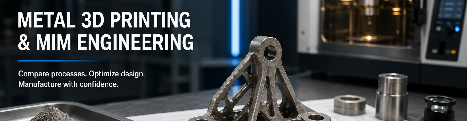
핵심 결론: Metal 3D printing should be reviewed as a manufacturing route with downstream controls, not simply as a direct way to print any metal part.
Metal 3D printing is strongest when a part benefits from low tooling dependency, complex internal geometry, rapid design changes, or low-volume validation. It becomes less attractive when the geometry is stable, the part is small and repeatable, critical surfaces need tight finishing, and volume can support tooling-based production such as MIM.
What Is Metal 3D Printing?
Definition: Metal 3D printing is a metal additive manufacturing route that creates metal parts from digital 3D model data by adding material in controlled layers or deposited regions. It is commonly reviewed for prototypes, low-volume parts, internal channels, lattice structures, and metal geometries that are difficult to machine or mold economically.
Metal 3D printing is a group of additive manufacturing processes used to make metal parts directly from digital geometry. Instead of starting from bar stock, sheet metal, casting molds, or injection tooling, the process builds the part layer by layer or deposits material into selected regions according to the digital build plan.
In formal engineering language, this topic belongs under additive manufacturing. ISO/ASTM terminology defines additive manufacturing around the successive addition of material to create three-dimensional physical geometry from model data. In B2B sourcing language, “metal 3D printing” is often the clearer term because it limits the discussion to metal components rather than plastic prototyping, ceramic AM, software, or general 3D printing equipment.
Metal 3D Printing vs Metal Additive Manufacturing
| Term | 실제 의미 | Best Use on This Page |
|---|---|---|
| 금속 3D 프린팅 | Common search and buyer-facing term for printed metal parts. | Main page topic and primary user-facing term. |
| 금속 적층 제조 | More formal engineering and standards-oriented term. | Use naturally when explaining process categories and technical references. |
| 적층 제조 | Broad umbrella term covering metals, polymers, ceramics, composites, and multiple process families. | Mention only as the parent concept to avoid attracting unrelated search intent. |
For this related-process page, the title and main wording should stay focused on Metal 3D Printing. A broader “Additive Manufacturing” page would attract users looking for non-metal AM, DfAM training, machines, software, or general prototyping information, which is not the main purpose of this XTMIM process-selection page.
How It Differs from Subtractive and Formative Processes
Metal 3D printing differs from CNC 가공, MIM, 및 분말 야금 because the geometry is created by adding material according to digital build data. That difference changes the cost model, inspection plan, post-processing route, and production-volume logic.
| 제조 경로 | Basic Logic | Typical Process Question |
|---|---|---|
| CNC 가공 | Remove material from solid stock. | Is the geometry machinable and cost-effective from bar, plate, or billet? |
| MIM | Mold fine metal powder and binder feedstock, then debind and sinter. | Is the small complex part suitable for tooling-based repeat production? |
| PM | Compact metal powder in a die, then sinter. | Is the geometry pressable and cost-sensitive at high volume? |
| 금속 3D 프린팅 | Build metal geometry additively from digital data. | Does the design benefit from low tooling dependency, internal complexity, or rapid iteration? |
Main Metal 3D Printing Processes
Metal 3D printing is not one single process. A common mistake is to treat every printed metal part as if it comes from the same machine and has the same density, surface finish, tolerance behavior, and post-processing requirement. In practice, the process family affects cost, build risk, material behavior, inspection needs, and whether the result is suitable for prototype use only or production consideration.

핵심 결론: Users should not judge all metal 3D printed parts by one process route or one sample result.
| Process Family | What Changes in Engineering Review | Main Confirmation Before RFQ |
|---|---|---|
| Laser Powder Bed Fusion / LPBF | Build orientation, support contact, residual stress, as-built surface roughness, heat treatment, and machining allowance often drive the final result. | Confirm critical surfaces, support removal access, inspection method, and which dimensions require post-machining. |
| Metal Binder Jetting | Green-part handling, binder removal, sintering shrinkage, density, and distortion control become major process risks. | Confirm material route, sintering allowance, density target, dimensional risk, and whether MIM may be a better production route. |
| 바운드 금속 압출 | Extrusion-based shaping may be useful for prototypes, but debinding, sintering, surface finish, and dimensional capability must be reviewed carefully. | Confirm whether the part is only for prototype validation or whether it must meet production-grade mechanical and dimensional requirements. |
| 직접 에너지 증착(DED) | DED is often more relevant to larger parts, repair, build-up, or feature addition than small precision production parts. | Confirm part size, material deposition need, finishing allowance, and whether another process is more suitable for small components. |
Laser Powder Bed Fusion / LPBF / DMLS / SLM
Laser powder bed fusion uses a laser to selectively melt and fuse regions of metal powder layer by layer. It is often considered for complex metal parts, lightweight structures, internal channels, and low-volume production where tooling is difficult to justify.
From a design review perspective, the issue is not only whether the part can be printed. Support contact areas, residual stress, orientation, as-built surface roughness, heat treatment, machining stock, and inspection access can all affect the final part.
Electron Beam Powder Bed Fusion
Electron beam powder bed fusion also belongs to the powder bed fusion family, but it uses an electron beam rather than a laser. It is commonly associated with vacuum processing and selected high-performance metal applications.
For this page, it should remain a brief process-family explanation. Most users comparing MIM with metal 3D printing are more likely to encounter LPBF, DMLS, SLM, binder jetting, or general service-provider terminology than deep electron beam process details.
Metal Binder Jetting
Metal binder jetting prints geometry by selectively applying binder into a metal powder bed. It may involve green-part handling, binder removal, and sintering, so it is sometimes confused with MIM.
The forming method is different. Binder jetting builds geometry layer by layer in a powder bed. MIM injects fine metal powder and binder feedstock into a mold cavity before debinding and sintering. PM compacts metal powder in a die and then sinters the compact. These routes may share powder and sintering language, but their tooling, geometry limits, cost logic, and production controls are different.
For MIM-specific thermal processing, see the MIM 소결 공정 및 MIM 피드스톡 페이지를 방문하십시오.
Directed Energy Deposition and Bound Metal Extrusion
Directed energy deposition uses focused energy to melt material as it is deposited. Depending on the system, the feedstock may be powder or wire. In process-selection terms, DED is often more relevant to larger parts, repair, build-up, or feature addition than to small high-volume precision components.
Bound metal extrusion uses metal-filled material that is shaped through an extrusion-based process and then typically requires debinding and sintering. It can be useful for prototypes, fixtures, and selected low-volume parts, but it should not be treated as equivalent to high-volume MIM production.
How the Metal 3D Printing Workflow Usually Works
Metal 3D printing is often presented as a direct digital process, but functional metal parts rarely end at the printing stage. Post-processing can influence cost, delivery time, dimensional accuracy, mechanical performance, surface acceptance, and inspection planning.

핵심 결론: Printing is only one part of the full metal AM route. Different metal AM processes may require different thermal, debinding, sintering, machining, or inspection steps.
- CAD model and requirement review: The supplier checks geometry, critical dimensions, functional surfaces, target material, and application conditions.
- Build preparation: The part is oriented, sliced, and prepared for printing. Orientation can affect supports, surface quality, strength direction, distortion risk, and post-processing access.
- Printing or forming: The selected process builds the geometry through powder bed fusion, binder jetting, DED, bound metal extrusion, or another metal AM route.
- Powder removal, green-part handling, or support removal: This step depends strongly on the process. Internal channels, blind cavities, thin ribs, and fragile green parts can create handling risk.
- Thermal processing: Some routes require debinding and sintering. Others may require stress relief, heat treatment, or HIP depending on material and application.
- Machining and surface finishing: Critical surfaces, threads, sealing areas, bearing seats, and assembly datums may still require CNC machining or finishing.
- Inspection and acceptance review: Dimensional inspection, surface inspection, material verification, and functional checks may be needed before production approval.
| Workflow Stage | 엔지니어링 리스크 | 검토해야 할 사항 |
|---|---|---|
| CAD review | Features may be printable but not inspectable, cleanable, or finishable. | Critical dimensions, datum strategy, functional surfaces, internal channels, and access for post-processing. |
| Build orientation | Distortion, support marks, anisotropy, and surface variation may appear in different areas of the same part. | Orientation strategy, support access, critical surfaces, and build-direction sensitivity. |
| Printing | Porosity, incomplete fusion, local defects, or variation between builds can affect acceptance. | Process route, material maturity, supplier capability, and inspection plan. |
| Depowdering / support removal | Powder trapping, damaged features, or inaccessible surfaces can affect functional parts. | Internal channels, blind holes, thin walls, lattice structures, and cleaning access. |
| Thermal processing | Dimensional change, distortion, residual stress relief behavior, or sintering-related shrinkage may affect tolerances. | Material route, post-processing sequence, allowance strategy, and acceptance criteria. |
| Machining / finishing | Added cost and datum mismatch can offset the advantage of direct printing. | Which surfaces truly need machining, polishing, coating, or sealing control. |
| 최종 검사 | Quality may not match drawing intent if inspection is planned too late. | Inspection method, functional checks, material verification, and drawing notes. |
When Metal 3D Printing Is a Good Fit
Metal 3D printing is most valuable when the part benefits from digital flexibility, complex geometry, or low tooling dependency. It is not automatically the lowest-cost process, but it can reduce early development risk when the design is not ready for tooling.

핵심 결론: Process selection depends on production stage, annual volume, geometry type, tolerance needs, and tooling logic. Internal channels and lattice structures usually favor metal 3D printing, while small complex repeat-production external features may favor MIM.
| Good-Fit Situation | Why Metal 3D Printing May Work |
|---|---|
| Low-volume prototypes | No dedicated mold is required, so design iteration can be faster before production tooling decisions. |
| Complex internal channels | Internal flow paths, cooling passages, and enclosed features may be difficult or impossible with CNC or MIM tooling. |
| Lattice or lightweight structures | Additive methods can create geometry that is not practical with subtractive machining or mold-based routes. |
| 잦은 설계 변경 | Digital build data can be revised before the process is locked. |
| High-value low-volume components | Higher unit cost may be acceptable when tooling cost and schedule cannot be justified. |
| Early functional testing | Engineers can test approximate geometry, fit, assembly, or packaging before committing to production tooling. |
Composite Field Scenario for Engineering Training: Prototype Success but Production Route Not Confirmed
- 발생한 문제:
- A small metal bracket was successfully prototyped by metal 3D printing. The printed sample fit the assembly, so the buyer assumed the part was ready for high-volume production.
- 발생 원인:
- The prototype confirmed external shape, but it did not confirm production economics, final surface requirements, tooling feasibility, or whether the geometry was suitable for another production route.
- 실제 시스템적 원인:
- The team treated prototype feasibility as production feasibility and did not separate design validation from process validation.
- 수정 방법:
- The drawing was reviewed again based on annual volume, critical dimensions, functional surfaces, and tolerance needs. Some features were simplified for a mold-based route, and secondary machining was limited to critical contact areas.
- 재발 방지 방법:
- Use metal 3D printing prototypes to test geometry, but perform a separate MIM, CNC, PM, or casting suitability review before production planning.
Typical Engineering Review Limits for Metal 3D Printing
Metal 3D printing capability is not universal. Specific tolerances, density, surface finish, mechanical properties, and acceptance criteria should be confirmed by the selected AM process, material route, supplier qualification, post-processing plan, and inspection method.
| 검토 항목 | Typical Question | 중요성 |
|---|---|---|
| Build size | Can the part fit the selected AM machine and build orientation? | Build envelope and orientation can limit part feasibility before cost is even reviewed. |
| 공차 | Which dimensions must be printed as-built, and which dimensions require machining? | As-built dimensions may not meet functional surfaces, datum features, sealing faces, or precision bores. |
| 표면 마감 | Which faces are sealing, sliding, cosmetic, bearing, or assembly-critical? | Printed surfaces often need finishing, polishing, coating, or machining before functional acceptance. |
| Support and orientation | Where will supports contact the part, and can they be removed without damaging critical features? | Support marks, distortion, and build direction can affect final geometry and surface quality. |
| 내부 채널 | Can powder be removed, cleaned, and inspected from internal features? | Hidden trapped powder or inaccessible surfaces can create functional and quality risks. |
| 체적 | Is the project a prototype, pilot run, bridge production, or repeat production part? | Volume changes the cost logic and may shift the preferred process toward MIM, CNC, PM, or casting. |
When Metal 3D Printing Is Usually Not the First Choice
Metal 3D printing is not always the best process for small metal parts, especially when the design is stable and production volume is high enough to support tooling. The main limitations usually relate to unit cost, build time, post-processing, surface finish, inspection burden, and repeatability at scale.
| 상황 | Why Another Process May Be Better |
|---|---|
| High-volume small parts | Printing time and post-processing can become less economical than tooling-based production. |
| 단순한 형상 | CNC, PM, stamping, casting, or die casting may be more cost-effective. |
| Tight cosmetic or sealing surfaces | Printed surfaces often need finishing or machining before they can meet sliding, sealing, or cosmetic requirements. |
| Tight critical dimensions | Functional faces, threads, bores, and datums may require CNC post-machining. |
| 안정적인 반복 생산 | MIM tooling cost can be amortized over production volume when the design is fixed. |
| Very small complex external geometry | MIM may provide better repeat-production logic when internal channels or lattice structures are not the main driver. |
How Metal 3D Printing Differs from MIM
Metal 3D printing and MIM can both produce complex metal parts, but their production logic is different. Metal 3D printing builds geometry additively from digital data. MIM uses fine metal powder mixed with binder to create feedstock, injects that feedstock into a tool cavity, removes binder, and sinters the part into a dense metal component.

핵심 결론: Metal 3D printing and MIM may both produce complex metal parts, but their forming methods, tooling requirements, cost logic, and process-control risks are different.
This difference changes the cost model. Metal 3D printing usually avoids dedicated tooling, which helps prototypes and low-volume projects. MIM requires tooling, but once the design is stable and production volume is sufficient, tooling can support repeatable production of small complex parts.
| 요인 | 금속 3D 프린팅 | MIM |
|---|---|---|
| 성형 방법 | Layer-based or additive build. | Feedstock injection into mold cavity. |
| 금형 | Usually no dedicated mold. | Requires tooling and tooling compensation. |
| Best stage | Prototype, low volume, design iteration, and geometry validation. | Stable production and repeatable small complex metal parts. |
| Geometry advantage | Internal channels, lattice structures, and tool-access-free features. | Small complex external geometry, thin features, undercuts, and high repeatability. |
| 비용 로직 | Lower tooling barrier, often higher unit cost and post-processing burden. | Tooling investment, stronger volume economics after the design is fixed. |
| Post-processing | Often required for supports, thermal processing, surface finish, or critical dimensions. | Possible depending on tolerance, surface, functional surfaces, and final inspection needs. |
| Main review question | Can the printed and post-processed part meet drawing and functional requirements? | Can the molded, debound, and sintered part meet requirements consistently after shrinkage compensation? |
For a deeper process-selection decision, use the dedicated MIM vs Metal 3D Printing comparison page rather than relying only on this overview.
Process Selection: Metal 3D Printing, MIM, CNC, PM, and Casting
This page should help users route themselves to the right next step. A sourcing manager may search “metal 3D printing” at the beginning, but the correct manufacturing process may still be MIM, CNC machining, powder metallurgy, investment casting, die casting, or another route.
| 공정 | 더 적합한 공정 | Less Suitable When |
|---|---|---|
| 금속 3D 프린팅 | Prototypes, low-volume complex metal parts, internal channels, lattice structures, and design iteration. | Stable high-volume production, tight surface finish without finishing, or simple geometry. |
| MIM | Small complex metal parts, repeat production, high geometry complexity, moldable features, and stable volume demand. | Very low volume, oversized parts, or designs not ready for tooling. |
| CNC 가공 | Prototypes, tight machined features, low-volume metal parts, precise datum surfaces, and secondary operations. | High material removal, very complex small parts at scale, or geometry that creates excessive machining time. |
| 분말야금 | Pressable geometry, high-volume cost-sensitive parts, gears, bushings, porous parts, and self-lubricating parts. | Complex undercuts, injection-like features, thin complex geometry, or non-pressable shapes. |
| 인베스트먼트 주조 | Castable shapes, larger parts, moderate complexity, and lower tooling pressure than die casting. | Very small precision features or tight repeatability without secondary work. |
| 다이캐스팅 | High-volume non-ferrous parts, larger production runs, and casting-friendly geometries. | High-melting alloys, very small precision MIM-type components, or geometry requiring fine sintered-metal features. |
Related comparisons include MIM vs CNC, MIM vs 다이캐스팅, 및 MIM vs 인베스트먼트 주조. For the full related-process cluster, visit 관련 제조 공정.
Material and Quality Factors to Review Before Choosing Metal 3D Printing
Metal 3D printing should not be selected only because the geometry looks complex. Material route, powder behavior, thermal history, density, surface finish, and inspection requirements can change the real project outcome. The same CAD model can lead to different results depending on process family, build orientation, alloy maturity, and post-processing sequence.
ASTM additive manufacturing standards cover terminology, production-process performance, end-product quality, and machine-calibration procedures. For engineering and sourcing decisions, this means the review should include both the manufacturing method and the acceptance requirements, not only the printed shape.
| 검토 항목 | 중요성 |
|---|---|
| Alloy availability | Not every alloy is equally available, qualified, or mature in every metal AM process. |
| 중요 치수 | Printed dimensions may need machining, process-specific allowance, or a different datum strategy. |
| 표면 마감 | As-built surfaces may not meet sealing, sliding, cosmetic, bearing, or assembly requirements. |
| Porosity and density | Porosity level and density consistency can affect mechanical behavior, sealing performance, and acceptance testing. |
| Residual stress and anisotropy | Build direction, thermal history, and stress relief can influence distortion, strength direction, and dimensional stability. |
| Support marks | Support contact areas may require removal, finishing, or redesign if they affect cosmetic or functional surfaces. |
| Internal powder removal | Blind channels, lattices, and enclosed cavities may trap powder or be difficult to inspect. |
| 소결 변형 | Binder jetting and bound metal extrusion routes may involve sintering shrinkage and distortion risks that require separate review. |
| Thermal processing | Stress relief, sintering, heat treatment, or HIP may affect dimensions, material properties, and delivery time. |
| 기능 표면 | Threads, bores, sealing faces, sliding faces, and assembly datums may still need secondary machining. |
| 검사 방법 | Complex internal geometry may require special inspection planning before the production route is approved. |
| 생산 수량 | Low-volume suitability does not automatically mean high-volume competitiveness. |
Composite Field Scenario for Engineering Training: Internal Channel Design Created Powder Removal Risk
- 발생한 문제:
- A metal printed part included internal channels that looked feasible in CAD, but the manufacturing review found that powder removal and inspection would be difficult.
- 발생 원인:
- The design was optimized for digital geometry freedom, but not for manufacturing cleanup, inspection access, or acceptance verification.
- 실제 시스템적 원인:
- The project team reviewed printability but did not review post-processing and inspection access.
- 수정 방법:
- The channel layout was modified with accessible openings, and the team reviewed whether the functional requirement could be achieved by additive manufacturing or a different production route.
- 재발 방지 방법:
- Before choosing metal 3D printing, review internal features for depowdering, cleaning, finishing, inspection, and functional validation.
What to Prepare Before Comparing Metal 3D Printing with MIM
If a part may move from prototype to production, the supplier needs more than a 3D model. A useful process review should include design, material, tolerance, surface, volume, and application requirements. This information helps determine whether the part should remain in metal 3D printing for early validation, move toward MIM for repeat production, or use CNC, PM, casting, or a hybrid route.

핵심 결론: Without project input data, metal 3D printing and MIM cannot be compared accurately.
Process Comparison Input Checklist
- 주요 치수와 공차가 포함된 2D 도면.
- 3D CAD file.
- Target material or current material.
- Prototype quantity and estimated annual volume.
- Required surface finish or cosmetic requirement.
- Functional surfaces, threads, bores, sealing faces, or datum areas.
- Heat treatment or surface treatment requirements.
- Assembly environment and loading condition.
- Application temperature, corrosion, wear, or magnetic requirements.
- Current manufacturing process and pain point.
- Whether the design is frozen or still under iteration.
- Expected production stage: prototype, pilot run, or mass production.
If the project is still in early design, metal 3D printing may help validate form, fit, and assembly. If the part has stable geometry and repeat demand, MIM may deserve a formal review before production decisions.
Engineers need more than a 3D model to recommend a production route. Critical dimensions, material, tolerance, surface finish, annual volume, and application environment all affect whether metal 3D printing, MIM, CNC, PM, or casting is more suitable.
FAQ
금속 3D 프린팅과 적층 제조는 같은 것인가요?
메탈 3D 프린팅은 금속에 특화된 적층 제조 방식입니다. 적층 제조는 디지털 모델 데이터로부터 재료를 적층하여 부품을 제작하는 공정을 포괄하는 기술 용어입니다. 메탈 3D 프린팅은 금속 부품과 금속 적층 제조 공정 경로를 지칭하는 보다 구체적인 개념입니다.
금속 3D 프린팅이 MIM보다 더 나은 경우는 언제인가요?
금속 3D 프린팅은 일반적으로 프로토타입, 초소량 부품, 빈번한 설계 변경, 내부 채널, 격자 구조 및 금형 제작이 정당화되지 않는 프로젝트에 더 적합합니다. MIM은 설계가 안정적이고 반복 생산 물량이 금형을 지원할 수 있을 때 더 적합해집니다.
MIM이 금속 3D 프린팅보다 더 나은 경우는 언제인가요?
MIM은 일반적으로 반복 생산, 안정적인 형상, 높은 부품 간 일관성, 금형 투자 후의 양산 경제성이 요구되는 소형 복잡 금속 부품에 더 적합합니다. 최종 결정은 재료, 공차, 표면 조도, 부품 크기, 형상 유형 및 연간 생산량에 따라 달라집니다.
금속 3D 프린팅으로 달성할 수 있는 공차는 얼마입니까?
금속 3D 프린팅 공차는 공정 종류, 재료, 적층 방향, 부품 크기, 후처리 및 검사 방법에 따라 달라집니다. 중요 치수, 나사산, 밀봉면, 보어 및 조립 기준점은 별도로 검토해야 하며, 프린팅 후 CNC 가공이나 마감 처리가 필요할 수 있습니다.
금속 3D 프린팅이 대량 생산에 적합한가요?
금속 3D 프린팅은 일부 생산 용도에 적용될 수 있지만, 일반적으로 프로토타입, 소량 부품, 브릿지 생산 및 복잡한 내부 형상에 더 적합합니다. 반복 수요가 있는 안정적인 소형 복잡 부품의 경우 MIM, 분말 야금(PM), 주조 또는 기타 금형 기반 공정이 더 나은 생산 경제성을 제공할 수 있습니다.
금속 3D 프린팅은 표면 조도가 거친가요?
많은 금속 3D 프린팅 부품은 후처리 없이는 밀봉, 슬라이딩, 외관 또는 베어링 요구 사항을 충족하지 못할 수 있는 표면 특성을 가지고 있습니다. 표면 조도는 공정, 재료, 적층 방향 및 도면상 각 표면의 기능별로 검토되어야 합니다.
금속 3D 프린팅은 후처리가 필요한가요?
일반적으로 그렇습니다. 공정과 용도에 따라 후처리에는 서포트 제거, 분말 제거, 응력 제거, 열처리, 소결, HIP, 가공, 연마, 코팅 및 검사가 포함될 수 있습니다.
금속 3D 프린팅 프로토타입을 MIM 양산으로 직접 전환할 수 있나요?
항상 그런 것은 아닙니다. 3D 프린팅된 프로토타입으로 형상이 작동한다는 것을 증명할 수 있지만, MIM은 성형성, 피드스톡 유동, 탈지 전략, 소결 수축 제어, 금형 보정 및 치수 검토가 필요합니다. 금형 제작 전에 별도의 MIM DFM 검토가 필요합니다.
금속 3D 프린팅과 MIM을 비교할 때 어떤 정보를 제공해야 하나요?
2D 도면, 3D CAD 파일, 재료 요구사항, 공차 요구사항, 표면 마감 요구사항, 예상 연간 생산량, 프로토타입 수량, 적용 배경, 기능 표면 또는 조립 요구사항을 제공해 주십시오.
표준 및 기술 참고 사항
Relevant standards and technical references can help define terminology and evaluation scope, but they should not replace project-specific engineering review, material data sheets, drawing requirements, or formal acceptance criteria.
- ISO/ASTM 52900 Additive Manufacturing Terminology — used for additive manufacturing terminology and definition context.
- ASTM Additive Manufacturing Standards — used for standards scope around AM terminology, process performance, end-product quality, and machine calibration.
- NIST Powder Bed Fusion Resource — used for powder bed fusion process explanation.
- NIST Binder Jetting Resource — used for binder jetting process explanation.
- MPIF Metal Injection Molding Resource 및 MIMA MIM 공정 개요 — used for MIM process boundary, debinding, sintering, and tooling-based production context.
Compare MIM Suitability for Your Metal Part
If you are comparing metal 3D printing with MIM for a small complex metal part, send XTMIM your 2D drawing, 3D CAD file, material requirement, tolerance needs, surface finish expectations, estimated annual volume, and application background. The engineering team can review whether the part is more suitable for early metal 3D printing validation, CNC prototyping, MIM production, PM, casting, or another route before tooling or production planning begins.