MIM Design & Tooling Readiness MIM design review should start before tooling because the mold will lock in many decisions that are difficult to correct later: gate location, parting line, ejector marks, core pin strategy, shrinkage compensation, visible surface protection, and sometimes secondary machining allowance. For a product engineer or sourcing manager, the key question …

MIM Design & Tooling Readiness
MIM design review should start before tooling because the mold will lock in many decisions that are difficult to correct later: gate location, parting line, ejector marks, core pin strategy, shrinkage compensation, visible surface protection, and sometimes secondary machining allowance. For a product engineer or sourcing manager, the key question is not only whether the part can be molded. The real question is whether the geometry can pass through injection molding, green part handling, debinding, sintering shrinkage, dimensional control, and final inspection without avoidable tooling revisions or unclear acceptance criteria. If the part has thin walls, side holes, undercuts, cosmetic faces, tight functional dimensions, or long unsupported sections, the drawing should be reviewed before mold steel is cut.
Geometry and wall thickness
Gate, parting line, and tooling risk
Shrinkage and sintering support
Critical tolerances and inspection
Resumen de ingeniería: before MIM tooling release, review the part as a full manufacturing route rather than a CAD shape. Confirm whether the geometry, material direction, gate-sensitive surfaces, critical tolerances, shrinkage behavior, sintering support, secondary operations, and inspection method are clear enough for mold investment. For the broader design framework, use the Guía de Diseño MIM.
Alcance de la página: this blog article explains why MIM design review should happen before tooling. For the complete design topic map, see the full MIM design topic map. For XTMIM’s drawing-based service process and review output, see drawing-based MIM engineering review. To prepare project information before supplier communication, use the complete MIM RFQ package.
Why Design Review Must Happen Before MIM Tooling
MIM is selected for small, complex metal components when geometry, material performance, and production volume justify a dedicated mold. That design freedom is valuable, but it does not mean every 3D model is ready for tooling. A part may look suitable for MIM and still contain a wall transition, side feature, unsupported span, cosmetic surface, or tolerance callout that creates avoidable risk during molding, debinding, sintering, or inspection.
From a tooling readiness perspective, the mold is where assumptions become physical. Before tooling, a wall thickness transition can be adjusted, a hole direction can be reconsidered, a cosmetic face can be protected from gate marks, and a non-critical tolerance can be relaxed. After tooling, the same issue may require mold modification, process compromise, secondary machining, or customer approval of a revised drawing.
The purpose of early MIM design review is not to add paperwork. It is to make known risks visible before mold investment, so the buyer and supplier can agree on geometry, tolerances, inspection, and manufacturing route while lower-cost design options are still available.
Tooling fixes are usually less flexible than design changes.
A side hole, thin rib, sharp transition, or surface requirement may be easy to discuss before tooling but difficult to correct after the mold insert, core pin, or gate strategy is already built.
MIM risks are connected across the full process.
Feedstock flow, green part handling, debinding, sintering shrinkage, dimensional control, secondary operations, and inspection should be reviewed as one manufacturing route.
Tooling fixes are more expensive than early design changes
In practice, many MIM tooling problems are not purely mold-making problems. They start from design assumptions that were not reviewed early enough.
For example, a side hole may appear simple on a CAD model. But if the hole direction conflicts with mold opening direction, the tool may need a slide, angled core, or secondary machining route. A sharp transition between a thick boss and a thin wall may appear acceptable in the part model, but it may create uneven shrinkage or distortion after sintering. A tight tolerance may look normal on a 2D drawing, but if the tolerance is applied to a non-critical surface, it may add inspection effort without improving function.
Before tooling, these issues can be discussed as engineering options. After tooling, they may become steel-safe corrections, mold insert revisions, trial delays, or additional operations.
MIM review is not only a mold check
A common mistake is to treat MIM design review as a mold-only check. MIM design should be reviewed across the complete manufacturing route:
- Feedstock flow during injection molding
- Green part strength and handling
- Debinding stability
- Sintering shrinkage and support
- Dimensional control after densification
- Secondary operations where required
- Final inspection and acceptance criteria
A design that fills well in the mold may still distort during sintering. A feature that survives sintering may still be difficult to inspect. A tolerance that is theoretically possible may still be uneconomical if it forces machining on several surfaces. That is why this page treats design review as a tooling readiness step, not as a late-stage troubleshooting activity.
Risks If MIM Design Review Starts After Tooling
When review starts after tooling, the project team loses flexibility. The supplier may still improve process settings, adjust sintering support, or modify selected tooling details, but many design decisions are already locked into the mold. The result is often not one isolated problem, but a chain of tooling revisions, trial delays, secondary operations, and unclear acceptance discussions.
| Late-discovered issue | Why it matters after tooling | Possible result |
|---|---|---|
| Incorrect wall thickness transition | The mold is already built around the original geometry. | Uneven shrinkage, distortion, cracking, or unstable local dimensions. |
| Mala ubicación del punto de inyección | The gate mark may appear on a cosmetic or functional surface. | Visual rejection, local machining, polishing, or mold revision. |
| Unsupported long span | Sintering support was not considered during design. | Sagging, warpage, setter cost, or geometry change request. |
| Over-tight non-critical tolerances | Inspection and machining routes were not planned early. | Higher cost, longer lead time, or dimension disputes. |
| Side holes or undercuts not reviewed | Slide, core pin, or parting line strategy may be more complex than expected. | Mold redesign, flash risk, tool wear, or maintenance risk. |
| Critical datum not defined | Inspection method and shrinkage compensation are unclear. | First article delay, inconsistent measurement, or supplier/customer disagreement. |
| Thin ribs or sharp corners | Green part strength and debinding behavior may be weak. | Cracks, broken green parts, or local design change. |
| Surface finish requirement missed | Gate, ejector, or parting-line marks may be placed in unacceptable areas. | Secondary finishing, drawing revision, or cosmetic rejection. |
This does not mean every issue discovered after tooling becomes a failed project. Some corrections are normal during first article development. The problem is that late review turns design questions into tooling questions and reduces the number of practical solutions available.
Composite field scenario for engineering training: late gate mark review
- ¿Qué problema ocurrió?
- A small MIM component passed initial CAD review, but the visible outer face was not clearly marked as cosmetic-critical before tooling. During trial sampling, the gate vestige appeared on a surface later identified as visible in the final assembly.
- Por qué ocurrió
- The drawing included general surface finish expectations, but it did not define cosmetic faces, hidden faces, functional contact zones, or unacceptable gate/ejector areas.
- Cuál fue la causa real del sistema
- The issue was not only gate location. The real cause was missing communication between product design, tooling review, and cosmetic acceptance criteria before mold release.
- Cómo se corrigió
- The team reviewed final assembly orientation, reclassified visible and non-visible surfaces, and evaluated whether the gate could be moved or whether controlled finishing was more practical.
- Cómo prevenir la recurrencia
- Before tooling, mark cosmetic surfaces, functional faces, assembly datums, and unacceptable gate/ejector zones on the 2D drawing or review package.
Design Features to Review Before MIM Mold Investment
The best time to challenge MIM geometry is before the tool is built. Once tooling begins, design features are no longer only CAD geometry. They become mold actions, core pins, gates, shrinkage compensation zones, green part handling risks, and inspection features.

Conclusión principal: Wall thickness transitions, holes, gate-sensitive areas, and critical dimensions should be checked before mold investment because they can affect tooling layout, shrinkage behavior, and inspection planning.
Wall thickness and heavy sections
Uniform wall thickness is not only a cosmetic preference in MIM. It affects feedstock flow, cooling behavior, debinding stability, and sintering shrinkage. A local heavy section may shrink differently from a thin surrounding wall. A sudden transition between thick and thin geometry can create stress concentration, distortion, or cracking risk.
In design review, the supplier should check whether heavy sections can be cored out, whether transitions need larger radii, whether mass can be reduced, and whether the thick region is functionally necessary. The goal is not always to make the part thinner. The goal is to make the geometry more stable through molding, debinding, and sintering.
A practical review question is: does this thickness change serve a functional purpose, or is it only inherited from a machined design? Many MIM conversions start from CNC or assembled components, where unnecessary bulk may increase shrinkage risk without improving function. For deeper guidance, see Diseño de espesor de pared en MIM.
Holes, slots, side openings, and core pins
Holes and slots are common reasons to review MIM design before tooling. A hole parallel to the mold opening direction may be easier to core than a lateral hole requiring a slide or secondary machining. Small deep holes may create fragile core pins. Blind holes may create different tooling risks than through holes, especially when pin support is limited.
The question is not simply whether MIM can make holes. MIM can form many holes and slots. The better question is whether molding that feature is the best technical and economic route for that specific part.
Before tooling, review hole direction relative to mold opening, through-hole versus blind-hole feasibility, core pin length and support, minimum practical hole size based on supplier capability, and whether a critical hole should be molded, drilled, reamed, tapped, or machined after sintering. For detailed feature guidance, see Agujeros, ranuras y socavados en MIM.
Undercuts and complex mold actions
Undercuts can be one reason MIM is selected, but they should not be accepted without review. An undercut may require a slide, split tooling strategy, collapsible feature, design adjustment, or secondary operation. In some cases, keeping the undercut in the molded design is worthwhile because it eliminates machining or assembly. In other cases, a small geometry change can simplify tooling and reduce risk without affecting function.
A good MIM review does not automatically remove undercuts. It separates useful complexity from unnecessary complexity.
Ribs, thin walls, sharp corners, and weak green parts
A MIM part must survive more than final inspection. It must survive molding, ejection, green part handling, debinding, and sintering before it becomes a dense metal component. Thin ribs, sharp corners, long fingers, and fragile tips may look acceptable in final metal form but may be vulnerable in the green or brown state.
This matters because MIM feedstock contains metal powder and binder. Before sintering, the molded part has not yet reached final metal strength. Thin features can break, deform, or crack during handling or thermal processing if the geometry is too weak or unsupported.
Functional and cosmetic surfaces
Gate marks, parting lines, ejector marks, and flash-sensitive edges should be reviewed before tooling. If the drawing does not define which surfaces are functional, cosmetic, hidden, or machinable, the tooling team may choose locations that are logical for mold construction but unacceptable for assembly or appearance.
For engineering parts, the most important surfaces are often assembly datums, sealing surfaces, bearing or sliding surfaces, press-fit or alignment features, visible cosmetic surfaces, and surfaces requiring polishing, coating, passivation, or plating. These surfaces should be identified before tooling because they influence gate position, parting line location, ejection strategy, and post-processing planning.
How Product Design Affects MIM Tooling Decisions
Early design review does not replace mold design. It gives the tooling team better inputs before the mold is built. In MIM, tooling decisions are strongly affected by geometry, material behavior, expected shrinkage, surface requirements, and production volume.
This page does not try to become a full mold design manual. The purpose is to show why product engineers should not release tooling before reviewing the design consequences. For tooling-specific guidance, see el diseño de molde MIM.

Conclusión principal: Product design choices become tooling decisions once mold construction begins. Holes, undercuts, cosmetic surfaces, and datums should be reviewed before tooling release.
| Decisión de diseño | Tooling impact | Why review before tooling |
|---|---|---|
| Side hole direction | May require slide, core pin, or secondary machining. | A small geometry change may simplify mold action. |
| Cosmetic face selection | Affects gate and ejector location. | Visible marks must be controlled before mold layout. |
| Thin wall region | Affects filling, green strength, and ejection. | Mold correction may not solve geometry weakness. |
| Critical datum | Affects shrinkage compensation and inspection. | Datum strategy must match part function. |
| Agujero ciego profundo | May require unsupported core pin. | Pin strength and tool life should be reviewed early. |
| Undercut | May require complex tool action. | Complexity should be justified by function or cost savings. |
| Long unsupported section | May need sintering support. | Support planning should influence design and tooling. |
Parting line and gate decisions depend on part function
Parting line and gate decisions should not be made from mold convenience alone. They should consider how the final part is assembled, which surfaces are visible, which edges are flash-sensitive, and which areas must remain dimensionally reliable.
A gate placed near a thick section may help filling but may leave a mark in a problematic location. A parting line may be acceptable on a hidden edge but unacceptable on a sealing or sliding surface. Ejector locations may be acceptable on non-functional backsides but not on cosmetic or precision reference faces.
Slides and core pins should be justified by function
MIM tooling can use slides and core pins to form complex geometry, but each added action increases review requirements. The issue is not only tooling cost. Slides and core pins can affect flash risk, maintenance, dimensional variation, and trial development.
Before tooling, the supplier and customer should decide whether the feature should be molded directly, modified for simpler tooling, produced through secondary machining, split into a different geometry, or accepted only if production volume justifies tooling complexity.
Review Shrinkage and Sintering Support Before Tooling
Shrinkage is one of the most important reasons to review MIM design before tooling. During sintering, the part densifies and shrinks from the molded size toward the final metal component. The tooling must compensate for expected shrinkage, but shrinkage is not a simple scale factor applied equally to every part feature.
Final dimensional stability depends on material, powder-binder system, geometry, wall thickness distribution, debinding behavior, sintering support, part orientation, and inspection strategy. If the design creates asymmetric mass, long unsupported spans, thin cantilevered features, or difficult support surfaces, tooling compensation alone may not solve the problem.

Conclusión principal: Sintering support should be considered before tooling when long spans, thin features, or flatness-sensitive surfaces may distort.
Shrinkage compensation is not only a mold scale factor
A common mistake is to assume that MIM shrinkage can be handled only by enlarging the mold cavity. In real projects, shrinkage compensation must consider geometry. A thick boss, thin arm, isolated rib, long slot, or asymmetric section may not shrink the same way as the surrounding body.
The design review should evaluate whether wall thickness is balanced, whether heavy regions can be cored, whether critical dimensions are located across distortion-prone geometry, whether the part has stable support surfaces, whether the expected shrinkage direction conflicts with functional datums, and whether secondary machining allowance is needed for precision areas.
This does not mean MIM cannot control dimensions. It means dimensional control starts with design review, not only with furnace settings.
Sintering support may change design priorities
Some parts require support during debinding or sintering. Long spans, cantilevered arms, thin tips, asymmetrical geometry, and flatness-sensitive features may need special setters, ceramic supports, or support surface planning.
If support needs are discovered after tooling, the project team may face limited options. The part may need special fixtures, local design changes, or acceptance of higher distortion risk. If support is reviewed before tooling, the designer can consider adding stable support faces, adjusting orientation-sensitive features, or changing non-functional surfaces to improve support.
Design review question: can this part be supported during sintering without damaging functional or cosmetic surfaces? If the answer is unclear, the design is not ready for tooling release.
Composite field scenario for engineering training: sintering distortion caused by unsupported geometry
- ¿Qué problema ocurrió?
- A thin, bridge-like MIM component showed warpage after sintering. The part met general shape requirements in CAD, but a long unsupported section was sensitive to sagging during thermal processing.
- Por qué ocurrió
- The design review focused mainly on mold filling and external dimensions. Sintering orientation and support surfaces were not discussed before tooling.
- Cuál fue la causa real del sistema
- The real issue was not only furnace control. The part geometry did not provide a stable support strategy during sintering, and the drawing did not identify which flatness requirement was function-critical.
- Cómo se corrigió
- The team reviewed part orientation, support contact zones, and functional flatness requirements. A revised support plan was developed, and non-functional geometry was adjusted where possible to improve stability.
- Cómo prevenir la recurrencia
- Before tooling, long spans, cantilevered regions, thin tips, flatness requirements, and support-sensitive surfaces should be reviewed together with the supplier.
Tolerance Review Before Tooling: What Should Be Tight and What Should Not
Tolerance review is one of the most important parts of MIM tooling readiness. A drawing with many tight tolerances may look precise, but it may not be the best manufacturing strategy. In MIM, some dimensions can be controlled as-sintered, while others may require post-sintering machining, sizing, reaming, tapping, grinding, or inspection fixtures depending on part geometry and function.
The design review should separate functional dimensions from general dimensions. Not every dimension deserves the same tolerance level. For deeper guidance, see tolerancias MIM.

Conclusión principal: Critical dimensions, datums, and inspection methods should be identified before tooling, especially when secondary machining or dedicated gauges may be required.
| Dimension type | Review focus before tooling | Typical decision |
|---|---|---|
| Referencia de ensamble | Function, inspection method, shrinkage control. | Define clearly before tooling. |
| Precision hole | As-sintered, machined, reamed, or tapped. | Plan machining allowance if needed. |
| Superficie cosmética | Gate, ejector, and parting-line sensitivity. | Protect visible face in tooling layout. |
| Non-critical external size | Avoid unnecessary tight tolerance. | Relax if function allows. |
| Thread or press-fit area | Formed, machined, tapped, or inserted. | Confirm process route early. |
| Área sensible a la planicidad | Sintering support and inspection method. | Review support before tooling. |
| Sealing or sliding surface | Surface finish, flash, burr, and wear risk. | Protect through design and process planning. |
As-sintered, secondary machining, or inspection fixture?
Before tooling release, tolerance review should define whether each important feature is expected to remain as-sintered, receive secondary machining, or require a dedicated inspection method. This prevents the project team from treating all dimensions as equal when only a few dimensions may control assembly performance.
| Review result | Typical route | Why it matters before tooling |
|---|---|---|
| General external dimensions with normal clearance | Usually reviewed as as-sintered dimensions. | Avoids unnecessary machining and inspection cost on non-critical features. |
| Functional datum or assembly reference face | May remain as-sintered or require controlled post-sintering operation. | Datum strategy affects shrinkage compensation, fixtures, and first article inspection. |
| Precision bore, sliding hole, or alignment hole | May need drilling, reaming, sizing, or machining allowance. | The mold and RFQ should account for allowance, tool access, and inspection method. |
| Thread, press-fit, or sealing feature | Often requires process-specific review before choosing molded or machined form. | Early decisions reduce late disputes about fit, surface condition, and functional acceptance. |
| Flatness or parallelism-sensitive area | May need sintering support review, fixture planning, or controlled measurement setup. | Support strategy and inspection method should be known before mold investment. |
Critical dimensions should be defined by function
A critical dimension is not simply a small tolerance. It is a dimension that affects function, assembly, sealing, motion, wear, or inspection acceptance. If the drawing does not identify critical dimensions, the supplier may not know which features deserve special review.
Before tooling, the customer should identify functional datums, assembly interfaces, press-fit or sliding areas, alignment holes, sealing surfaces, flatness or parallelism-sensitive areas, and dimensions that affect downstream assembly.
Over-tight tolerances can create unnecessary cost
A common mistake is to apply tight tolerances across the whole drawing. In MIM, this can create unnecessary inspection burden, secondary machining, or yield risk. If a dimension is not function-critical, relaxing it may reduce cost without reducing product performance.
The design review should ask: which dimensions must be tightly controlled, and which dimensions only need to be reasonable for fit, clearance, or appearance? That discussion should happen before tooling because tolerance strategy may affect mold design, machining allowance, fixture planning, and first article inspection.
MIM Tooling Readiness Checklist
A MIM design review should be structured. It should not depend only on a supplier saying “we can make it” or a customer saying “the drawing is final.” The review should connect part function, geometry, tooling, material, sintering, tolerance, and inspection.
| Review area | Questions to confirm before tooling |
|---|---|
| Geometría | Are wall thickness transitions, holes, slots, ribs, undercuts, thin features, and sharp corners suitable for MIM? |
| Material | Does the selected alloy match strength, corrosion, hardness, wear, magnetic, or heat resistance requirements? |
| Tolerancia | Which dimensions are function-critical, and which can remain as-sintered? |
| Superficie | Are cosmetic faces, gate-sensitive areas, and parting-line-sensitive areas defined? |
| Sinterizado | Does the part need support surfaces, fixture planning, or orientation review? |
| Operaciones secundarias | Are machining, heat treatment, polishing, coating, passivation, or threading required? |
| Volumen | Does the estimated annual volume justify MIM tooling investment? |
| Inspección | Are critical dimensions, datum strategy, and acceptance criteria clear? |
| Aplicación | What loads, temperature, corrosion, wear, motion, or assembly conditions will the part face? |
| Drawing clarity | Are notes, tolerances, material callouts, and surface requirements specific enough for review? |
Review sequence before tooling release
Start with part function.
Identify how the part works in assembly and which features affect performance.
Identify how the part works in assembly and which features affect performance.
Review geometry for MIM feasibility.
Check wall thickness, holes, undercuts, ribs, thin walls, sharp corners, and green part strength.
Check wall thickness, holes, undercuts, ribs, thin walls, sharp corners, and green part strength.
Confirm material direction.
Review whether the selected MIM alloy supports strength, corrosion resistance, hardness, magnetic behavior, or wear needs.
Review whether the selected MIM alloy supports strength, corrosion resistance, hardness, magnetic behavior, or wear needs.
Separe las dimensiones críticas y no críticas.
Avoid treating all dimensions as equally important.
Avoid treating all dimensions as equally important.
Review gate, parting line, and ejector-sensitive surfaces.
Define cosmetic and functional faces before tooling layout.
Define cosmetic and functional faces before tooling layout.
Check sintering support and shrinkage risks.
Review long spans, flatness-sensitive areas, cantilevered geometry, and support surfaces.
Review long spans, flatness-sensitive areas, cantilevered geometry, and support surfaces.
Plan secondary operations.
Decide whether holes, threads, sealing surfaces, or precision datums require machining after sintering.
Decide whether holes, threads, sealing surfaces, or precision datums require machining after sintering.
Confirm inspection requirements.
Define how critical dimensions will be measured and accepted.
Define how critical dimensions will be measured and accepted.
Review production volume and RFQ assumptions.
Confirm whether MIM tooling investment is justified compared with machining, casting, PM, or other routes.
Confirm whether MIM tooling investment is justified compared with machining, casting, PM, or other routes.
Release tooling only after risk items are documented.
The goal is not to remove every risk, but to make known risks visible before mold investment.
The goal is not to remove every risk, but to make known risks visible before mold investment.
When Design Review May Change the Manufacturing Route
Early MIM design review sometimes confirms that the part is suitable for MIM. In other cases, it shows that another process should be considered. This is not a failure of the review. It is the value of doing it before tooling.
MIM is usually strongest when a part combines small size, complex geometry, production volume, material performance, and reduced machining or assembly needs. If the part is simple, large, low-volume, or dominated by tight machining tolerances, another route may be better.
| Review finding | Possible decision |
|---|---|
| Simple geometry and low annual volume | CNC machining may be more practical. |
| Large part with simple shape | Casting or machining may be reviewed. |
| Geometry suitable for axial compaction | PM may be considered separately. |
| Ceramic performance required | CIM may be considered instead of MIM. |
| Many ultra-tight surfaces | MIM plus machining may be reviewed, or machining may dominate. |
| Complex small metal geometry with volume demand | MIM remains a strong candidate. |
MIM, PM, and CIM should not be treated as the same process. MIM uses metal powder and binder feedstock, injection molding, debinding, and sintering. PM generally uses powder compaction and sintering for more regular geometries. CIM uses ceramic powder and binder for ceramic components. A design review should keep these manufacturing routes separate.
Composite field scenario for engineering training: process route changed before tooling
- ¿Qué problema ocurrió?
- A buyer requested MIM tooling for a simple cylindrical metal part with one precision bore and low annual quantity.
- Por qué ocurrió
- The part was sent to a MIM supplier because the buyer associated MIM with “small precision metal parts,” but the geometry did not strongly benefit from injection molding.
- Cuál fue la causa real del sistema
- The project lacked early process suitability review. The part’s cost drivers were precision bore machining and low volume, not complex molded geometry.
- Cómo se corrigió
- The supplier reviewed the drawing, annual volume, tolerance requirements, and machining needs. The project team compared MIM with CNC machining and delayed MIM tooling until volume and design complexity justified it.
- Cómo prevenir la recurrencia
- Before asking for tooling, send the drawing, estimated annual volume, tolerance requirements, and application background so the supplier can check whether MIM is the right route.
What to Send for a MIM Design Review Before Tooling
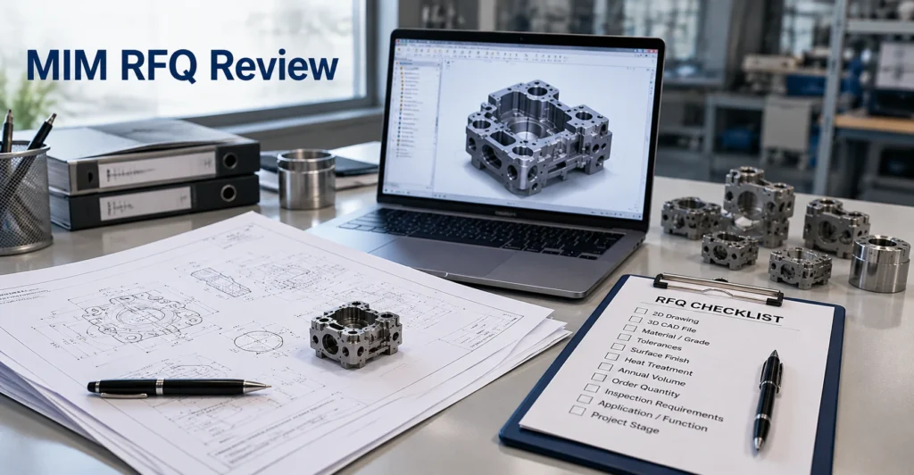
A useful MIM design review requires more than a 3D model. The supplier needs enough information to understand function, geometry, tolerances, material requirements, surface expectations, and production assumptions. Without this information, the review may become a general feasibility comment instead of a real DFM evaluation.
| File or information | Por qué es importante |
|---|---|
| Plano 2D | Confirms dimensions, tolerances, datums, notes, surface requirements, and acceptance criteria. |
| Archivo CAD 3D | Helps review geometry, parting direction, wall thickness, undercuts, ribs, and molded features. |
| Requisito de material | Defines strength, corrosion, hardness, wear, magnetic, or heat resistance needs. |
| Antecedentes de la aplicación | Helps judge load, environment, motion, assembly, and failure risk. |
| Volumen anual estimado | Helps evaluate whether MIM tooling investment is justified. |
| Requisito de acabado superficial | Affects gate mark control, polishing, tumbling, coating, passivation, or cosmetic review. |
| Dimensiones críticas | Ayuda a separar las dimensiones funcionales de las generales. |
| Current process or pain point | Helps compare MIM with CNC, PM, casting, stamping, or other manufacturing routes. |
| Heat treatment or coating needs | May affect material choice, distortion risk, surface condition, and inspection. |
| Assembly information | Helps define datums, functional faces, sliding surfaces, sealing areas, or visible zones. |
What the supplier should review
A professional MIM supplier should not only quote the drawing. Before tooling, the review should normally cover part geometry suitability for MIM, wall thickness and mass distribution, hole/slot/undercut risks, gate and parting-line-sensitive surfaces, material suitability, shrinkage compensation, sintering support, critical tolerance strategy, secondary machining, production volume, and missing RFQ information.
This review should produce engineering questions, not only a price. If a supplier quotes immediately without asking about critical dimensions, material behavior, surface requirements, or production volume, the buyer should treat the quotation as preliminary rather than tooling-ready.
Composite field scenario for engineering training: missing RFQ inputs before tooling
- ¿Qué problema ocurrió?
- A sourcing team requested a MIM quotation using only a STEP file. The supplier could estimate shape feasibility, but could not evaluate tolerance risk, material suitability, cosmetic surfaces, or annual volume economics.
- Por qué ocurrió
- The RFQ was treated as a price request instead of a design review package.
- Cuál fue la causa real del sistema
- The missing information prevented the engineering team from separating manufacturability risk from commercial assumptions.
- Cómo se corrigió
- The sourcing team provided a 2D drawing, material target, application background, estimated annual volume, and critical tolerance notes. The supplier then reviewed which features could remain as-sintered and which required additional operations.
- Cómo prevenir la recurrencia
- Before tooling or final quotation, prepare a complete review package instead of sending only a 3D model.
What You Receive After a MIM Design Review
A drawing-based MIM design review should return useful engineering feedback, not only a price. The goal is to clarify manufacturability risk, tooling concerns, tolerance strategy, missing RFQ inputs, and whether the project should continue as MIM or be compared with another route before tooling investment.
| Review output | What it helps confirm |
|---|---|
| DFM risk notes | Which features may affect injection molding, green part handling, debinding, sintering shrinkage, or inspection. |
| Tooling concern list | Gate, parting line, core pin, slide, ejector, cosmetic surface, or mold action risks that should be discussed before steel cutting. |
| Tolerance clarification | Which dimensions may remain as-sintered and which may need machining allowance, sizing, reaming, tapping, or dedicated inspection. |
| Aclaración de RFQ | Missing material, volume, surface finish, heat treatment, application, drawing, or inspection inputs that may affect quotation accuracy. |
| Process route suggestion | Whether MIM, MIM plus secondary machining, CNC machining, PM, CIM, casting, or another route should be compared before tooling release. |
Review Your MIM Design Before Tooling Starts
Before starting MIM tooling, send your 2D drawing, 3D CAD file, material requirement, critical tolerances, surface finish needs, estimated annual volume, and application background to the XTMIM engineering team. We can review whether your part geometry is suitable for MIM, which features may create tooling or sintering risk, which dimensions may require secondary machining, and what should be clarified before mold investment.
Enviar Plano para Revisión Contactar a XTMIMFAQ: MIM Design Review Before Tooling
¿La revisión de diseño MIM debe realizarse antes o después del herramental?
La revisión de diseño MIM debe realizarse antes del herramental. Una vez que el molde está construido, las decisiones relacionadas con la posición de la compuerta, la línea de partición, los pasadores de núcleo, las marcas de expulsión, la compensación por contracción y algunas estrategias de tolerancia se vuelven más difíciles de cambiar. Las correcciones posteriores al herramental aún pueden ser posibles, pero una revisión temprana generalmente brinda al equipo del proyecto más opciones técnicas.
¿Qué características de diseño deben revisarse antes del herramental MIM?
Las transiciones de espesor de pared, orificios, ranuras, socavados, paredes delgadas, nervaduras, esquinas afiladas, superficies cosméticas, puntos de referencia funcionales, tolerancias estrechas y superficies de soporte para sinterizado deben revisarse antes del herramental. Estas características pueden afectar el moldeo, el manejo de piezas en verde, el desaglutinado, la contracción, la distorsión, las operaciones secundarias y la inspección.
¿Puede el herramental MIM corregir todos los problemas de diseño después?
No. Las modificaciones al herramental pueden corregir algunos problemas, pero no siempre resuelven un balance de espesores deficiente, geometría sin soporte, estrategia de tolerancias poco clara, planificación incorrecta de superficies cosméticas o desajuste en la ruta de proceso. Algunos problemas requieren cambio de diseño, margen de maquinado, planificación de soportes o criterios de aceptación revisados.
¿La revisión temprana del diseño MIM aumenta el costo del proyecto?
La revisión temprana de diseño puede agregar discusión de ingeniería antes del herramental, pero puede reducir revisiones evitables del herramental, retrasos en pruebas, operaciones secundarias y disputas de inspección. No debe tratarse como papeleo adicional. Es un paso de control de riesgos antes de la inversión en el molde.
¿Se pueden lograr todas las tolerancias estrechas en estado sinterizado en MIM?
No siempre. La capacidad de tolerancia final depende del material, la geometría, el comportamiento de contracción, la estrategia de soporte, el tamaño de la pieza, la ubicación de la dimensión crítica y el método de inspección. Algunas características pueden permanecer tal como se sinterizan, mientras que los orificios de precisión, los puntos de referencia, las roscas o las superficies de sellado pueden requerir mecanizado secundario.
¿Qué archivos debo enviar para una revisión DFM de MIM?
Envíe un dibujo 2D, archivo CAD 3D, requisito de material, tolerancias críticas, necesidades de acabado superficial, antecedentes de la aplicación, volumen anual estimado y cualquier problema de fabricación actual. Si las superficies cosméticas o funcionales son importantes, márquelas claramente antes de la revisión del herramental.
¿Qué debe proporcionar un proveedor después de una revisión de diseño MIM?
Después de una revisión de diseño MIM, el proveedor debe proporcionar retroalimentación técnica práctica, como notas de riesgo DFM, inquietudes sobre el herramental, aclaración de tolerancias, datos faltantes en la solicitud de cotización, sugerencias de operaciones secundarias y comentarios sobre la ruta del proceso. El resultado debe ayudar al comprador a decidir si el diseño está listo para el herramental MIM o si aún necesita aclaraciones.
¿Cuándo se debe considerar otro proceso en lugar de MIM?
Se puede considerar otro proceso si la pieza es simple, de bajo volumen, grande, dominada por tolerancias de maquinado, o más adecuada para compactación PM, fundición, maquinado CNC o CIM. Se debe seleccionar MIM porque sus ventajas en geometría, material y volumen de producción se ajustan a la pieza, no solo porque la pieza sea pequeña y de metal.
Nota sobre normas y referencias técnicas
MIM design review should be guided by project-specific DFM evaluation, supplier process capability, material behavior, tooling design, shrinkage behavior, sintering support, secondary operations, and inspection requirements. Industry references such as guía 'Diseñando con MIM' de MIMA y Diseños complejos con MIM can support general discussion of MIM candidate selection, complex geometry, coring holes, gating, parting lines, and MIM-specific design principles.
MPIF Standard 35 for Metal Injection Molded Parts is mainly relevant when material standards, material classification, or property communication for MIM parts need to be discussed. It should not be treated as a substitute for project-level DFM review or as a universal rulebook for every geometry, tolerance, gate location, or sintering support decision.