
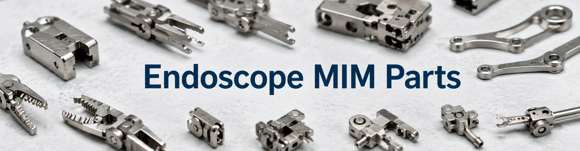
医療用MIM部品
Endoscope MIM parts are small precision metal components used inside endoscopic or minimally invasive device mechanisms, including grasper jaws, biopsy forceps components, articulation links, drive blocks, guide-channel components, locking parts and pivot features. This page focuses on component types, structure, material selection, tolerance risks and RFQ review points, not endoscopy market trends. For product engineers, the key question is whether the geometry, tolerance strategy, material requirement and expected volume justify MIM tooling, debinding, sintering shrinkage control and any required secondary operations. It helps engineers and sourcing teams judge which endoscope components are suitable for MIM, what risks should be reviewed before tooling, and what drawing information is needed for a reliable RFQ.
Metal injection molding can be a practical route when the component requires repeatable production, integrated micro features and controlled material properties after sintering. It should not be selected only because the part is small. In practice, the project must balance tooling cost, sintering shrinkage compensation, secondary machining, inspection requirements and production volume.
For broader medical component categories, review the medical MIM parts overview. For the basic process route, see 金属射出成形 および MIMプロセス 概要をご確認ください。.
Small complex metal parts with thin links, jaws, slots, holes, guide features or integrated locking geometry.
Distortion, hole shift, slot variation, edge burrs, gate marks and uncertain critical-to-function dimensions.
Start from strength, hardness, corrosion exposure, wear behavior and device-level requirements, not a generic label.
Prepare 2D drawings, 3D CAD, material notes, CTQ dimensions, surface/edge requirements and annual volume.
Manufacturing and regulatory boundary: XTMIM can review component-level MIM manufacturability, material feasibility, DFM risk, secondary operations and inspection planning. Final medical device approval, biological evaluation, cleaning validation, sterilization validation, labeling and regulatory submission remain the responsibility of the device owner or qualified medical device manufacturer.
What Endoscope MIM Parts Usually Include
Endoscope MIM parts are not complete endoscope systems. They are small metal components used inside endoscopic device mechanisms, flexible device mechanisms, graspers, biopsy tools or articulation assemblies. In practice, these parts are usually selected for MIM when they contain complex features that would be slow, costly or inconsistent to machine from bar stock.
A MIMA endoscopic device parts case study documents MIM articulation lock bars, articulation connectors, articulation drive blocks and knife guides using stainless steel MIM materials such as 17-4 and 420. This supports the real application basis for endoscope MIM components, although each commercial project still requires drawing-level review.

This image defines the page scope: small complex metal mechanism components, not complete endoscope systems, branded repair parts or general medical accessories.
Typical MIM Components Used in Endoscopic Devices
| Endoscope MIM Component | Typical Function | MIMが検討される理由 | Main Engineering Concern |
|---|---|---|---|
| Grasper jaws | Gripping, holding or manipulating small objects inside a compact device mechanism | Small teeth, cup features, curved surfaces and integrated holes | Jaw alignment, edge condition, burr control and paired inspection |
| Biopsy forceps components | Sampling, holding or closing functions in a compact mechanism | Cup-shaped geometry, thin lips, small pivot interfaces | Thin wall stability, edge consistency, mating fit and cleaning-related geometry |
| Articulation links | Transmitting motion through a small mechanism | Thin arms, holes, slots and compact linkage geometry | Sintering distortion, hole position, load direction and fatigue-sensitive zones |
| Articulation connectors | Connecting movement between mechanism parts | Small interlocking geometry and multi-axis features | Datum strategy, assembly fit, deformation risk and parting line location |
| Drive blocks | Transferring force or motion | Compact block shape, guide slots and contact faces | Slot accuracy, mating surfaces, wear zones and secondary machining need |
| Knife guides / guide components | Guiding a blade path or precision insert movement inside a mechanism | Narrow channels, edge contact and guide surfaces | Wear, burrs, edge chipping, finishing route and inspection access |
| Pivot features and small pins | Rotation or alignment inside mechanisms | Small circular features and assembly interfaces | Hole roundness, pin fit, possible reaming and functional gauge planning |
What This Page Covers and Does Not Cover
This page covers component-level MIM manufacturability for endoscope-related metal parts. It focuses on structure, material review, tolerance strategy, surface condition, edge requirements and RFQ preparation.
Scope boundary: This page does not cover complete endoscope assembly, optical systems, electronic modules, branded replacement parts, clinical performance, sterilization validation or medical device approval. Those topics belong to the device manufacturer, regulatory owner or complete medical device development team.
Why MIM Is Used for Small Endoscopic Device Components
MIM is useful for endoscopic device components when the part combines small size with geometric complexity. The process starts with fine metal powder mixed with binder to form feedstock. The feedstock is injection molded, the green part is handled carefully, the binder is removed through debinding, and the part is sintered to reach final density and dimensions. Because the molded part shrinks during sintering, the tool must compensate for shrinkage, and critical dimensions must be reviewed before tooling.
The 金属射出成形のEPMA概要 describes MIM as a process for complex-shaped parts in high quantities and explains why the route becomes less attractive when a part can be made economically by simpler powder metallurgy or machining routes. This matters for endoscope components because MIM should be selected for geometry and production logic, not simply because the part is small.
小型複雑形状
Endoscope components often include small holes and pivot interfaces, thin arms and link sections, cup-shaped jaw geometry, guide slots, internal channels, small teeth, compact three-dimensional surfaces and integrated locating or locking features. A common mistake is to judge only the outer size of the part. From a design review perspective, the real issue is whether internal features, thin regions, parting line, gate location and sintering support strategy can be controlled together.
Repeatable Production After Tooling
MIM becomes more attractive when the design is stable and the annual demand can justify tooling. Once the tooling, feedstock, debinding, sintering and inspection route are validated, the process can support repeatable production of complex small parts.
This does not mean every endoscope part should be made by MIM. If the part is still in early prototype iteration, or if only a few pieces are needed, CNC machining or other prototype methods may be more practical before committing to MIM tooling.
Reduced Machining for Difficult Features
MIM can reduce machining when the part contains complex molded features that can be formed near-net shape. Examples include small jaw profiles, integrated link shapes, compact drive blocks or guide features. However, critical holes, slots, sharp edges or contact surfaces may still require secondary machining, sizing, polishing, deburring or inspection fixtures.
Engineering question: The correct question is not “Can MIM avoid all machining?” The better question is which features can be molded reliably, which features must be corrected after sintering, and whether the combined route still improves cost, repeatability or design freedom compared with full machining.
When MIM Becomes a Better Fit Than CNC or Stamping
MIM may be a better fit when the geometry is too complex for economical CNC machining, multiple machined features can be integrated into one molded component, part size is small enough for MIM economics, production volume supports tooling investment, the material is available as a suitable MIM feedstock, and critical features can be controlled by a combined tooling, sintering and inspection strategy.
MIM may not be the best first choice if the part is large, simple, low-volume, frequently changing, or defined by ultra-tight dimensions that would require extensive post-machining.
Common Endoscope MIM Part Types and Design Features
This is the most important section for engineers evaluating endoscope MIM parts. The part name alone does not determine suitability. MIM suitability depends on wall thickness, feature transition, gate location, shrinkage behavior, sintering support, material choice, secondary operation allowance and inspection method.
Grasper Jaws and Biopsy Forceps Components
Grasper jaws and biopsy forceps components are often strong candidates for MIM when they contain small teeth, cup geometry, curved profiles, thin lips, pivot holes and paired mating surfaces.
- Whether the left and right jaws close symmetrically.
- Whether thin lips can survive debinding and sintering without distortion.
- Whether teeth or cup features can be molded and finished without harmful burrs.
- Whether pivot holes need post-sintering machining.
- Whether edge condition must be polished, radiused or inspected.
In production, jaw alignment is usually more important than the general outer profile. A jaw that meets outer dimensions but does not close correctly may fail assembly or function.
Articulation Links and Connectors
Articulation links and connectors are used to transfer movement through compact endoscopic mechanisms. They may include thin arms, small holes, slots, hooks, shoulders and interlocking features.
MIM can be suitable when the linkage geometry is difficult to machine repeatedly. The main risk is distortion during debinding and sintering. Thin arms and asymmetric geometry may warp if support strategy, gate location and shrinkage compensation are not reviewed early. For more geometry-specific review, see MIM焼結サポート.
Drive Blocks and Motion Transfer Components
Drive blocks are compact parts that transfer force or motion within an endoscope mechanism. These parts may include guide surfaces, slots, pockets, shoulders, contact faces and small locating features.
The MIM review should identify which surfaces are functional and which surfaces are non-critical. If a guide slot controls movement, the slot may require tighter process control or secondary machining. If the drive block contacts another moving component, wear, surface finish and edge condition should be reviewed together with material selection.
Knife Guides and Cutting-Path Components
Knife guides and cutting-path components may include narrow channels, blade guide surfaces, contact edges and wear-prone zones. MIM can form compact guide geometry, but edge and slot requirements must be defined clearly.
A common mistake is to specify a sharp edge without explaining its function. In MIM, extremely sharp edges can be difficult to mold, debind, sinter and finish consistently. If the edge is functional, the drawing should define the edge condition, burr limit, radius expectation or secondary finishing requirement.
Pivot Features, Small Pins and Rotating Interfaces
Endoscope mechanisms often include small pivot holes, pins, rotating interfaces and alignment features. MIM can produce the surrounding geometry, but pivot fit is often assembly-driven. The review should confirm whether the pivot hole can remain as-sintered or requires reaming, drilling, sizing or inspection after sintering. For general cross-industry pin and shaft structures, see MIM shafts and pins for pivot features.
Structural Features That Need DFM Review Before Tooling
Endoscope MIM components should be reviewed before tooling because small design choices can affect mold filling, debinding stability, sintering shrinkage, distortion, burr formation and inspection repeatability. For a broader review route, see the MIM DFM review before tooling.

Feature-level review is essential because the overall part size does not guarantee stable molding, debinding, sintering or final assembly fit.
Thin Arms and Long Slender Features
Thin arms are common in articulation links and small mechanical connectors. The risk is not only breakage; the larger issue is dimensional movement during debinding and sintering. Thin features may bend, twist or shrink unevenly if the geometry is not balanced.
- Minimum wall section and transition areas.
- Gate position and flow path.
- Support direction during sintering.
- Fixture or setter requirement.
- Inspection datum strategy.
- Whether the feature is load-bearing or only locating.
Small Holes, Slots and Pivot Interfaces
Small holes and slots are common in jaws, links, drive blocks and pivot features. They may be molded, machined, reamed or finished depending on tolerance and function. For additional design guidance, review MIM holes, slots and undercuts.
| フィーチャー | Typical Risk | 金型着手前のレビュー |
|---|---|---|
| Small pivot hole | Shrinkage variation, roundness, assembly fit | Hole size, datum, reaming allowance |
| Narrow slot | Width variation, distortion, burrs | Slot function, secondary machining need |
| Long guide channel | Warpage, contact inconsistency | Support strategy, material, finishing |
| Cross-hole | Tooling complexity, flash risk | Mold action, parting line, inspection access |
| Paired hole pattern | Misalignment during assembly | Datum scheme, functional gauge possibility |
Teeth, Edges and Cup-Shaped Features
Teeth and cup-shaped features are common in grasper jaws and biopsy forceps components. These features affect function, but they also create molding and finishing challenges. The drawing should clarify whether the edge is used for cutting, gripping, alignment or clearance. Each function leads to a different manufacturing review.
Undercuts, Parting Lines and Gate Location
Undercuts, parting lines and gate location influence mold complexity and visible or functional surface quality. In endoscope parts, a gate mark or parting line should not be placed on a critical sliding surface, jaw contact edge, pivot interface or sealing-related surface without review.
焼結支持と変形リスク
Sintering distortion is one of the most important risks in thin endoscope MIM components. Because the part shrinks during sintering, thin arms, asymmetric features and uneven mass distribution may cause dimensional movement. The review should consider how the part will be oriented and supported during sintering, not only how it will be molded.
Material Selection for Endoscope MIM Components
Material selection for endoscope MIM parts should begin with component function, not with a generic “medical grade” label. The same endoscope assembly may contain parts with different requirements: strength, hardness, corrosion resistance, wear resistance, edge stability or ductility.

A drive block may be strength-driven, a guide component may need wear and hardness review, while a corrosion-focused small component may require a different stainless steel choice.
The MIMA endoscopic device case confirms that MIM 17-4 and MIM 420 have been used in a real endoscopic device component set, but this should not be interpreted as a universal material recommendation. Material choice must follow drawing requirements, device-level validation needs and supplier-specific process capability.
For broader material comparison, review MIM材料 および MIM stainless steel material options.
Material selection caveat: The materials below are candidate options, not fixed recommendations for every endoscope component. Final selection should consider load direction, hardness target, corrosion exposure, mating parts, edge condition, heat treatment, surface finishing, customer specification and device-level validation requirements.
| 材料 | Possible Endoscope Part Use | Review Boundary |
|---|---|---|
| 17-4 PHステンレス鋼 | Articulation links, drive blocks, locking parts, structural connectors | Strength, heat treatment, dimensional change, corrosion expectations |
| 420ステンレス鋼 | Guide components, contact surfaces, locking features, selected jaw features | Hardness, edge condition, corrosion trade-off, finishing route |
| 316Lステンレス鋼 | Corrosion-focused small components where high hardness is not the main driver | Lower hardness, wear review, deformation and strength requirements |
| 440Cステンレス鋼 | Higher hardness or wear-related requirements | Brittleness risk, edge chipping, corrosion review, sliding contact |
17-4 PH Stainless Steel for Strength-Driven Components
17-4 PH stainless steel may be considered for strength-driven endoscope components such as articulation links, drive blocks, locking parts or structural connectors. It is often reviewed when the part needs higher strength than a softer corrosion-focused stainless steel.
420 Stainless Steel for Hardness and Contact Features
420 stainless steel may be considered for components that need hardness, wear resistance or stable contact surfaces, such as guide components, locking interfaces or selected jaw features. The trade-off is that hardness-focused materials require careful review of edge condition, brittleness risk, corrosion expectations and finishing route.
316L Stainless Steel for Corrosion-Focused Components
316L stainless steel may be considered when corrosion resistance, ductility or general medical device material familiarity is more important than high hardness. However, 316L may not be ideal for wear-heavy guide surfaces, sharp contact edges or parts requiring high hardness.
440C Stainless Steel for Higher Wear or Hardness Requirements
440C stainless steel may be reviewed for higher hardness or wear-related requirements. It should be evaluated carefully when the component includes thin edges, shock loading, sliding contact or corrosion exposure. In some designs, a lower-hardness material with secondary finishing may be more practical than choosing the hardest available alloy.
材料の境界: The MIM supplier can support material and process feasibility review, but final device-level biological evaluation, cleaning validation, sterilization validation and regulatory strategy remain the responsibility of the device owner or qualified medical device manufacturer.
Tolerance, Surface and Edge Requirements for Endoscope MIM Parts
Endoscope MIM components often fail not because the general shape is impossible, but because the critical dimensions are not separated from non-critical dimensions. A good drawing should identify which dimensions control motion, alignment, mating, gripping, blade guidance or inspection acceptance. For general process capability boundaries, see MIM公差.

Endoscope MIM part inquiries should be based on drawings, critical dimensions and inspection requirements, not only part names.
Critical Dimensions Are Usually Assembly-Driven
Critical dimensions may include pivot hole position, jaw spacing, slot width, mating surface flatness, pin fit, guide channel width or paired component alignment. These dimensions should be reviewed against the actual assembly function.
| 要件 | 一般的な懸念事項 | エンジニアリングレビュー |
|---|---|---|
| Pivot hole position | Motion and alignment | Datum, reaming need, inspection method |
| Jaw closing alignment | Gripping or cutting function | Paired inspection, edge finishing |
| Slot width | Guide or drive fit | As-sintered capability vs machining |
| Contact surface | Wear and motion transfer | Material, finishing, inspection |
| Edge radius | Functional edge or safety requirement | Burr limit, polishing, drawing clarity |
When Secondary Machining May Be Required
Secondary machining may be required when the tolerance is tighter than what should be controlled as-sintered, when a hole must fit a precision pin, when a guide slot controls movement, or when a contact surface requires consistent finish. This does not mean the part is unsuitable for MIM. In many cases, the best route is MIM for the complex base geometry plus secondary machining for selected critical features.
Edge Radius, Burr Control and Contact Surfaces
Endoscope components may include functional edges, gripping teeth, guide surfaces or sliding interfaces. The drawing should define whether the edge must be sharp, broken, polished, radiused or burr-free within a functional limit. A vague note such as “no burr” is often not enough. The buyer should specify where burrs matter most, what surfaces contact mating parts, and whether polishing or passivation is expected.
Surface Finish and Cleaning-Related Geometry
For medical device components, surface condition can affect assembly, motion, cleaning-related design considerations and device-level validation. The MIM component supplier can review surface finish feasibility, but final cleaning and sterilization requirements should be confirmed by the device owner.
Medical Device Compliance and Validation Boundaries
Endoscope MIM parts should be discussed carefully because they may be used in medical devices, but the MIM component itself is not the same as a finished, validated medical device.
FDA guidance on reprocessing reusable medical devices focuses on the formulation and scientific validation of reprocessing instructions for reusable devices. This supports the point that cleaning, disinfection, sterilization and labeling validation belong to the device-level development and regulatory process, not to a generic component page.
XTMIM Reviews Component Manufacturability, Not Complete Device Approval
XTMIM can review whether a metal part is suitable for MIM based on geometry, material, tolerance, secondary operations, surface finishing and inspection. XTMIM should not claim that an endoscope component is automatically approved for medical use.
Biocompatibility, Cleaning and Sterilization Need Device-Level Validation
FDA guidance on ISO 10993-1 biological evaluation explains the use of biological evaluation within a risk management process to support medical device applications. This means material and biological safety evaluation must be handled in the context of the final device, body contact, duration, processing and intended use.
What Buyers Should Confirm Before Production
- Material requirement and applicable standard.
- Whether the part contacts tissue, fluid, instrument channels or other device elements.
- Cleaning, sterilization or passivation expectations.
- Critical dimensions and inspection plan.
- Traceability and documentation needs.
- Whether the component is prototype, validation build or production part.
When MIM May Not Be Suitable for Endoscope Components
MIM is not always the correct route. A credible project review should identify unsuitable cases early, before tooling cost is committed.
Very Low Annual Volume
If the project only requires a few prototypes or uncertain early-stage samples, CNC machining, additive manufacturing or manual fabrication may be more practical for the first design iteration. MIM becomes stronger when the design is stable and production volume can support tooling.
Oversized or Simple Machined Components
If the endoscope component is large, simple, flat or easily machined, MIM may add unnecessary tooling cost and process complexity. Simpler shapes may not justify MIM economics.
Extremely Tight Features That Require Full Machining
If most of the part’s important surfaces require precision machining after sintering, MIM may not create enough value. In those cases, a machined route or a hybrid manufacturing strategy should be reviewed.
Uncontrolled Thin Sections or Sharp Internal Corners
Very thin unsupported arms, sharp internal corners, abrupt wall transitions and narrow fragile edges can create molding, debinding and sintering problems. These features may still be possible, but they should be reviewed and modified before tooling.
Composite Field Scenario: Articulation Link Distortion
発生した問題: A small articulation link design showed inconsistent hole alignment after sintering. The outer profile appeared acceptable, but the link did not assemble smoothly with the mating mechanism.
発生理由: The link had thin arms, asymmetric mass distribution and small pivot holes close to a transition zone. The original drawing focused on nominal hole size but did not define enough functional datum information.
真のシステム原因: The issue was not only the hole diameter. The real cause was the combination of sintering distortion, weak datum definition, thin-arm geometry and insufficient review of how the part would be supported during sintering.
修正方法: The design review adjusted the datum strategy, identified which hole required secondary finishing, reviewed sintering support orientation and clarified which surfaces were functional.
再発防止策: For similar articulation links, the drawing should identify critical hole patterns, mating components, load direction, support-sensitive surfaces and inspection method before tooling.
Composite Field Scenario: Guide Slot Control
発生した問題: A guide component concept included a narrow guide slot with a functional edge, but the drawing did not clearly separate guide width, edge condition and burr requirement.
発生理由: The design team assumed the slot could be molded to final functional condition without secondary finishing.
真のシステム原因: The slot was both a molded feature and a functional guide surface. The edge requirement, wear expectation and inspection method were not defined early.
修正方法: The review classified the slot as a critical-to-function feature, added secondary finishing allowance, clarified edge condition and selected a material route based on contact and wear expectations.
再発防止策: For guide-channel components, slot function, edge condition, burr allowance, material hardness and post-sintering finishing should be reviewed together before tooling.
Endoscope MIM Part RFQ and Drawing Review Checklist
A strong RFQ package helps the engineering team review manufacturability before tooling instead of discovering problems during trial production.
What to Provide for a DFM Review
| RFQ入力項目 | 重要性 |
|---|---|
| 2D図面 | Defines dimensions, tolerances, material and notes. |
| 3D CADファイル | Helps evaluate geometry, tooling, gate and shrinkage. |
| 材料要件 | Guides feedstock and heat treatment review. |
| Critical-to-quality dimensions | Separates pivot holes, slot width, jaw alignment, mating faces and burr-sensitive edges from general dimensions. |
| 表面仕上げ要件 | Affects polishing, deburring and inspection route. |
| Edge or burr requirement | Important for jaws, guide surfaces and contact features. |
| 相手部品情報 | Helps review assembly fit, motion, pivot clearance and contact surfaces. |
| 年間数量 | MIM金型が経済的に妥当かどうかを判断します。. |
| 適用背景 | Helps identify load, wear, corrosion or cleaning concerns. |
| 試作段階または量産段階 | Affects process recommendation and risk level. |
What XTMIM Engineers Will Check
- Whether the geometry is suitable for MIM.
- Whether wall thickness and transitions are reasonable.
- Whether holes, slots and undercuts are moldable or need secondary operations.
- Where gates and parting lines may be placed.
- Whether sintering support may affect critical dimensions.
- Whether the material is suitable for the function.
- Which dimensions should be inspected as critical-to-function.
- Whether secondary machining, polishing, passivation or heat treatment may be required.
Typical Questions Before Tooling
- Which dimensions control assembly?
- Which edges are functional?
- Which surfaces contact moving parts?
- Is the component reusable or single-use?
- Is the part in prototype validation or production planning?
- Are there cleaning, passivation or surface requirements?
- What annual quantity is expected?
- Are mating parts available for review?
Request an Endoscope MIM Component Review
If your endoscope component includes small jaws, articulation links, drive blocks, guide components, pivot holes, thin arms, narrow slots or functional edges, send your drawing package for a MIM manufacturability review.
Please provide 2D drawings, 3D CAD files, material requirements, tolerance requirements, CTQ dimensions, surface finish expectations, edge or burr requirements, mating part information, estimated annual volume and application background. XTMIM engineers can review MIM suitability, tooling risk, sintering distortion risk, material options, secondary machining needs, inspection strategy and open issues before tooling, trial production or production planning.
規格および技術参考に関する注記
The external references used on this page support topic scope and engineering boundaries. They do not replace project-specific drawings, material specifications, customer requirements, medical device risk management or formal regulatory review.
| Reference | Why It Is Relevant Here | How It Should Be Used |
|---|---|---|
| MIMA Endoscopic Device Parts Case Study | Documents real endoscopic device components made by metal injection molding, including articulation and guide components. | Supports application relevance, not a universal material choice, performance guarantee or medical approval claim. |
| EPMA金属射出成形概要 | Explains MIM as a route for small complex parts and clarifies selection boundaries versus simpler routes. | Supports process selection logic and “when not to use MIM” decisions. |
| FDA Reprocessing Medical Devices Guidance | Clarifies that cleaning and reprocessing validation are device-level responsibilities. | Supports cautious language around reusable device validation and labeling; it is not a component-level certification claim. |
| FDA ISO 10993-1 Biological Evaluation Guidance | Explains biological evaluation within a medical device risk management process. | Supports the boundary that biocompatibility claims must be handled at device level. |
For production projects, the applicable material standards, inspection methods, surface finishing requirements, traceability needs and regulatory documents should be confirmed by the device owner and qualified regulatory or quality teams before tooling or production approval.
FAQ: Endoscope MIM Parts
Can MIM be used for endoscope grasper jaws?
Yes, MIM can be considered for endoscope grasper jaws when the part includes small teeth, cup geometry, pivot holes, curved surfaces or integrated features that are difficult to machine efficiently. The key review points are jaw alignment, edge condition, burr control, material selection and whether any critical holes or contact surfaces require secondary finishing.
What endoscope components are commonly suitable for MIM?
Common candidates include grasper jaws, biopsy forceps components, articulation links, articulation connectors, drive blocks, guide components, locking parts and small pivot features. Suitability depends on geometry, wall thickness, tolerance, material, production volume and inspection requirements.
Which stainless steels are used for endoscope MIM parts?
Possible stainless steels include 17-4 PH, 420, 316L and 440C, depending on the part function. 17-4 PH may be reviewed for strength-driven components, 420 for hardness or contact features, 316L for corrosion-focused parts and 440C for higher hardness or wear requirements. Final material selection must follow the drawing, application and device-level requirements.
Can MIM achieve tight tolerances for pivot holes and slots?
MIM can produce small holes and slots, but tight functional tolerances may require secondary machining, reaming, sizing or special inspection. Pivot holes, guide slots and mating surfaces should be identified as critical-to-function dimensions before tooling.
Do endoscope MIM parts require secondary machining?
Some endoscope MIM parts can be used as-sintered for non-critical features, but critical holes, slots, guide surfaces, contact faces or edges may require secondary machining or finishing. The best approach is to define which features must be controlled after sintering.
Is MIM suitable for low-volume endoscope prototypes?
MIM is usually not the first choice for very low-volume prototypes because it requires tooling. CNC machining or additive manufacturing may be more practical during early design iteration. MIM becomes more suitable when the design is stable and production volume supports tooling investment.
Who is responsible for medical device validation and biocompatibility testing?
The device owner or qualified medical device manufacturer is responsible for final device-level validation, biocompatibility evaluation, cleaning validation, sterilization validation and regulatory submission requirements. XTMIM can support component-level MIM manufacturability review, material feasibility review and inspection planning.
Does XTMIM provide medical device certification for endoscope MIM parts?
No. XTMIM supports component manufacturing review, MIM process feasibility, material feasibility, secondary operation planning and inspection review. Final medical device certification, regulatory submission, biological evaluation, cleaning validation and sterilization validation must be handled by the device owner or qualified medical device manufacturer.
What information should I provide for an endoscope MIM part quotation?
Provide 2D drawings, 3D CAD files, material requirements, critical dimensions, surface finish expectations, edge or burr requirements, mating part information, annual volume and application background. This helps the engineering team review MIM suitability, tooling risk, secondary operations and inspection requirements.