
High Precision MIM Parts for Small, Complex Metal Components
High precision MIM parts are small, complex metal components where selected functional dimensions, mating features, holes, slots, gears, shafts, brackets, or assembly surfaces must remain stable through molding, debinding, sintering, secondary operations, and final inspection. Metal injection molding can be a strong option when a part is too complex or costly for multi-operation CNC machining, but “high precision” in MIM does not mean tightening every dimension on the drawing. In practice, precision depends on critical dimension classification, tooling compensation, feedstock stability, green part handling, sintering shrinkage control, support strategy, material behavior, targeted secondary operations, and inspection planning. This page helps engineers and sourcing teams decide whether a precision metal part is suitable for MIM, which features need special review, and what information should be confirmed before tooling.
Quick Navigation
What High Precision Means in MIM Parts
High precision in metal injection molding is not only a tolerance number. It is a manufacturing result created by the relationship between part geometry, tooling design, feedstock behavior, injection molding stability, green part handling, debinding, sintering shrinkage, secondary operations, and final inspection.
A common mistake is to evaluate MIM precision as if it were CNC machining precision. CNC removes material from a solid block and can finish selected surfaces directly by cutting, grinding, or reaming. MIM forms a near-net-shape green part from fine metal powder and binder, removes the binder, and then sinters the part to high density. During sintering, the part shrinks, so the tooling must compensate for the expected dimensional change. This is why precision MIM projects need drawing-based review before tooling.
From a design review perspective, the first question is not “Can every dimension be very tight?” The better question is: which dimensions are critical to function, assembly, movement, sealing, positioning, or inspection? This distinction affects tooling cost, secondary machining scope, inspection planning, and production repeatability.
Precision in MIM Is Not Only a Tolerance Number
Precision MIM projects should separate dimensions into different levels of importance. Without this classification, drawings can become unnecessarily expensive to manufacture and difficult to inspect.
| Abmessungstyp | Bedeutung | MIM Review Priority |
|---|---|---|
| Funktionskritische Maße | Dimensions that affect fit, movement, sealing, alignment, gear meshing, or assembly | Highest |
| Important dimensions | Dimensions that affect assembly repeatability, appearance consistency, or installation | Mittel |
| Reference dimensions | Dimensions used for drawing communication but not normally inspected as functional dimensions | Niedrig |
| Unkritische Maße | Dimensions that do not affect part function or assembly | Keep tolerance realistic |
As-Sintered Precision vs Secondary Precision
Some MIM parts can meet most dimensions in the as-sintered condition. Other parts need secondary operations for selected features. For more detail on machining, sizing, coining and finishing after sintering, see our secondary operations for critical MIM dimensions Seite.
| Precision Type | Bedeutung | Typische Anwendung |
|---|---|---|
| As-sintered precision | Dimensions achieved after sintering without further machining | Outer shape, general holes, non-critical surfaces |
| Critical feature precision | Selected dimensions that control assembly or function | Pin holes, gear bores, slots, shafts, datum surfaces |
| Secondary precision | Local dimensions improved after sintering | Reamed holes, ground surfaces, machined sealing faces |
| Functional precision | Precision judged by assembly or working performance | Gear meshing, hinge rotation, shaft fit, bracket alignment |
How to Set Realistic MIM Tolerance Expectations
For precision MIM parts, tolerance expectations should be set by feature class instead of applying the same tight tolerance to the whole drawing. A realistic review separates dimensions that can remain as-sintered from dimensions that may need sizing, machining, grinding, reaming, or functional gauging.
| Merkmalstyp | Typical Tolerance Strategy | Technischer Prüfpunkt |
|---|---|---|
| General outside shape | Often reviewed as as-sintered geometry | Check shrinkage direction, wall thickness balance and non-critical dimensions. |
| Functional holes, bores and slots | May be as-sintered, sized, reamed or machined depending on fit requirement | Confirm mating part, datum reference, gauge method and whether local post-processing is needed. |
| Shaft diameters and rotating features | Usually reviewed as critical fit surfaces | Check roundness, straightness, length-to-diameter ratio and secondary finishing requirement. |
| Flat sealing or datum surfaces | May require secondary machining or grinding | Confirm flatness, surface finish, sealing risk and inspection method before tooling. |
| Cosmetic and exposed surfaces | Reviewed together with gate location, parting line and finishing allowance | Separate cosmetic zones from functional zones to avoid tooling and finishing conflicts. |
Common High Precision MIM Parts We Manufacture
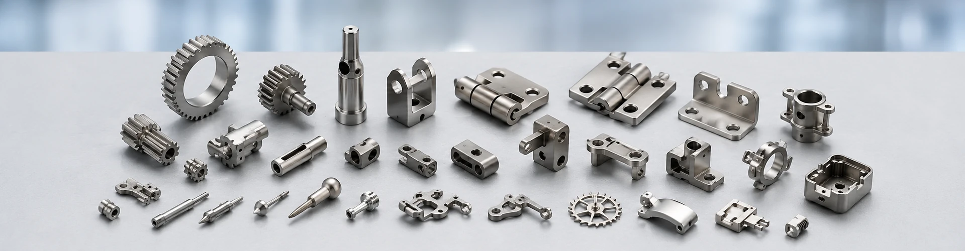
High precision MIM parts appear across consumer electronics, medical devices, dental hardware, robotics, drones, automotive mechanisms, industrial equipment, and wearable devices. The page focus, however, is not the industry itself. The shared engineering logic is that the part is small, complex, difficult to machine economically, and contains features that require stable dimensional control.

Precision Motion and Transmission Parts
Typical parts include MIM gear parts, micro gears, pinions, sector gears, ratchet parts, pawls, cams, levers and miniature transmission parts.
Key concerns include tooth profile, bore fit, concentricity, mating surface consistency, heat treatment response and wear behavior. For gear-specific design and application considerations, see precision MIM gear parts.
Precision Shafts, Pins and Rotating Parts
Typical parts include MIM shafts, precision pins, hinge pins, pivot pins, miniature axles, guide pins and lock pins.
Key concerns include diameter, roundness, straightness, fitting surface and length-to-diameter ratio. A short pin with complex molded features may fit MIM; a long slender shaft may need another process or targeted secondary finishing. See MIM shafts and pins with critical fit surfaces.
Precision Hinge and Folding Mechanism Parts
Typical parts include hinge barrels, hinge arms, rotating brackets, laptop hinge parts, phone hinge parts and compact folding mechanism parts.
The real issue is not only the individual part dimension. Assembly clearance, friction zone, pin hole accuracy, repeated movement and wear surfaces must be reviewed together. See MIM hinge parts for compact mechanisms.
Precision Brackets and Mounting Hardware
Typical parts include miniature brackets, mounting plates, sensor brackets, support arms, locating blocks, alignment brackets and fixing clips.
Key concerns include hole position, flatness, datum surfaces, screw boss stability and assembly alignment. Thin walls or large flat areas can increase sintering distortion risk. See precision MIM bracket parts.
Precision Medical and Dental MIM Parts
Typical parts include endoscope parts, surgical instrument parts, dental brackets, dental tool parts, orthodontic components and miniature medical hardware.
Material selection, cleaning accessibility, surface condition and inspection requirements should be reviewed carefully. This page discusses manufacturability and precision control, not medical device approval. Related pages include medizinische MIM-Teile, endoscope MIM parts und dental MIM parts.
Electronics, Wearable, Robotics and Industrial Parts
Typical parts include mobile phone metal parts, laptop hinge parts, wearable device hardware, watch case parts, robot joint parts, drone locking parts, valve parts and sensor housings.
These parts often combine compact geometry, repeated movement, appearance zones and functional interfaces. Related pages include MIM-Teile für Unterhaltungselektronik, wearable device MIM parts, robotics MIM parts, drone MIM parts und MIM-Teile für Industrieanlagen.
High Precision MIM Part Examples and Engineering Concerns
The table below helps identify whether a precision part is likely to fit MIM and what should be reviewed before tooling. It is not a substitute for drawing review, because the same part name can have very different tolerance, material, surface and inspection requirements.
| Teiletyp | Common Precision Concern | MIM-Eignung | Prüfung vor dem Werkzeugbau |
|---|---|---|---|
| MIM-Zahnräder | Tooth profile, bore fit, meshing accuracy | High when the gear is small and complex | Gear datum, bore tolerance, heat treatment |
| Micro gears and pinions | Small teeth, concentricity, wear surface | Good for compact mechanisms | Tooling feasibility, inspection method |
| Wellen und Stifte | Diameter, straightness, fitting surface | Good for short parts with added features | Length-to-diameter ratio, secondary machining need |
| Scharniere | Pin hole, rotating fit, friction zone | Good for compact hinge hardware | Clearance, wear surface, assembly gap |
| Halterungen | Hole position, flatness, datum alignment | Good for complex mounting geometry | Datum scheme, wall thickness, screw boss |
| Endoscope parts | Micro features, thin sections, small slots | Good for small complex metal parts | Small slot risk, material, surface condition |
| Dental parts | Fit, miniature geometry, surface condition | Good when material and tolerance are reviewed | Surface finish, fitting interface |
| Watch case parts | Cosmetic surface, fit zones, buttons | Case-by-case | Parting line, gate location, polishing allowance |
| Mobile phone parts | Compact structure, thin wall, assembly fit | Good for small structural hardware | Cosmetic zone, strength, assembly fit |
| Robotikteile | Joint fit, repeated movement, load path | Good for compact loaded parts | Hole position, wear zone, mechanical load |
| Drone parts | Lightweight precision hardware | Good for compact complex parts | Weight, wall thickness, impact area |
| Valve and pump parts | Sealing, flow path, fit | Case-by-case | Sealing surfaces may need machining |
| Sensor-Gehäuse | Assembly fit, small holes, flatness | Good for compact housings | Hole accuracy, flatness, surface needs |
When MIM Is Suitable for High Precision Parts
MIM is not chosen only because a part is “precision.” It is chosen when precision, complexity, material performance, and production volume make the process economically and technically reasonable.
Suitable Conditions
- The part is small or miniature.
- The geometry is complex enough to justify tooling.
- The part includes holes, slots, steps, undercuts, thin walls, or small features.
- CNC machining would require multiple setups or difficult tool access.
- Production volume can justify the upfront tooling and engineering review.
- The part needs stainless steel, low alloy steel, soft magnetic alloy, titanium alloy, cobalt-chromium alloy, or another MIM-compatible material.
- Only selected functional dimensions require tight control.
- Secondary operations are acceptable for critical features when as-sintered accuracy is not enough.
Why MIM Can Reduce Precision Part Cost
For small complex metal parts, CNC machining may require multiple setups, special fixtures, tool access compromises, and high material waste. MIM can reduce unit cost at volume by forming complex geometry near net shape. The value becomes stronger when one MIM part can replace several machined, stamped, or assembled components.
However, MIM has upfront tooling and engineering costs. It is usually not the best choice for one-off prototypes or very low-volume parts unless the design is being developed for future production.
When High Precision Parts Should Not Use MIM
A professional MIM supplier should also explain when MIM is not the best choice. This prevents tooling risk, unrealistic tolerance expectations and unnecessary project cost.
| Not Ideal for MIM | Grund |
|---|---|
| Prototyp mit sehr geringer Stückzahl | Tooling cost is usually not justified. |
| Large simple block part | CNC, casting, forging, or stamping may be more suitable. |
| Ultra-tight tolerance on every dimension | MIM should focus on critical dimensions, not unnecessary drawing-wide tight tolerance. |
| Long unsupported thin part | Sintering distortion risk may be high. |
| Large flat sealing surface | Secondary machining or another process may be needed. |
| Part requiring no gate mark or parting line | Cosmetic and functional surfaces must be reviewed before tooling. |
| Design cannot accept shrinkage compensation | MIM depends on tooling compensation and sintering control. |
What Controls Dimensional Accuracy in MIM
Dimensional accuracy in MIM is controlled by the full process chain, not by one production step. This matters because a dimensional issue found after first trial parts may come from tooling compensation, molding stability, green part handling, debinding, sintering support, secondary operation planning, or inspection definition.

Tooling Compensation and Shrinkage Control
MIM parts shrink during sintering. The mold cavity is therefore designed larger than the final part, and the tooling must compensate for expected shrinkage. This compensation depends on material, part geometry, wall thickness, feature distribution, and sintering behavior.
For precision parts, the mold design should be reviewed around datum surfaces, critical holes, fitting features, gear bores, shaft surfaces, and assembly interfaces. If critical features are not identified before tooling, later correction may require expensive tool modification or secondary machining.
Feedstock, Injection Molding and Green Part Stability
MIM feedstock contains fine metal powder and binder. Feedstock consistency affects injection stability, part density distribution, and repeatability. During injection molding, poor flow, trapped air, weld lines, or short shots can affect local geometry and strength.
Green parts are fragile before sintering. Handling, trimming, degating, and tray loading can affect edge quality, deformation, and crack risk. For small high precision parts, green part handling should not be treated as a minor step.
Debinding, Sintering and Support Strategy
Debinding removes binder before sintering. If debinding is not controlled properly, the part may crack, deform, or retain contamination. During sintering, the part densifies and shrinks. Long thin sections, unsupported flat surfaces, cantilever features, and uneven wall thickness can distort.
Sintering support and part orientation are important for dimensional stability. In some cases, support strategy can be as important as tooling design.
Secondary Operations for Critical Dimensions
Secondary operations may be used when selected features require tighter control than the as-sintered process can provide. Common options include sizing, coining, drilling, reaming, tapping, CNC machining, grinding, polishing, heat treatment and surface finishing.
Not every high precision MIM part needs secondary operations. The best approach is to review which dimensions are functional and decide whether they should be molded, sintered, sized, machined, or inspected with a functional gauge.
Critical Dimensions, Tolerances and Secondary Operations
For precision MIM parts, tolerance strategy should be feature-based. The goal is not to make every dimension tight. The goal is to protect the dimensions that control fit, motion, sealing, datum alignment, appearance zone, or inspection acceptance.

Precision Risk by Feature Type
| Merkmal | Precision Risk | Prüfpunkt |
|---|---|---|
| Kleine Löcher | Shrinkage, ovality, incomplete forming | Hole size, depth, post-machining need |
| Dünne Wände | Distortion, incomplete filling | Wall thickness, flow path, support |
| Lange Stifte oder Wellen | Bending, straightness loss | Length-to-diameter ratio, sintering support |
| Zahnräder | Tooth form, bore concentricity | Datum, bore, heat treatment, inspection |
| Flat mounting faces | Warpage, flatness deviation | Support strategy, secondary machining |
| Slots and grooves | Deformation, corner stress | Radius, depth, molding direction |
| Gewindemerkmale | Strength and accuracy risk | Molded thread vs tapped thread |
| Kosmetische Oberflächen | Gate mark, parting line, polishing effect | Cosmetic zone definition |
| Dichtflächen | Leakage risk, flatness, surface finish | Machining or grinding requirement |
Practical Tolerance Review Questions
- Which dimensions affect function?
- Which surfaces control assembly?
- Which holes or shafts require fit?
- Which surfaces are cosmetic?
- Welche Abmessungen können im gesinterten Zustand verbleiben?
- Which dimensions may need secondary operations?
- Which inspection method should be used?
Composite Field Scenario for Engineering Training: Tight Hole Tolerance in a Compact Bracket
Welches Problem ist aufgetreten: A compact MIM bracket had several mounting holes. The customer marked all holes with very tight tolerances, although only two holes controlled assembly alignment.
Warum es passiert ist: The drawing treated every hole as equally critical, so the early cost estimate assumed unnecessary secondary machining for all holes.
Was die eigentliche Systemursache war: The issue was not only hole accuracy. The real cause was poor critical dimension classification. The drawing did not separate alignment holes from clearance holes.
Wie wurde es korrigiert: The two true alignment holes were reviewed as critical dimensions and planned for tighter inspection. The remaining clearance holes were assigned more realistic tolerances.
Wie kann ein erneutes Auftreten verhindert werden: Before tooling, drawings should clearly identify critical holes, clearance holes, datum references, and inspection requirements. Tight tolerance should be applied where it affects function, not across the entire drawing.
Materials for High Precision MIM Parts
Material selection affects dimensional control, strength, corrosion resistance, wear behavior, heat treatment response, magnetic performance, and secondary operation planning. This page only gives a selection-level view; detailed material properties should be reviewed on the MIM materials for precision parts page or through project-specific material review.
| Werkstofffamilie | Typical Precision Part Use | Prüfpunkt |
|---|---|---|
| Edelstahl | Medical, electronics, wearable, watch, industrial parts | Corrosion resistance, polishing, passivation, surface condition |
| Niedriglegierter Stahl | Gears, shafts, levers, lock parts | Strength, heat treatment, wear resistance |
| Weichmagnetische Legierungen | Electromagnetic and sensor-related parts | Magnetic performance and dimensional stability |
| Titanlegierungen | Lightweight precision parts | Cost, sintering control, application requirement |
| Kobalt-Chrom-Legierungen | Medical or wear-related precision parts | Application-specific material review |
| Nickellegierungen | Heat or corrosion-related precision parts | Processing risk, cost, environment |
Material should not be selected only by name. The engineering team should review the part function, load, contact surface, corrosion environment, heat treatment requirement, secondary operations, and inspection method. If corrosion, strength, wear or magnetic behavior is the primary project driver, these related engineering requirement pages may be more specific: korrosionsbeständige MIM-Teile, hochfeste MIM-Teile, verschleißfeste MIM-Teile und weichmagnetische MIM-Teile.
High Precision MIM Parts vs CNC Machined Parts
MIM and CNC are not competitors in every case. Many precision MIM projects still use CNC machining for selected critical features after sintering. The decision depends on geometry, production volume, material, tolerance, surface finish, and cost structure.
| Faktor | MIM | CNC-Bearbeitung |
|---|---|---|
| Am besten geeignet für | Kleine komplexe Metallteile | Prototypes, simple precision parts, ultra-tight machined features |
| Werkzeugbau | Higher upfront tooling cost | Lower tooling cost |
| Stückkosten | Better at medium to high volume | Higher for complex multi-operation parts |
| Geometrie | Complex shapes, small features, undercuts | Limited by tool access |
| Toleranzstrategie | Good for selected critical dimensions | Strong for ultra-tight machined surfaces |
| Materialabfall | Low near-net-shape process | Higher subtractive waste |
| Best hybrid route | Use MIM for complex near-net shape, then finish only the critical features | Use CNC where low volume, simple geometry, or all-machined precision is required |
| Best decision | Complex parts with repeat volume | Low volume, simple geometry, or very tight all-machined surfaces |
A good MIM candidate is not simply a “precision part.” It is usually a small complex part where MIM can form the difficult geometry and secondary operations are used only where they add real functional value.
Composite Field Scenario for Engineering Training: Long Slender Pin Distortion
Welches Problem ist aufgetreten: A small rotating pin with additional molded features showed straightness instability after sintering.
Warum es passiert ist: The design had a high length-to-diameter ratio and tight straightness requirements. The part was treated like a simple precision pin rather than a sintered component.
Was die eigentliche Systemursache war: The root issue was a mismatch between geometry and process expectation. The pin needed both complex molded features and shaft-like precision.
Wie wurde es korrigiert: The engineering review separated the complex molded section from the shaft fit area. The critical diameter was planned for secondary finishing, and the sintering support strategy was reviewed.
Wie kann ein erneutes Auftreten verhindert werden: Long slender features should be reviewed before tooling. If a design requires both complex MIM geometry and precision shaft behavior, the drawing should identify which surfaces require post-sintering control.
Inspection Methods for Precision MIM Parts
Inspection planning should be defined before production, not after parts are made. The correct method depends on part size, feature type, tolerance, datum structure, material, and function.

| Inspection Method | Typische Anwendung |
|---|---|
| KMG-Messung | Datum-based dimensional measurement |
| Optical measurement | Small features, profile, edge geometry |
| Pin gauge / plug gauge | Hole size and functional fit |
| Go/no-go gauge | Fast production acceptance for functional features |
| Roundness / straightness check | Shafts, pins, rotating features |
| Surface roughness measurement | Mating, sealing, cosmetic or sliding surfaces |
| Visual inspection | Gate mark, parting line, surface defects |
| Functional assembly check | Hinges, gears, brackets, mating components |
| First article inspection | Initial production validation before volume production |
For high precision MIM parts, the most useful inspection plan identifies critical dimensions, datum structure, inspection tools, sampling requirements, surface requirements, functional fit checks and secondary operation checkpoints. When the drawing does not identify functional features clearly, inspection may become expensive without improving real part performance.
Inspection should also be planned by production stage. Some checks are useful in the as-sintered state, while critical fit dimensions may need verification after sizing, machining, grinding, heat treatment, surface finishing, or final assembly validation.
DFM Checklist Before Tooling
Before tooling, the engineering review should answer these questions:
- Is the part small enough for MIM economics?
- Is the geometry complex enough to justify tooling?
- Sind kritische Maße klar gekennzeichnet?
- Are all tight tolerances truly functional?
- Are there long thin sections that may distort?
- Are flatness requirements realistic for MIM?
- Are holes, slots, undercuts, and grooves moldable?
- Is the material suitable for MIM?
- Are cosmetic surfaces separated from gate and parting line areas?
- Are secondary operations required for critical features?
- Is the annual volume enough to support tooling?
- Are inspection methods defined?
- Is heat treatment or surface finishing required?
- Are mating parts or assembly conditions available for review?

When to Send Your Precision Part Drawing for Review
You should send your drawing for engineering review if:
- Your part has tight tolerance holes, slots, shafts, bores, or fitting surfaces.
- The design includes thin walls, small features, or complex undercuts.
- The part currently requires multiple CNC setups.
- You need stainless steel, low alloy steel, soft magnetic alloy, titanium alloy, or another engineering alloy.
- You are unsure which dimensions need secondary machining.
- The same part has cosmetic and functional surfaces.
- The design includes long thin sections or flatness requirements.
- Your project needs medium or high volume production.
- Your current process has high cost or unstable repeatability.
Explore Related MIM Part Categories
If your part belongs to a more specific family, these pages may help you continue the review. For the full part library, start from the MIM-Teile Hub.
Precision Part Families
Precision Industry Applications
Engineering Requirement Pages
What XTMIM Will Review Before Tooling
Before a high precision MIM part moves into tooling, our engineering review focuses on the factors that most directly affect dimensional stability, tooling risk, secondary operation cost, and production repeatability.
- Critical dimensions, datum references and functional fit surfaces.
- Material suitability for MIM, heat treatment, corrosion, wear or magnetic requirements.
- Shrinkage compensation, distortion risk, wall thickness balance and sintering support.
- Secondary operation needs for holes, shafts, sealing faces, threads or cosmetic surfaces.
- Inspection method, gauge concept, first article requirements and production sampling logic.
- Annual volume, tooling justification, unit cost target and practical manufacturing route.
Request a Precision MIM Part Review
If your part is small, complex, tolerance-sensitive, or currently expensive to machine, send your 2D drawing, 3D CAD file, material requirement, critical dimensions, surface finish requirements, secondary operation needs, and estimated annual volume. XTMIM can review whether the part is suitable for metal injection molding, which features may need secondary operations, where sintering distortion risk may occur, and what should be confirmed before tooling or production planning.
FAQ About High Precision MIM Parts
Kann MIM hochpräzise Metallteile herstellen?
Ja. MIM kann hochpräzise kleine Metallteile herstellen, wenn Geometrie, Material, kritische Maße, Werkzeugkompensation, Sinterschwindung, Sekundäroperationen und die Prüfstrategie korrekt überprüft werden. Es ist besonders nützlich für kleine komplexe Teile, die mehrere CNC-Aufspannungen erfordern würden. Enge Toleranzen sollten jedoch auf funktionale Merkmale angewendet werden, nicht auf jedes Maß in der Zeichnung.
Welche Toleranzen können hochpräzise MIM-Teile erreichen?
Die MIM-Toleranzfähigkeit hängt vom Werkstoff, der Bauteilgröße, der Geometrie, der Sinterunterstützung, dem Werkzeugzustand, der Prüfmethode und der Verwendung von Sekundäroperationen ab. Ein praktisches Projekt sollte merkmalsweise überprüft werden. Einige Abmessungen können im gesinterten Zustand ausreichend sein, während kritische Bohrungen, Wellen, Dichtflächen oder Bezugsflächen möglicherweise Kalibrieren, Bearbeiten, Schleifen oder andere Sekundäroperationen erfordern.
Wie sollten Ingenieure Toleranzen für Präzisions-MIM-Teile definieren?
Ingenieure sollten Toleranzen funktionsbezogen definieren, anstatt enge Toleranzen auf die gesamte Zeichnung anzuwenden. Zuerst sollten funktionskritische Bohrungen, Aufnahmen, Wellen, Bezugsflächen, Dichtflächen und Passmerkmale identifiziert werden. Nicht-kritische Maße können oft mit realistischeren Toleranzen versehen werden, während ausgewählte kritische Merkmale nach dem Sintern möglicherweise Kalibrieren, Bearbeiten, Schleifen, Reiben oder funktionale Prüfung erfordern.
Benötigen hochpräzise MIM-Teile immer eine CNC-Bearbeitung?
Nein. Viele MIM-Teile können nahe an die Endmaße gesintert werden. CNC-Bearbeitung oder andere Sekundäroperationen werden in der Regel nur auf ausgewählte kritische Merkmale angewendet, wie enge Bohrungen, Wellendurchmesser, Dichtflächen, Gewinde, flache Bezugsflächen oder Oberflächen, die besondere Genauigkeit oder Oberflächengüte erfordern.
Ist MIM besser als CNC für Präzisionsteile?
MIM ist oft besser für kleine, komplexe Teile mit mittleren bis hohen Stückzahlen, bei denen die CNC-Bearbeitung mehrere Aufspannungen erfordert oder hohen Materialabfall verursacht. CNC ist in der Regel besser für Prototypen mit sehr geringen Stückzahlen, einfache Präzisionsgeometrien oder Teile, die auf vielen Oberflächen extrem enge Bearbeitungstoleranzen erfordern. Viele Projekte kombinieren beide Verfahren: MIM für die komplexe Form und CNC für ausgewählte kritische Merkmale.
Welche hochpräzisen Teile eignen sich für MIM?
Typische Beispiele sind Mikrozahnräder, Ritzel, Wellen, Stifte, Scharniere, Halterungen, Endoskopteile, Zahnteile, Handy-Hardware, Laptop-Scharnierteile, Uhrengehäuseteile, Robotikteile, Drohnenverriegelungsteile, Sensorgehäuse und kompakte industrielle Mechanismen. Die Eignung hängt von Geometrie, Material, Toleranzen, Funktion und Produktionsvolumen ab.
Was macht ein präzises MIM-Teil schwer herstellbar?
Zu den typischen Risikofaktoren gehören lange dünne Abschnitte, ungleichmäßige Wandstärken, tiefe kleine Löcher, enge Ebenheitsanforderungen, schmale Schlitze, scharfe Kanten, unkontrollierte kosmetische Oberflächen, unnötig enge Toleranzen und kritische Dichtflächen. Diese sollten vor dem Werkzeugbau geprüft werden, um Sinterschwindungsverzug, Bearbeitungskosten und Prüfprobleme zu reduzieren.
Was muss ich für ein präzises MIM-Angebot bereitstellen?
Bitte senden Sie eine 2D-Zeichnung, eine 3D-CAD-Datei, die Materialanforderung, kritische Toleranzen, Bezugsangaben, Oberflächengüteanforderungen, Wärmebehandlungs- oder Beschichtungsbedarf, kosmetische Oberflächenzonen, geschätzte Jahresstückzahl und den Anwendungshintergrund. Diese Angaben helfen dem Entwicklungsteam bei der Prüfung der Fertigbarkeit, des Toleranzrisikos, der Nachbearbeitung und der Prüfplanung.
High precision MIM part evaluation should be based on drawing requirements, material selection, process capability, and supplier-specific engineering review. Public industry references such as the MIMA Metal Injection Molding Process Overview, Informationen zum EPMA Metal Injection Moulding, und MPIF Standard 35-MIM materials standard information can support material and process evaluation, but they should not replace project-level DFM review or supplier-specific tolerance confirmation.
For medical, dental, aerospace, or regulated applications, material specifications, quality requirements, inspection methods, and compliance obligations should be confirmed against the customer’s drawing, application environment, purchase specification, and applicable project standards.