
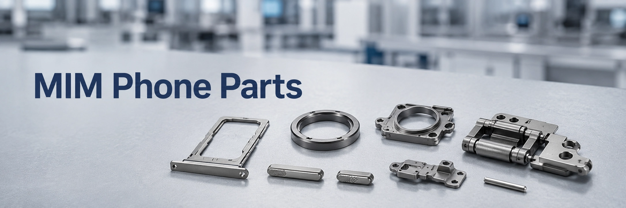
MIM is most relevant for small, complex, high-volume phone metal components rather than generic consumer accessories or simple flat metal parts.
MIM mobile phone parts are small, high-density metal components used in smartphone assemblies when compact geometry, thin walls, cosmetic surfaces, repeated mechanical contact, or high-volume production makes CNC machining, stamping, die casting, or plastic injection molding less suitable. This page focuses on custom MIM phone components, not phone repair parts or consumer accessories. It helps product engineers and technical sourcing teams decide whether parts such as SIM trays, camera frames, lens rings, buttons, selected foldable hinge components, connector hardware, internal brackets, pins, or miniature mechanism parts should enter a MIM DFM review. Continue reading if your drawing includes small holes, slots, undercuts, visible surfaces, hinge or button contact features, material and finishing requirements, or annual volume large enough to justify MIM tooling.
Direct answer: MIM is suitable for selected smartphone metal components such as SIM trays, camera frames, lens rings, side buttons, foldable hinge elements, connector interface hardware and compact brackets when the design combines small size, complex 3D features, metal performance, surface requirements and repeat production volume. Simple flat shields, low-volume prototypes and large frame-like parts should usually be compared with stamping, CNC machining, die casting or plastic injection molding before choosing MIM.
Quick Engineering Summary for MIM Phone Components
Use MIM When
The part combines compact 3D geometry, production volume, metal performance, and features that would be expensive to machine or assemble repeatedly.
Prüfung vor dem Werkzeugbau
Wall thickness, gate position, cosmetic surfaces, shrinkage compensation, datum strategy, secondary machining areas, surface finishing, and inspection requirements should be checked before mold design.
Do Not Force MIM
Simple flat shields, low-volume prototypes, large external frames, or parts requiring tight machining on nearly every surface may be better suited to another process.
Which Mobile Phone Parts Are Suitable for MIM?
MIM is most useful when a mobile phone component combines small size, complex geometry, metal performance, and repeatable production volume. The Metal Injection Molding Association explains MIM suitability through shape complexity, material performance, production quantity, and component cost. In phone projects, this means the process decision should start from the drawing, not from the part name alone.
Geeignete Kandidaten
- Small metal geometry with multiple features
- Holes, slots, side features, undercuts, ribs, bosses, or local steps
- Production volume that can justify tooling and first-article correction
- Stainless steel, low alloy steel, or specialty alloy requirements
- Cosmetic surfaces that need stable shape before finishing
- Repeated functional contact, such as button, hinge, latch, or sliding areas
Usually Better for Another Process
- Simple sheet-metal shields or flat spring parts
- Large thin frames or long external housing structures
- Very low-volume prototypes or still-changing designs
- Parts requiring extensive post-machining across most surfaces
- Non-metal parts where plastic injection molding is sufficient
Core Review Questions
- Does the part include complex 3D features?
- Is the expected production volume high enough for tooling?
- Does the part require metal strength, hardness, wear resistance, corrosion resistance, or surface stability?
- Are critical dimensions realistic for MIM, or do selected areas need machining?
Technischer Hinweis: The strongest MIM candidates are not simply small parts. They are small parts where fine powder feedstock injection, debinding, sintering shrinkage compensation, and near-net-shape forming can reduce repeated machining, part consolidation, or geometry-related manufacturing risk.
Common MIM Mobile Phone Parts by Assembly Area
Smartphone MIM applications should be reviewed by assembly area, not only by part name. The same part family can have different risks depending on whether it is used as a cosmetic part, internal structural feature, hinge element, connector interface, or alignment component. PIM International has reported smartphone MIM examples including SIM card trays, camera lens protection rings and covers, volume and power side buttons, I/O port connector interface parts, micro gear reducers, and folding smartphone hinge-related components.

This figure helps users identify possible phone assembly areas for MIM review, including tray-like parts, camera rings, brackets, button-like parts and hinge-related elements. The engineering decision still depends on drawing geometry, material, tolerance and volume.
SIM Card Trays and Ejector Mechanism Parts
SIM card trays are common smartphone MIM candidates when the design requires a thin metal frame, clean external appearance, stable fit, and repeated insertion or removal. The engineering challenge is not only forming the tray shape. The real risk is maintaining flatness, wall consistency, edge quality, cosmetic surface finish, and slot fit after sintering and finishing.
For a SIM tray, engineers should review tray wall thickness, card slot fit, ejector contact area, cosmetic surface orientation, sintering warpage risk, and whether polishing, coating, PVD, or plating will affect fit. If the design is a very simple flat tray with minimal 3D features, stamping or CNC machining may be more practical.
Phone Camera Frames, Lens Rings and Camera Module Brackets
Camera frames, lens rings, and camera module brackets can be suitable for MIM when the part is small, metal, feature-dense, and sensitive to cosmetic or assembly requirements. These parts often combine visible surfaces, thin ring-like geometry, mounting points, local shoulders, and datum surfaces.
Important review points include gate mark location, polishing or coating impact, ring or frame distortion during sintering, module alignment datums, and whether screw holes, slots, or locating features need secondary machining. Camera-related phone parts may look cosmetic, but they can also influence assembly alignment, local stiffness, drop performance, and surface durability. For tolerance-sensitive designs, review related guidance on hochpräzise MIM-Teile.
Side Buttons, Power Buttons and Volume Buttons
Side buttons are small, visible, and frequently touched components. They may be suitable for MIM when the design needs metal feel, consistent geometry, controlled surface finishing, or small functional features that interact with internal switch mechanisms.
In production, the risk is often the relationship between surface finishing and functional fit. A polished or coated button may pass visual review but create dimensional variation at the mating feature. Engineers should check tactile feel, contact wear, surface consistency, edge condition, and fit with internal plastic or metal mating parts.
Foldable Phone Hinge Components
Foldable phone hinge assemblies can include selected MIM parts, but MIM should not be described as the process for the entire hinge module. MIM is more relevant for small hinge components such as links, pivots, brackets, cam-like features, sliding interfaces, locking elements, and compact parts with holes or contact surfaces.
Important review points include hole position, pivot alignment, friction or wear surfaces, local hardness, strength requirements, distortion risk after sintering, secondary machining, and surface treatment compatibility. For broader hinge structure intent, review MIM precision hinge parts and related verschleißfeste MIM-Teile.
I/O Connector Interface and Small Connector Hardware
Some mobile phone connector interface parts may use MIM when they require compact metal geometry, local support features, high repeatability, or structural reinforcement around a charging or I/O interface. This section should not be confused with electronic connector manufacturing, which may involve stamping, plating, plastic molding, and electrical contact design.
For MIM review, the focus should be on the small metal housing, locating feature, support frame, or interface hardware. Key concerns include thin wall sections, local stiffness, fit with plastic or stamped connector parts, plating compatibility, burr-sensitive areas, and dimensional consistency at assembly features.
Internal Brackets, Locating Parts and Support Features
Internal phone brackets and locating features are suitable for MIM when they combine multiple functions in one small metal component. Examples include compact mounting brackets, locating blocks, small support frames, sensor brackets, or reinforcement parts used in crowded internal layouts.
The engineering value of MIM is strongest when it can consolidate several features, such as screw bosses, locating shoulders, support ribs, alignment faces, cable clearances, and local structural reinforcement. Broader structure-family intent should be directed to MIM-Halterungsteile.
Miniature Mechanism Parts, Gears, Pins and Small Motion Components
Some smartphone mechanisms may include miniature gears, shafts, pins, sliding parts, or small motion components. MIM may be considered when the part is compact, complex, and needed in production volume. These should be reviewed based on load, wear, surface finish, mating material, and dimensional control.
For structure-specific guidance, review MIM-Zahnradteile und MIM-Wellen und -Stifte.
MIM Suitability Matrix for Smartphone Components
The table below provides a practical first-screen review. It does not replace a drawing-based DFM review, but it helps engineers and sourcing teams decide whether a phone component is worth sending for MIM evaluation.

A phone component should be reviewed for MIM based on geometry, volume, material and tolerance. Strong candidates usually combine compact 3D features with production volume; simple flat parts often belong to another process.
| Mobile Phone Part Type | MIM-geeignet | Why It May Fit MIM | Main Review Points | Alternative Process to Compare |
|---|---|---|---|---|
| SIM card tray | Strong / Drawing-Dependent | Thin metal frame, high-volume production, cosmetic surfaces | Flatness, slot fit, deformation, coating thickness | Stamping, CNC machining, die casting |
| Camera frame / lens ring | Strong / Drawing-Dependent | Small metal frame, cosmetic and assembly features | Datum, visible surface, polishing, coating, distortion | CNC machining, die casting, stamping |
| Seitendrücker | Bedingt | Small cosmetic metal part with repeated contact | Tactile feel, wear, surface finish, fit | CNC machining, stamping |
| Foldable hinge component | Strong Candidate | Complex geometry, holes, pivot or contact features | Alignment, wear, secondary machining, distortion | CNC machining, stamping plus assembly |
| Connector interface hardware | Bedingt | Compact metal support or interface structure | Plating, fit, thin sections, mating parts | Stamping, CNC machining |
| Internal bracket / locating part | Bedingt | Multi-feature structural or locating component | Hole position, datum strategy, rib layout | Stamping, die casting, CNC machining |
| Miniature mechanism part | Bedingt | Compact motion feature or gear-like geometry | Wear, tooth/contact geometry, material hardness | Micro machining, powder metallurgy, stamping |
| Simple flat plate or shield | Weak | Not enough geometry complexity | Cost, burrs, volume | Stanzen |
The strongest candidates usually combine several requirements at the same time: compact 3D geometry, material performance, production volume, and reduced dependence on secondary machining. If the part is simple and flat, MIM may create unnecessary tooling and process cost.
Material Direction for MIM Mobile Phone Parts
Material choice for mobile phone MIM parts should be driven by function, surface requirement, contact condition, and assembly environment. This section gives initial direction only. Final material selection should be confirmed through project-specific DFM, material review, heat treatment review, surface finishing review and inspection planning.

Material selection should be reviewed together with appearance, contact condition, strength, wear, corrosion exposure and the final finishing route. A material that forms well may still be unsuitable if finishing or contact requirements are ignored.
| Phone Part Type | Übliche Werkstoffrichtung | Why It May Be Considered | Caution Before Selection |
|---|---|---|---|
| SIM card tray | 316L stainless steel or selected stainless steel direction | Corrosion resistance, appearance, hand-contact exposure and stable finishing route | Flatness, polishing, coating thickness and tray slot fit must be reviewed together. |
| Camera frame / lens ring | 316L, 17-4 PH or project-specific stainless steel direction | Cosmetic surface, local stiffness, alignment features and finishing compatibility | Ring distortion, datum control, visible surface quality and coating impact are critical. |
| Seitendrücker | 316L, 17-4 PH, 420 or other stainless steel direction depending on wear and strength | Metal feel, repeated touch, contact surface and visible finish requirement | Surface treatment may change tactile feel, contact dimension and edge quality. |
| Foldable hinge component | 17-4 PH, 420, 440C or selected strength / wear-oriented material direction | Pivot, sliding, contact or load-bearing areas may need strength and wear resistance | Heat treatment, hardness, secondary machining and mating material must be reviewed at assembly level. |
| Internal bracket / connector hardware | 316L, 17-4 PH, low alloy steel or specialty alloy direction | Structural support, locating features, fit and possible plating or finishing needs | Material should be confirmed by function, surface treatment, tolerance and mating part requirements. |
| Werkstoffrichtung | Typical Phone-Part Reason | Review Notes |
|---|---|---|
| 316L-Edelstahl | Clean appearance, corrosion resistance, hand-contact exposure | Useful for visible parts or corrosion-sensitive surfaces, but not ideal when high hardness is the primary requirement. |
| 17-4 PH Edelstahl | Higher strength or structural support | Heat treatment response, dimensional stability and inspection requirements should be reviewed together. |
| 420 / 440C Edelstahl | Hardness and wear areas | Suitable for selected contact or motion features, but finishing and corrosion behavior must be checked. |
| Low alloy steel or special alloys | Cost, strength, magnetic behavior or special functional needs | Should be selected based on actual assembly function, not keyword assumptions. |
For broader material comparison, review MIM-Werkstoffen, Edelstahl-MIM-Werkstoffe, und der MIM-Materialauswahl-Leitfaden. If several material families are being considered, the MIM materials comparison page can support early screening.
DFM Risks in Mobile Phone MIM Parts
DFM review is essential for mobile phone MIM parts because many phone components are small, feature-dense, cosmetic, and assembly-sensitive. The MIM process involves fine metal powder and binder feedstock, injection molding, green part handling, debinding, and sintering. The MIMA-Prozessübersicht describes feedstock preparation, molding, binder removal and sintering as core MIM stages, with part shrinkage and densification occurring during the thermal stage.

Phone MIM parts should be reviewed for thin walls, gate marks, critical datums and finishing surfaces before tooling. These issues affect mold design, sintering distortion, secondary machining and final inspection.
Thin Walls and Local Section Transitions
Thin walls are common in phone trays, frames, and brackets. Local wall variation can affect molding flow, cooling, debinding, and sintering behavior. Engineers should review minimum wall thickness, sudden thick-to-thin transitions, ribs, bosses, short-shot risk and distortion risk.
Small Holes, Slots, Undercuts and Side Features
MIM can form complex features, but every side hole, slot, groove or undercut still needs moldability and sintering review. If a hole controls a hinge pivot, camera datum or connector position, secondary machining or tighter inspection may be needed.
Cosmetic Surfaces and Gate Location
Many phone components have visible surfaces. Gate placement must be reviewed before tooling because a gate mark, flow mark, weld line, or local surface disturbance can become unacceptable after polishing, coating, PVD, or plating.
Sinterschwindung und Verzug
MIM parts shrink during sintering, and tooling must compensate for this shrinkage. For phone parts, this affects camera frame flatness, SIM tray straightness, button fit, bracket hole position and hinge component alignment.
Critical Datums and Secondary Machining
Not every surface should carry tight tolerance. The drawing should identify datum faces, holes, slot widths, pivot centers, locating shoulders and mating surfaces that truly control assembly.
Surface Finishing and Plating Risks
Polishing, coating, plating, PVD, passivation or other finishing steps can influence final thickness, edge quality, surface feel and assembly fit. The finishing route should be reviewed together with material and tolerance strategy.
Vor dem Werkzeugbau: mark cosmetic surfaces, gate-sensitive areas, functional datums, post-machined features and inspection-critical dimensions on the drawing. This avoids treating every surface as equally critical and helps control tooling cost, first-article correction and final inspection effort.
Critical Drawing Features and Inspection Focus
For mobile phone MIM parts, tolerance review should separate functional control features from general as-sintered geometry. Final tolerances depend on drawing requirements, material direction, feature size, tooling compensation, sintering support, secondary operations, surface finishing and inspection method.
| Zeichnungsmerkmal | Warum das wichtig ist | Review Method | Typical Risk if Undefined |
|---|---|---|---|
| Functional datum faces | Control camera module location, hinge alignment, connector fit or tray insertion direction | Drawing datum review, CMM or fixture-based dimensional inspection where specified | Visible appearance may pass while assembly position fails. |
| Small holes and pivot centers | Affect hinge motion, pin fit, screw alignment or mechanism repeatability | Pin gauge, optical measurement, CMM or secondary machining review | Hole shift, ovality or post-sintering distortion can create assembly friction or misalignment. |
| Thin walls, slots and tray openings | Influence molding flow, debinding stability, sintering deformation and final fit | Wall thickness review, slot width inspection, visual and functional fit check | Warpage, slot interference, short shot or edge deformation may appear after sintering or finishing. |
| Cosmetic and visible surfaces | Determine whether gate marks, flow marks, polishing direction or coating defects are acceptable | Surface inspection, finishing route review and appearance boundary definition | Gate or finishing decisions may conflict with the visible side of the product. |
| Post-machined or high-precision areas | Clarify which features cannot rely only on as-sintered accuracy | Secondary machining review, tolerance stack-up review and final inspection plan | Cost increases if too many surfaces are later treated as precision machining requirements. |
| Coating, plating or PVD-sensitive dimensions | Final thickness and surface condition can change mating fit or tactile feel | Finish specification review, thickness allowance and final functional check | Parts may pass before finishing but fail after coating or polishing. |
When MIM Is Not the Best Process for Phone Parts
MIM is a strong manufacturing option for selected mobile phone components, but it is not always the best process. EPMA describes MIM as a process for complex shape parts in high quantities, while also noting that if a shape can be produced economically by conventional pressing and sintering, MIM would often be too expensive. The same decision logic applies when comparing MIM with CNC machining, stamping, die casting or plastic injection molding for phone components.
| Verfahren | Usually Better For | MIM Should Be Considered When |
|---|---|---|
| CNC-Bearbeitung | Prototypes, low-volume parts, very tight local machined surfaces | The geometry is stable, production volume is high, and repeated machining becomes costly. |
| Stanzen | Simple thin plates, springs, shields, flat clips | The design becomes compact, 3D, feature-dense or difficult to form consistently. |
| Druckguss | Larger frame-like metal parts or housing structures | The component is smaller, more precise and has complex details better suited to MIM tooling. |
| Kunststoffspritzguss | Non-metal cosmetic or insulation parts | Metal strength, wear resistance, stiffness, conductivity or temperature resistance is required. |
| Mehrteilige Baugruppe | Simple mechanisms assembled from several low-cost parts | MIM can consolidate several functions into one compact metal component. |
If nearly every surface requires tight machining after sintering, the near-net-shape value of MIM is reduced. MIM may still be useful if it forms a complex base shape, but the cost model must include secondary machining, inspection and tolerance risk.
Verbundene Fallszenarien für die technische Schulung
The following scenarios are composite field scenarios for engineering training. They do not represent a named customer, confirmed order, disclosed project, inspection result or proprietary design.
| Szenario | Problem | Likely System Cause | Prevention Before Tooling |
|---|---|---|---|
| SIM tray warpage after cosmetic finishing | A thin SIM tray concept looked acceptable in CAD, but had a high risk of poor flatness after sintering and finishing. | Uneven wall sections, sharp local transitions and finishing allowance were not reviewed together. | Separate cosmetic surfaces, fit surfaces and non-critical edges on the drawing before mold design. |
| Camera frame assembly misalignment | The outer shape appeared correct, but camera module location risk remained unclear. | Cosmetic surface requirements and assembly control features were not separated in the tolerance strategy. | Define functional datums, locating features and general as-sintered areas before tooling review. |
| Foldable hinge component wear concern | A small hinge component fit MIM geometry, but the contact surface raised wear and cycle-life concerns. | The part was reviewed as a single geometry instead of a hinge-system component with mating materials and repeated contact. | Review wear surfaces, pivot holes, mating materials, heat treatment, finish and lifetime test requirements together. |
When a Phone Component Needs a Deeper Engineering Review
The Mobile Phone Parts page should remain a device-level application page. Some phone component categories may deserve deeper engineering review when the drawing, application risk and search demand justify a separate page. Until those deeper pages are published, this section should guide users by review topic rather than exposing internal URL planning.
| Deeper Review Topic | When It Deserves Separate Review | Current Page Boundary |
|---|---|---|
| Foldable phone hinge components | The part involves pivots, sliding contact, holes, friction surfaces, local hardness, secondary machining or lifetime-cycle requirements. | This page introduces phone hinge use cases; detailed hinge structure, wear and motion review should connect to MIM precision hinge parts und verschleißfeste MIM-Teile. |
| Phone camera frames and lens rings | The part includes visible surfaces, ring-like geometry, module alignment, polishing, coating, datum control or distortion risk. | This page explains camera-area suitability; deeper pages should focus on camera frame DFM, cosmetic surfaces and alignment control. |
| Custom MIM SIM card trays | The tray requires metal strength, high-volume production, slot fit, edge quality, cosmetic finish and deformation control. | This page avoids consumer replacement-tray intent; any deeper page should stay focused on custom MIM manufacturing and DFM review. |
| Phone button and connector hardware | The design includes tactile feel, repeated contact, plating, fit with mating parts, or compact metal support features. | These topics can remain in this L3 page unless future search data or project inquiries justify separate engineering pages. |
What to Provide for a Mobile Phone MIM Parts Review
A drawing-based review is the most useful next step when a phone component appears suitable for MIM. The engineering team needs enough information to evaluate manufacturability, tooling risk, material direction, finishing requirements, tolerance strategy and production feasibility.

A useful MIM quotation starts with engineering inputs, not only a part name or target price. Drawings, CAD data, material direction, tolerance notes and volume assumptions allow the project team to review tooling risk before production planning.
RFQ and DFM Review Checklist
- 2D-Zeichnung mit Maßen und Toleranzen
- 3D-CAD-Datei
- Material requirement or target material family
- Cosmetic surface indication
- Critical assembly features and datums
- Surface finish, coating, plating, PVD or passivation requirement
- Erwartete Jahresstückzahl
- Prototyp- oder Serienstadium
- Informationen zum Gegenstück
- Load, wear or repeated-use condition
- Inspection or acceptance requirements
- Target application area inside the phone assembly
Was XTMIM vor dem Werkzeugbau prüft
- Whether the component is suitable for MIM
- Whether CNC, stamping, die casting or plastic injection molding should be compared
- Whether the geometry creates molding, debinding or sintering risks
- Whether the material direction is realistic
- Whether critical tolerances need secondary machining
- Whether cosmetic surfaces conflict with gate location
- Whether finishing may affect final dimensions
- Whether production volume supports MIM tooling
Inspection and Acceptance Points
- Critical dimensions and datum features
- Flatness, straightness or alignment requirements
- Hole position, slot width and mating features
- Visible surface quality and finishing consistency
- Contact or wear surfaces after treatment
- Post-machined features versus as-sintered features
- Material and heat treatment confirmation where required
- Functional fit with mating phone assembly parts
Request a Mobile Phone MIM Part Review
If your mobile phone component includes compact metal geometry, cosmetic surfaces, hinge or button contact features, camera module alignment requirements, or high-volume production needs, send your drawings for a MIM feasibility review. Please provide 2D drawings, 3D CAD files, target material, tolerance requirements, cosmetic surface notes, surface finish or coating requirements, estimated annual volume, assembly position and any testing or inspection requirements.
XTMIM can review whether the part is suitable for MIM, whether another process should be compared, which features create tooling or sintering risk, whether secondary machining may be needed, and which material direction should be evaluated before tooling, trial production or volume production planning.
FAQ About MIM Mobile Phone Parts
What mobile phone parts are commonly made by MIM?
Common MIM mobile phone parts may include SIM card trays, camera frames, lens rings, side buttons, selected foldable hinge components, connector interface hardware, internal brackets, pins, and miniature mechanism parts. The final process choice depends on geometry, material, tolerance, surface finish, and production volume.
Is MIM suitable for foldable phone hinge parts?
MIM can be suitable for selected small components inside a foldable phone hinge, such as links, pivots, brackets, cam-like features, or contact elements. It should not be assumed that the entire hinge module is made by MIM. Torque, wear, alignment, and lifetime requirements must be reviewed at the assembly level.
What makes a foldable phone hinge component suitable for MIM?
A foldable phone hinge component may suit MIM when it is small, metal, complex, and includes holes, pivots, sliding surfaces, locking features, local contact areas or geometry that would be difficult to machine or assemble repeatedly. Wear surfaces, mating materials, heat treatment, surface finish and inspection requirements should be reviewed before tooling.
Which materials are used for MIM phone components?
Common directions include 316L stainless steel for corrosion resistance and appearance, 17-4 PH stainless steel for higher strength, 420 or 440C stainless steel for hardness and wear areas, and selected low alloy or specialty alloys for functional requirements. Final selection should be confirmed by drawing, application, surface finish, and inspection requirements.
Is MIM better than stamping for SIM card trays?
MIM may be better than stamping for a SIM card tray when the tray has compact 3D geometry, metal thickness transitions, cosmetic surfaces, high-volume production needs, or features that are difficult to form consistently. Stamping may be more practical for simple flat tray designs with limited 3D detail and lower geometry complexity.
Are all phone camera rings suitable for MIM?
No. A phone camera ring is suitable for MIM only when its size, geometry, material, surface finish, alignment requirements and production volume support the MIM route. Simple rings may be better produced by CNC machining, stamping or die casting, while complex rings with multiple features and stable volume may justify MIM review.
Can MIM replace CNC machining for smartphone parts?
MIM can replace CNC machining when the part is small, complex, needed in production volume, and does not require heavy machining on most surfaces. CNC is often more practical for prototypes, low-volume parts, or components requiring very tight machined surfaces across most of the geometry.
Can MIM be used for cosmetic phone parts?
Yes, selected cosmetic phone parts may be reviewed for MIM, but gate location, material, polishing, coating, plating, edge quality, and dimensional changes after finishing must be considered before tooling. Cosmetic requirements should be clearly marked on the drawing.
What information is needed for a mobile phone MIM parts quotation?
A useful quotation package should include 2D drawings, 3D CAD files, material requirements, tolerances, cosmetic surface areas, surface finish requirements, estimated annual volume, application background, mating part information, and inspection requirements.
When should a phone part not be made by MIM?
MIM may not be the best choice for simple flat stamped parts, low-volume prototypes, large external frames, plastic functional parts, or designs requiring tight machining across nearly all surfaces. These parts should be compared with stamping, CNC machining, die casting, plastic injection molding, or another process.
Technische Prüfung und Referenzen
Normenhinweis: Material properties, tolerances, inspection methods and acceptance criteria should be confirmed against the customer drawing, project specification, purchase order, material datasheet and applicable formal standards. For MIM materials and properties, sources such as MPIF Standard 35-MIM may be relevant when specified by the project, but specific values should not be assumed without the current standard document and project requirements.
- MIMA – Konstruieren mit MIM: used as a technical reference for MIM suitability based on shape complexity, material performance, production quantity and component cost.
- MIMA – Prozessübersicht: MIM: used as a technical reference for feedstock preparation, molding, binder removal, sintering, shrinkage and secondary operations.
- EPMA – Metal Injection Moulding: used as a reference for MIM suitability for complex shape parts in high quantities and for shrinkage-control considerations.
- PIM International – Smartphone MIM applications: used as an industry reference for smartphone MIM component examples such as SIM trays, camera lens rings, side buttons, connector interface parts and folding smartphone hinge-related parts.