
This page shows custom MIM metal parts used in mobile phone assemblies, not replacement phone accessories or retail spare parts. XTMIM manufactures custom MIM mobile phone components from drawings, including SIM card trays, camera lens rings, camera frames, side buttons, selected foldable-phone hinge components, connector interface support hardware and compact internal brackets. The page is positioned as a real mobile phone MIM parts display page first, supported by concise engineering review content. It does not present large phone housings or simple flat shields as the main MIM opportunity.
The examples below help product engineers, sourcing teams and project managers compare their own smartphone components with real MIM candidate families before sending drawings for a feasibility review. The strongest candidates usually combine small size, complex 3D geometry, thin walls, holes, slots, ribs, tabs, cosmetic surfaces, contact areas or repeat production requirements.
Direct answer: The most suitable mobile phone MIM parts are small metal components that need compact geometry, repeatable dimensions and controlled surface quality. Typical examples include SIM card trays, camera lens rings, camera frames, side buttons, selected foldable hinge links, connector support hardware and internal brackets. Final suitability depends on the drawing, wall thickness, tolerance notes, material, finish, assembly position and annual volume.
Typical Mobile Phone MIM Part Geometry Features
This is the main part-display section for the page. It uses real mobile phone metal component images to show both the part families and the geometry features that make these components relevant to MIM: thin-wall trays, camera ring openings, side-button contact faces, compact hinge links, connector support structures, internal brackets, small holes, tabs, ribs, bosses and locating details.

Thin-Wall Tray Frames
SIM tray parts usually need thin-wall metal frames, clean external edges, stable card slot dimensions and finish control after coating or PVD.

Ring Openings and Module Datums
Camera lens rings and frames often combine circular openings, stepped surfaces, small locating areas and visible finishes.

External Button Surfaces
Side buttons and power buttons are small external components where hand feel, edge radius, surface finish and mating clearance matter.
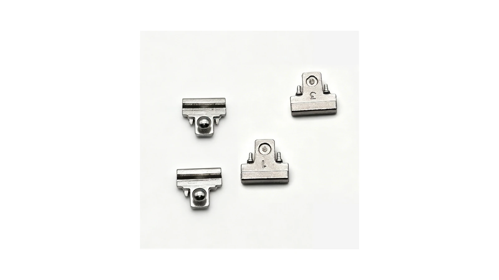
Pivot, Link and Locking Features
MIM may fit selected links, pivot supports, locking pieces or sliding-contact parts, while full hinge-module function must still be reviewed at assembly level.
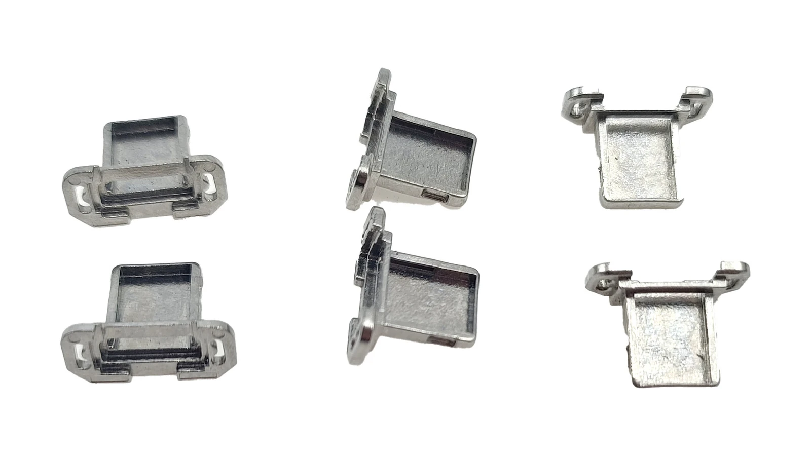
Compact Interface Hardware
Charging-port and I/O area support parts may require local reinforcement, small holes, tabs, locating faces or finish compatibility.
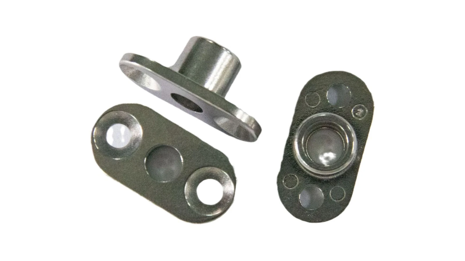
Holes, Bosses, Ribs and Datums
Internal brackets are good MIM candidates when the design consolidates mounting holes, ribs, bosses, tabs and locating datums into a small metal part.
Display boundary: This page uses phone assembly context as the main theme. Detailed design rules for general hinges, brackets, shafts, pins, gears or high-precision parts should remain on their own structure-family pages, while this page shows how those part families appear inside mobile phone assemblies.
MIM Suitability Matrix for Smartphone Components
This condensed matrix keeps the useful engineering judgment from the old support section while avoiding the previous generic diagram image. It helps engineers decide whether a phone component is worth sending for MIM evaluation after they compare it with the real part examples above.
| Mobile Phone Part Type | MIM Fit | Why It May Fit MIM | Main Review Points | Alternative Process to Compare |
|---|---|---|---|---|
| SIM card tray | Strong / Drawing-dependent | Thin metal frame, repeat production and cosmetic surfaces | Flatness, slot fit, deformation, coating thickness | Stamping, CNC machining, die casting |
| Camera frame / lens ring | Strong / Drawing-dependent | Small metal frame with cosmetic and assembly features | Datum, visible surface, polishing, coating, distortion | CNC machining, die casting, stamping |
| Side button | Conditional | Small cosmetic metal part with repeated contact | Tactile feel, wear, surface finish, fit | CNC machining, stamping |
| Foldable hinge component | Strong candidate | Complex geometry, holes, pivot or contact features | Alignment, wear, secondary machining, distortion | CNC machining, stamping plus assembly |
| Connector support hardware | Conditional | Compact metal support or interface structure | Plating, fit, thin sections, mating parts | Stamping, CNC machining |
| Internal bracket / locating part | Conditional | Multi-feature structural or locating component | Hole position, datum strategy, rib layout | Stamping, die casting, CNC machining |
| Simple flat plate or shield | Weak | Not enough geometry complexity | Cost, burrs, volume | Stamping |
DFM and Inspection Review for Phone MIM Parts
DFM content should support the part display, not replace it. For smartphone MIM parts, the most important review points are thin walls, local section transitions, small holes, slots, visible surfaces, gate location, sintering shrinkage, finishing allowance and inspection datums.
Thin Walls and Section Transitions
Thin walls are common in trays, frames and brackets. Sudden thick-to-thin changes can affect flow, debinding behavior, sintering distortion and final flatness.
Small Holes, Slots and Undercuts
Pivot holes, tray slots, locating holes and compact undercuts need moldability, sintering and inspection review before tooling.
Cosmetic Surfaces and Gate Location
Visible phone surfaces make gate placement important because gate marks or flow disturbances can become unacceptable after polishing, coating, plating or PVD.
Sintering Shrinkage and Distortion
Tooling compensation and support planning affect SIM tray flatness, camera ring roundness, button fit and hinge component alignment.
Functional Datums
Drawings should identify the faces, holes, slot widths, pivot centers and locating shoulders that actually control phone assembly fit.
Finishing and Coating Allowance
Polishing, coating, plating, PVD and passivation can influence final thickness, edge quality, surface feel and mating fit.
| Drawing Feature | Why It Matters | Review Method | Typical Risk if Undefined |
|---|---|---|---|
| Functional datum faces | Control camera module location, hinge alignment, connector fit or tray insertion direction | Drawing datum review, CMM or fixture-based dimensional inspection where specified | Visible appearance may pass while assembly position fails. |
| Small holes and pivot centers | Affect hinge motion, pin fit, screw alignment or mechanism repeatability | Pin gauge, optical measurement, CMM or secondary machining review | Hole shift, ovality or post-sintering distortion can create friction or misalignment. |
| Thin walls, slots and tray openings | Influence molding flow, debinding stability, sintering deformation and final fit | Wall thickness review, slot width inspection, visual and functional fit check | Warpage, slot interference, short shot or edge deformation may appear after sintering or finishing. |
| Cosmetic and visible surfaces | Determine whether gate marks, polishing direction or coating defects are acceptable | Surface inspection, finishing route review and appearance boundary definition | Gate or finishing decisions may conflict with the visible side of the product. |
| Coating, plating or PVD-sensitive dimensions | Final thickness and surface condition can change mating fit or tactile feel | Finish specification review, thickness allowance and final functional check | Parts may pass before finishing but fail after coating or polishing. |
Material and Finish Options by Mobile Phone Part Type
Material and surface treatment should support the specific phone component instead of becoming a separate material-selection topic. For most phone MIM projects, the practical question is whether the chosen material and finish can support part location, cosmetic surface, mating fit, wear condition and production volume.
| Phone MIM Part Type | Typical Material Direction | Surface / Finish Direction | Main Review Point |
|---|---|---|---|
| SIM card tray | 316L stainless steel or selected stainless steel direction | Polishing, PVD, coating, passivation or cosmetic finish | Thin-wall frame stability, slot fit, coating thickness and insertion behavior. |
| Camera lens ring / camera frame | 316L, 17-4 PH or project-specific stainless steel direction | Polishing, PVD, bead blasting, coating or appearance-focused finish | Visible surface, ring distortion, datum control and module assembly fit. |
| Side button / power button | 316L, 17-4 PH, 420 or other stainless steel direction | Polishing, coating, PVD or tactile surface finishing | Hand feel, edge quality, mating clearance and finish consistency. |
| Foldable hinge component | 17-4 PH, 420, 440C or wear-oriented alloy direction | Heat treatment, grinding, coating or functional contact finish | Hole position, pivot fit, wear surface, hardness and secondary machining allowance. |
| Connector support / internal bracket | 316L, 17-4 PH, low alloy steel or specialty alloy direction | Passivation, plating, functional finish or assembly-specific treatment | Locating datum, boss strength, mounting fit, corrosion exposure and finish compatibility. |
For deeper material decisions, review MIM materials, stainless steel MIM materials and the MIM material selection guide. This page keeps material discussion tied to mobile phone part examples.
When MIM Is Not the Best Process for Phone Parts
MIM is a strong option for selected smartphone metal components, but it is not the correct route for every phone part. Simple flat parts, unstable prototype designs, large frame-like structures and parts requiring tight machining on nearly every surface should be compared with other processes before MIM tooling is considered.
| Process | Usually Better For | MIM Should Be Considered When |
|---|---|---|
| CNC machining | Prototypes, low-volume parts, very tight local machined surfaces | The geometry is stable, volume is high, and repeated machining becomes costly. |
| Stamping | Simple thin plates, springs, shields and flat clips | The design becomes compact, 3D, feature-dense or difficult to form consistently. |
| Die casting | Larger frame-like metal parts or housing structures | The component is smaller, more precise and has complex details better suited to MIM tooling. |
| Plastic injection molding | Non-metal cosmetic or insulation parts | Metal strength, wear resistance, stiffness, conductivity or temperature resistance is required. |
| Multi-part assembly | Simple mechanisms assembled from several low-cost parts | MIM can consolidate several functions into one compact metal component. |
Drawing Information Needed for Custom Mobile Phone MIM Parts
XTMIM manufactures custom phone MIM parts from drawings rather than selling fixed replacement phone accessories. A useful inquiry should show part geometry, application position, target material, tolerance requirements, cosmetic surfaces, mating features, production volume and expected surface treatment.
Part and Assembly Context
- 2D drawing with tolerance notes
- 3D CAD file when available
- Phone assembly position
- Mating parts and critical contact surfaces
- Visible cosmetic areas and hidden functional areas
Material and Finish Requirements
- Target material or performance requirement
- Surface finish, PVD, plating or coating expectation
- Wear, corrosion or hand-contact conditions
- Hardness or heat treatment direction if relevant
- Secondary machining areas if required
Production and Inspection Inputs
- Estimated annual volume
- Critical-to-function dimensions
- Flatness, roundness or hole-position notes
- Datum strategy for inspection
- Acceptance or assembly test requirements
FAQ About MIM Mobile Phone Parts
What mobile phone parts are commonly made by MIM?
Common mobile phone MIM parts may include SIM card trays, camera frames, lens rings, side buttons, selected foldable hinge components, connector support hardware, internal brackets, pins and miniature mechanism parts. The final process choice depends on geometry, material, tolerance, surface finish and production volume.
Is MIM suitable for foldable phone hinge parts?
MIM can be suitable for selected small components inside a foldable phone hinge, such as links, pivots, brackets, locking elements or contact parts. The entire hinge module should not be assumed to be MIM; torque, wear, alignment and lifetime requirements must be reviewed at assembly level.
Is MIM better than stamping for SIM card trays?
MIM may be better than stamping when a SIM tray has compact 3D geometry, metal thickness transitions, cosmetic surfaces, high-volume production needs or features that are difficult to form consistently. Simple flat tray designs may still be better suited to stamping.
Are all phone camera rings suitable for MIM?
No. A phone camera ring is suitable for MIM only when its size, geometry, material, surface finish, alignment requirements and production volume support the MIM route. Simple rings may be better produced by CNC machining, stamping or die casting.
Can MIM be used for cosmetic phone parts?
Yes, selected cosmetic phone parts may be reviewed for MIM, but gate location, material, polishing, coating, plating, PVD, edge quality and dimensional changes after finishing must be considered before tooling.
When should a phone part not be made by MIM?
MIM may not be the best choice for simple flat stamped parts, low-volume prototypes, large phone frames, plastic functional parts, or designs requiring tight machining across nearly all surfaces.
What information is needed for a mobile phone MIM parts quotation?
A useful quotation package should include 2D drawings, 3D CAD files, material requirements, tolerances, cosmetic surface areas, surface finish requirements, estimated annual volume, application background, mating part information and inspection requirements.
Engineering Review and Technical References
Standards note: Material properties, tolerances, inspection methods and acceptance criteria should be confirmed against the customer drawing, project specification, purchase order, material datasheet and applicable formal standards. Public MIM design and process references can support background review, but specific material values should not be assumed without current project requirements.
- MIMA – Designing with MIM: technical background for MIM suitability based on shape complexity, material performance, production quantity and component cost.
- MIMA – Process Overview: MIM: technical background for feedstock, molding, binder removal, sintering, shrinkage and secondary operations.
- EPMA – Metal Injection Moulding: reference for MIM suitability for complex shape parts in high quantities and shrinkage-control considerations.
- PIM International – Smartphone MIM applications: industry background for smartphone MIM component examples such as SIM trays, camera lens rings, side buttons, connector interface parts and folding smartphone hinge-related parts.
Submit a Mobile Phone MIM Part Drawing
If your smartphone component is a small metal part such as a SIM tray, camera lens ring, camera frame, side button, foldable hinge element, connector support or internal bracket, send the drawing for a MIM feasibility review.
Please provide 2D drawings, 3D CAD files, target material, tolerance requirements, cosmetic surface notes, surface finish or coating requirements, estimated annual volume and application background.