
MIM Manufacturing for Small and Miniaturized Metal Components
XTMIM manufactures small and miniaturized metal components using metal injection molding (MIM) when a part combines functional three-dimensional features, engineering-metal performance, and repeat production demand. The route is most relevant when holes, ribs, bosses, hooks, slots, contact details, or compact assembly interfaces would otherwise require repeated CNC operations or multi-piece assembly.
Before tooling, we review feature size, wall distribution, material and feedstock route, mold filling, debinding, sintering shrinkage, tolerance allocation, secondary operations, handling, and inspection access. MIM is not selected simply because a component is small; the design must be moldable, measurable, and stable enough for repeat production.
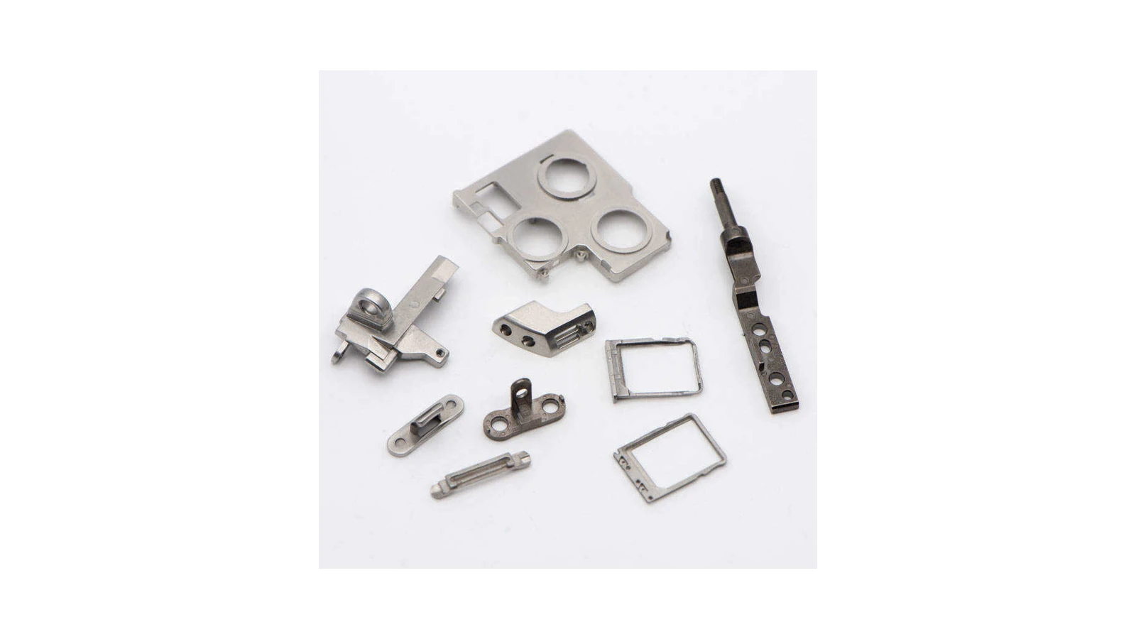
Where Small Metal Parts Become Difficult to Scale
A miniaturized component becomes a manufacturing problem when its functional detail is costly to reproduce, unstable through the full process chain, or difficult to inspect and handle consistently. The question is not only whether a small shape can be made, but whether it can be manufactured repeatedly without losing the interfaces that control fit, motion, contact, locking, sealing, or appearance.
Feature Density Drives Recurring Cost
Multiple small holes, slots, ribs, bosses, hooks, grooves, and local interfaces can create repeated CNC setups, delicate tooling, deburring, fixturing, and assembly work.
Prototype Detail Does Not Automatically Scale
A feature that works in a machined prototype may change during molding, debinding, handling, or sintering unless wall balance, tool strength, support, and tolerance allocation are reviewed before tooling.
Inspection and Handling Can Control the Route
Miniature parts may require defined datums, optical or fixture-based measurement, protected packaging, and selective finishing because very small features are easy to damage and difficult to verify.
Review a Representative Small Complex MIM Part
For a structured example covering feature-dense geometry, annual volume, recurring machining, tolerance split, shrinkage validation, tooling revision, and inspection planning, see the small complex MIM part review.
Check Whether a Miniaturized Metal Component Is a Good MIM Candidate
Small size alone does not make a part suitable for MIM. A stronger candidate combines useful three-dimensional detail, repeat demand, realistic tolerance allocation, metal-performance requirements, and a design that can be tooled, processed, handled, and inspected consistently.
Strong MIM Signals for Miniaturized Parts
MIM is usually worth reviewing when the part is small, feature-rich, mechanically functional, repeated in volume, and expensive or difficult to make by feature-by-feature machining.
Usually worth reviewing
Small metal part with holes, grooves, ribs, bosses, curved features, locking details, or miniature interfaces that are repeated in production.
Good production condition
The function is known, the material target is clear, and only selected dimensions require tight finishing or secondary operations.
Miniature Parts That Need DFM Redesign
Some small parts can work in MIM, but only after design changes. The common issues are extremely thin ribs, fragile pins, deep blind holes, sharp corners, small isolated bosses, and tolerance expectations copied directly from CNC drawings.
Feature strength risk
Very thin ribs, tiny posts, sharp fingers, or unsupported features may deform or break during molding, debinding, handling, or sintering.
Inspection risk
Miniature features may be difficult to inspect reliably unless datum logic, measurement method, and acceptance criteria are defined early.
Small Parts That May Not Belong in MIM
MIM is not always the best route for every tiny component. CNC micro machining, stamping, wire forming, photo etching, additive manufacturing, or assembly may still be better depending on geometry, volume, and tolerance requirements.
Usually poor fit
Very low-volume parts, extremely simple stamped profiles, long wire-like parts, ultra-thin sheet features, or parts with no real 3D complexity.
High conversion risk
Parts requiring ultra-tight tolerances across nearly all miniature features, fragile unsupported geometry, or inspection-limited internal details.
Information Needed for a Useful Small-Part Review
A practical review needs enough information to understand the part function and manufacturing pain point. A tiny feature may be acceptable if it is non-critical, but risky if it controls alignment, locking, sealing, electrical contact, or motion.
Send engineering data
2D drawing, 3D model, material grade, annual volume, critical dimensions, surface finish, assembly location, and current manufacturing route.
Send function context
Mating parts, locking areas, contact features, wear zones, cosmetic surfaces, handling requirements, post-processing needs, and known failure concerns.
Miniaturized Metal Components and Micro MIM Are Related but Not Identical
Both involve very small metal parts or features, but the engineering review starts from a different question. A miniaturized-component review asks whether the complete part can be manufactured repeatedly by MIM. A Micro MIM review becomes more important when feature scale itself creates the main tooling, filling, sintering, handling, or measurement risk.
Start With the Complete Component
Use a miniaturized-component review when the main question is whether the complete part is suitable for repeat MIM production. Review functional geometry, material direction, annual demand, DFM, tooling, tolerance allocation, secondary operations, inspection, and production release together.
This review is most useful when the part is small and functionally complex, but the dominant decision is still overall manufacturability and production scalability rather than a single micro-scale feature limit.
Escalate the Review When Feature Scale Controls Feasibility
A Micro MIM review becomes more important when a complete micro part, microfeature, or micro-scale dimensional relationship pushes feedstock behavior, tooling durability, cavity filling, Green Part release, debinding, sintering support, or measurement capability.
Review the Micro MIM feature, tooling, sintering, and inspection limits guide when feature scale is the primary engineering risk.
When MIM Is Better Than CNC, Stamping, or Assembly for Small Metal Parts
| Decision Area | Typical Problem | How MIM Can Help | What Must Be Checked |
|---|---|---|---|
| Miniature 3D features | CNC needs tiny tools, delicate fixtures, and several operations. | MIM can form many small 3D features near-net-shape when geometry is suitable. | Feature size, gate position, parting line, ejection, tool strength, and inspection access. |
| Assembly consolidation | Several small stamped or machined parts are assembled to create one function. | MIM may consolidate features into one compact functional metal component. | Load path, mating surfaces, shrinkage behavior, and whether combined geometry remains moldable. |
| Material performance | Plastic or thin stamped parts cannot meet strength, wear, or stiffness requirements. | MIM supports metal materials for compact parts with functional geometry. | Material grade, final density, heat treatment, corrosion behavior, and surface finish. |
| Tolerance strategy | All tiny features are marked as tight tolerance on the drawing. | MIM can control general shape while secondary operations finish selected critical features. | Critical dimensions, datum logic, mating features, measurement method, and post-processing cost. |
| Production scaling | Prototype works, but small-part machining or assembly becomes too slow at volume. | MIM can become more attractive when tooling is supported by stable demand. | Annual volume, product life, part family strategy, tooling cost, handling, and quality ramp-up. |
From Miniature-Part Review to Repeat MIM Production
XTMIM supports miniaturized metal component projects from manufacturability review through DFM, tooling, injection molding, debinding, sintering, selective secondary operations, inspection, and production release. The review connects part function with the complete manufacturing route rather than treating each small feature as an isolated shape.

Engineering Outputs to Define Before Tooling Release
The review should leave a defined set of project controls before tooling is released, not only a list of process steps.
- CTQ map: identify which mating, locking, contact, motion, sealing, load, cosmetic, and datum-related features actually control part function.
- DFM and tooling decisions: document the required changes or controls for walls, ribs, holes, hooks, bosses, radii, draft, gates, parting lines, cores, ejection, and handling.
- Material and process route: define the alloy and feedstock direction together with molding, debinding, sintering, heat treatment, and surface-finishing requirements.
- Tolerance and secondary-operation plan: separate general MIM geometry from selected interfaces that require sizing, reaming, machining, polishing, coating, or dedicated gauges.
- Inspection and release plan: define datums, measurement methods, sampling, packaging protection, trial evidence, acceptance priorities, and unresolved risks before repeat production.
How the Engineering Review Proceeds
Function Mapping
Identify the features that control fit, motion, contact, load, sealing, appearance, and assembly.
DFM and Tooling Review
Review wall balance, feature strength, flow, venting, gate position, parting line, core design, draft, ejection, and Green Part handling.
Debinding and Sintering Route
Evaluate binder-removal paths, local mass, handling strength, support orientation, shrinkage direction, warpage, density, and feature movement.
Tolerance and Finishing Plan
Define as-sintered control, machining allowance, sizing, heat treatment, polishing, passivation, coating, and other local finishing needs.
Inspection and Production Release
Confirm measurement access, datums, fixtures or gauges, acceptance criteria, packaging protection, trial results, and batch-control priorities.
Where Miniaturized MIM Parts Usually Fail
Main Risk Signals to Resolve Early
- Fragile scale-sensitive features. Thin ribs, small posts, hooks, fingers, or local walls may bend or break during filling, release, debinding, transfer, or sintering.
- Feature definition too close to the manufacturing limit. Small bores, slots, corners, teeth, or edges may require redesign, stronger tooling, changed orientation, or selective finishing.
- CTQ dimensions located in unstable zones. Alignment, locking, contact, or sealing features should not rely on uncontrolled movement beside thick-thin transitions or unsupported areas.
- Inspection access defined too late. A feature cannot be treated as production-controlled until the datum, measurand, fixture, optical method, functional gauge, sampling, and acceptance rule are practical.
- Finishing changes the functional fit. Polishing, tumbling, passivation, plating, or coating can alter small holes, edges, hooks, and mating interfaces.
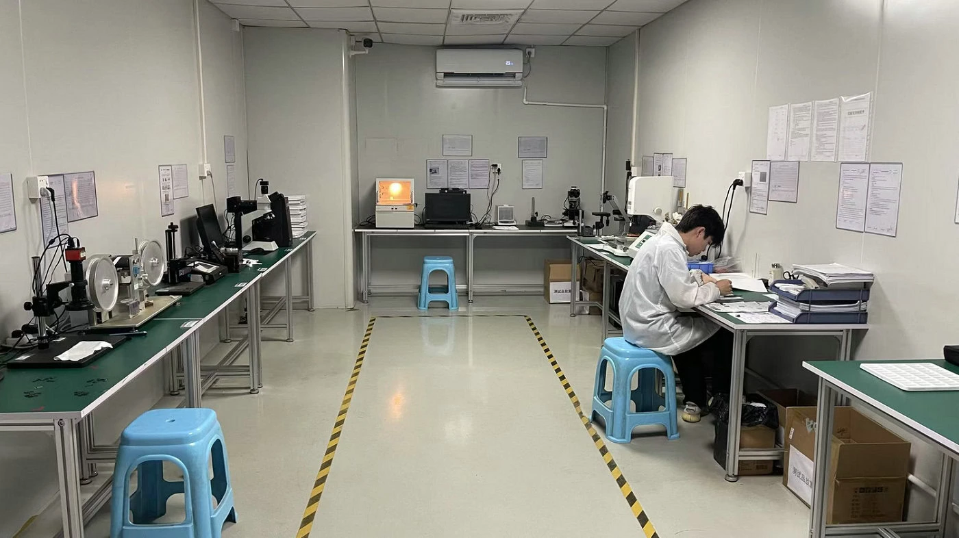
Inspection Planning Must Follow the Feature Review
Miniaturized component review is incomplete until the team decides how the critical feature will be measured, how the part will be held without damage, and what evidence is required during sampling and repeat production. Small bores, hooks, slots, contact faces, and positional relationships may require optical measurement, dedicated fixtures, functional gauges, or local post-processing before final acceptance.
The inspection method should be agreed before tooling release when measurement access, datum definition, feature protection, or coating thickness can affect the final result.