
MIM Design Guide · Shrinkage Compensation
MIM Shrinkage Compensation for Mold Scaling and Dimensional Control
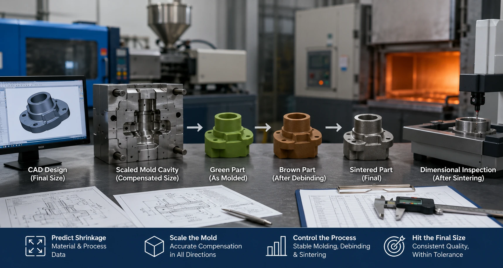
MIM shrinkage compensation is the design, tooling, and validation method used to offset the dimensional reduction that occurs when a molded MIM part is debound and sintered. The mold cavity is intentionally enlarged from the final drawing size, so the sintered metal part can approach the required dimensions after densification. For product engineers, the real question is not only “how much does MIM shrink?” but whether the part geometry, material, feedstock, wall thickness, gate location, sintering support, and inspection plan allow predictable dimensional control before mold release.
Quick answer: MIM shrinkage compensation is not a universal shrinkage percentage. It is a controlled loop that connects part design, material and feedstock assumptions, mold scaling, debinding and sintering behavior, first-sample measurement, and correction decisions before production release.
What Does Shrinkage Compensation Mean in MIM Design?
MIM shrinkage compensation means converting the required final part dimensions into an enlarged mold cavity size based on the expected dimensional reduction during debinding and sintering. In a MIM project, the final metal part is not the same size as the molded green part. The part is first injection molded from metal powder-binder feedstock, then binder is removed, and finally the part is sintered until the fine metal powder structure densifies.
From a design review perspective, three dimensional states should be separated clearly:
| Dimensional State | What It Means | Why It Matters for Shrinkage Compensation |
|---|---|---|
| Mold cavity size | The oversized tool cavity used to form the green part | This must account for expected shrinkage before tooling is released. |
| Green / brown part size | The intermediate part before final sintering | It is fragile and not the final inspection condition. |
| Final sintered size | The part after densification and shrinkage | This is the condition measured against the drawing. |
A common mistake is treating shrinkage compensation as a fixed percentage applied equally to every feature. In real projects, the nominal shrinkage factor is only the starting point. The supplier must also review geometry, local wall thickness, material behavior, gate and flow balance, support direction, datum strategy, and critical-to-function dimensions. If a feature controls assembly, sliding, sealing, bearing contact, or cosmetic acceptance, it may need more detailed review than a non-critical outside dimension.
Engineering point: Shrinkage compensation can bring the final part closer to target dimensions, but it does not remove all tolerance variation or correct poor geometry by itself. Tight features may still require better datum planning, local design changes, controlled sintering support, first-sample correction, or secondary machining.
Why Do MIM Parts Shrink During Debinding and Sintering?
MIM uses fine metal powder mixed with binder to create an injectable feedstock. During injection molding, this feedstock fills the cavity and forms a green part. During debinding, much of the binder is removed and the part becomes a porous brown part. During sintering, the powder particles bond and densify, reducing pore volume and causing the part to shrink.
This shrinkage is normal. It is not automatically a defect. The practical design issue is whether shrinkage is planned, compensated, measured, and corrected with a stable engineering process. Green part handling, debinding stability, setter contact, furnace loading, and inspection datum selection can all influence whether the final sintered part is dimensionally useful.
Shrinkage is expected. Uncontrolled dimensional error is the risk. A well-planned MIM project does not try to eliminate shrinkage; it accounts for shrinkage by confirming material choice, feedstock stability, part geometry, mold scaling, sintering support, and inspection method before final tooling decisions are made.
Public industry resources from MIMA and EPMA explain that MIM involves significant shrinkage during sintering and that this shrinkage must be controlled as part of the process. For a project-level decision, these references should be combined with drawing-based DFM review and supplier-specific validation.
Why Is MIM Shrinkage Predictable but Not Always Uniform?
MIM shrinkage can be predictable in a controlled process, but that does not mean every feature shrinks in exactly the same way. Many dimensional problems come from local shrinkage variation or distortion, not from a complete failure of the overall shrinkage factor.

| Factor | How It Affects Shrinkage | Design Review Concern | Suggested Next Reading |
|---|---|---|---|
| Material and feedstock | Different powder-binder systems may shrink differently. | Confirm material before mold scaling assumptions are fixed. | Material selection and MIM part quality |
| Green density | Uneven filling or packing can create local shrinkage variation. | Review injection molding stability and gate location. | Injection molding quality |
| Wall thickness | Thick and thin areas can densify and distort differently. | Avoid abrupt thick-to-thin transitions and uncontrolled mass concentration. | Wall thickness design |
| Gate and flow path | Flow imbalance may affect local green density. | Review critical dimensions near flow-sensitive zones. | MIM gate design |
| Sintering support | Contact, gravity, friction, setter contact, and support direction affect shape stability. | Review flatness, long spans, unsupported areas, contact surfaces, and setter direction before treating the issue as a shrinkage-factor error. | sintering support and distortion review |
| Holes and slots | Local geometry may shift, ovalize, or distort. | Review core pin strategy, hole distance, wall transition, and datum position. | Holes, slots, and undercuts |
MIMA design guidance discusses how wall thickness variation can contribute to distortion, internal stresses, cracking, sink marks, and non-uniform shrinkage. This is why shrinkage compensation must be reviewed as part of the part design, not only as a tooling calculation.
In production, the question is usually not “does this part shrink?” but “does this geometry allow stable, repeatable, measurable shrinkage?” That question should be answered before mold steel is cut, especially when the part contains thin walls, micro features, undercuts, small holes, or assembly-critical surfaces.
Which Drawing Features Need Shrinkage Compensation Review Before Tooling?
Not every dimension on a drawing has the same functional importance. Shrinkage compensation review should focus first on critical-to-function dimensions and features that can affect assembly, movement, sealing, location, flatness, or visual acceptance.

Assembly-critical dimensions
Any dimension that controls fit, alignment, movement, locking, sliding, or fastening should be clearly marked. If all tolerances are treated equally, the engineering team may spend effort controlling dimensions that do not affect function while missing the dimensions that determine assembly success.
Hole positions and center distances
MIM can produce small holes, slots, and complex features, but hole position and center distance should be reviewed carefully when holes are near thick sections, ribs, bosses, gate-sensitive areas, or unsupported spans.
Flatness and support-related surfaces
Flat surfaces can be sensitive to sintering support, friction, gravity, and wall thickness variation. A surface that appears simple in CAD may distort after sintering if it is long, thin, wide, or poorly supported.
Sliding, sealing, bearing, and cosmetic zones
Functional surfaces may need stricter dimensional control or secondary machining. Cosmetic surfaces may also need gate, support, and correction planning so that shrinkage correction does not create visible defects.
Critical Dimension Review Checklist
This checklist helps engineers decide which drawing features should be highlighted before mold scaling assumptions are locked.
| Review Question | Why It Matters |
|---|---|
| Are assembly-critical dimensions clearly marked? | Prevents over-control of non-critical dimensions and under-review of functional ones. |
| Are datums defined on stable surfaces? | Makes first-sample measurement feedback meaningful. |
| Are tight tolerances limited to functional areas? | Reduces unnecessary tooling correction, inspection burden, cost, and lead-time risk. |
| Are holes close to thick sections or ribs? | Local shrinkage variation may affect hole position or roundness. |
| Are long spans or flat areas unsupported? | Sintering distortion may be mistaken for shrinkage error. |
| Are cosmetic and functional surfaces separated? | Helps gate, support, and correction planning. |
| Are secondary machining areas identified? | Avoids relying on as-sintered accuracy where machining is more realistic. |
How Does Mold Scaling Work for MIM Shrinkage Compensation?
Mold scaling starts with the final part drawing and works backward to the mold cavity. The tool cavity is enlarged according to the expected shrinkage behavior of the material, feedstock, part geometry, and process route. The goal is to mold a green part that, after debinding and sintering, reaches the required final dimensions as closely as practical.

Basic mold scaling formula
For early design discussion, a simple linear scaling formula can explain the mold oversize logic:
Mold cavity dimension = final target dimension ÷ (1 − expected linear shrinkage fraction)
For example, if the final target dimension is 10.00 mm and the assumed linear shrinkage is 15%, the initial cavity estimate would be 10.00 ÷ 0.85 = 11.76 mm. This is only an engineering starting point. Actual mold scaling must be confirmed by material, feedstock, geometry, tooling design, sintering behavior, first-sample measurement, and supplier process validation.
Basic mold scaling logic
- The engineer reviews the final drawing dimensions, datums, and critical-to-function features.
- Material and feedstock assumptions are confirmed before mold scaling is fixed.
- Expected shrinkage behavior is estimated from material, feedstock, geometry, and process experience.
- Mold cavity dimensions are scaled larger than the final part.
- First sintered samples are measured against the approved drawing.
- Deviations are separated into global shrinkage error, local dimensional deviation, or distortion.
- Tooling, process, support, design, or secondary operation corrections are made if needed.
Why nominal shrinkage factor is only the starting point
A nominal shrinkage factor can guide initial mold scaling, but it does not replace design review. If the part has uneven wall thickness, local density variation, unsupported surfaces, or tight positional tolerances, the final result may not follow the nominal factor perfectly.
Why the mold should allow trial correction
Tooling should be reviewed with the expectation that first samples may require measurement-based correction. In practice, correction may involve steel adjustment, process review, support modification, design change, or machining allowance. If a supplier treats shrinkage compensation as a fixed number with no feedback loop, the project risk is higher.
How Should First Sintered Samples Be Measured and Corrected?
First sintered samples should be measured against the approved drawing, datums, and critical dimensions. The purpose is not only to confirm whether the part is acceptable. The purpose is to understand what kind of dimensional deviation has occurred and which correction route is technically appropriate.

Separate global shrinkage error from local distortion
This table separates common first-sample conditions so dimensional correction is not treated as a simple pass-or-fail decision.
| Condition | Typical Meaning | Engineering Response |
|---|---|---|
| Global size error | The whole part is generally oversized or undersized. | Recheck shrinkage factor, material/feedstock assumptions, and tooling compensation. |
| Local dimensional deviation | One feature or region is out of tolerance. | Review wall thickness, gate/filling, local density, and feature geometry. |
| Distortion or warpage | Shape, flatness, or position is unstable. | Review support direction, setter contact, gravity effect, and part geometry. |
First Sample Dimensional Deviation: Possible Cause and Review Action
The correction route should be selected after reviewing the measured deviation pattern, not by assuming every issue requires tool steel correction.
| Observed Issue | Possible Cause | Review Action |
|---|---|---|
| Overall part oversized | Shrinkage lower than expected | Recheck shrinkage factor and tooling correction plan. |
| Overall part undersized | Shrinkage higher than expected | Review material, feedstock, debinding, and sintering behavior. |
| Hole position shifted | Local distortion, support issue, or wall transition effect | Check support direction, wall thickness transition, datum strategy, and local correction option. |
| Flat surface warped | Unsupported span, friction, or thick-to-thin transition | Review setter/support design, part geometry, and whether a dedicated support plan is needed. |
| One feature out of tolerance | Local density variation or geometry constraint | Review gate/filling, tooling correction, or secondary machining. |
| Critical surface unstable | As-sintered tolerance may not be realistic | Consider machining, sizing, or design tolerance adjustment. |
A useful first-sample report should show measured values, drawing references, datums, deviation patterns, and proposed action. Without this feedback loop, shrinkage compensation becomes guesswork. A dimensional issue should not automatically trigger mold correction until the team has separated global scale error from local distortion, fixture contact, support effect, or unrealistic tolerance assignment.
How Is Shrinkage Compensation Different from MIM Tolerances and Distortion Control?
Shrinkage compensation, tolerance control, and distortion control are related, but they are not the same engineering problem. This distinction is important because the correct solution depends on the root cause of the dimensional issue.

The table below clarifies page boundaries so this shrinkage compensation guide does not replace the dedicated tolerance, sintering support, or DFM pages.
| Topic | What It Controls | Main Question | Where to Learn More |
|---|---|---|---|
| Shrinkage compensation | Expected size reduction from molding to sintered part | Will the mold scaling bring the final part close to the target size? | This page |
| MIM tolerances | Acceptable final dimensional variation | What variation is realistic for as-sintered or machined features? | MIM tolerances |
| Distortion control | Shape, flatness, warpage, and positional stability | Will the part hold its intended shape during sintering? | sintering support for flatness and distortion control |
| DFM review | Overall manufacturability before tooling | Should the design, tolerance, material, or process plan be changed? | DFM for MIM |
A supplier may compensate the mold correctly, but the part may still show local distortion. A tolerance may be specified tightly, but the geometry may not allow that tolerance to be held as-sintered. A flatness problem may require support or design changes, not only shrinkage factor adjustment.
Practical strategy: For critical dimensions, the correct plan may combine better datum definition, revised wall thickness transitions, support direction planning, mold correction after first samples, secondary machining, or realistic tolerance adjustment for non-critical features. Shrinkage compensation should not be used to promise that every tight feature can remain as-sintered.
What Design Mistakes Make Shrinkage Compensation More Difficult?
Shrinkage compensation becomes more difficult when the part design forces the process to solve problems that should have been addressed before tooling. The following mistakes are common in early MIM project reviews.
| Design Mistake | Why It Creates Risk | Better Review Approach |
|---|---|---|
| Using one shrinkage number for every feature | Local geometry may behave differently from the overall part. | Review material, wall thickness, support, and geometry together. |
| Applying tight tolerances everywhere | Increases tooling correction, inspection burden, cost, and lead time. | Mark only critical-to-function dimensions tightly. |
| Ignoring thick-to-thin transitions | Creates local shrinkage variation and distortion risk. | Add transitions, coring, or wall thickness adjustment where feasible. |
| Placing critical holes near heavy sections | Local mass differences may affect hole position or roundness. | Review hole location, boss design, and datum plan. |
| Changing material after tooling assumptions are fixed | Shrinkage behavior may no longer match mold scaling. | Confirm material before mold release. |
| Forgetting sintering support direction | Warpage may be mistaken for shrinkage error. | Review support surfaces before final tooling. |
| No clear datum strategy | First-sample measurement feedback becomes unclear. | Define stable datums and inspection references before tooling. |
A common mistake is treating the drawing as a list of independent dimensions. In MIM, dimensions interact through material flow, green density, wall thickness, sintering support, and shrinkage. The design should be reviewed as a system before the part moves into tooling.
What Information Should You Send for Shrinkage and Tolerance Review?
For a useful shrinkage compensation review, the supplier needs more than a part name or product photo. The more clearly the engineering requirements are defined, the more accurately the team can review tooling risk, shrinkage behavior, critical dimensions, and tolerance strategy.

RFQ Input Checklist for Shrinkage Compensation Review
The following inputs help the engineering team review mold scaling, dimensional risk, tolerance feasibility, inspection priorities, and possible secondary operation needs before tooling.
| Information to Provide | Why It Matters |
|---|---|
| 2D drawing with tolerances | Confirms critical and non-critical dimensions. |
| 3D CAD file | Helps review geometry, wall thickness, holes, ribs, and support risk. |
| Material grade or target performance | Affects expected shrinkage, strength, corrosion resistance, hardness, and post-processing. |
| Critical-to-function dimensions | Guides tooling compensation and inspection priority. |
| Datum and inspection method | Makes first-sample measurement feedback meaningful. |
| Surface finish or cosmetic zones | Helps plan gate, support, correction, and finishing strategy. |
| Application environment | Helps review material, strength, corrosion, wear, and temperature requirements. |
| Estimated annual volume | Affects tooling, inspection, and cost strategy. |
| Project stage | Helps decide whether the review should focus on concept, prototype, trial, or production release. |
| Existing manufacturing issue | Useful when converting from CNC, casting, stamping, or another process. |
For validation-stage projects, the best time to review shrinkage compensation is before mold release. At that point, design changes are still easier than correcting dimensional risk after tool steel has been cut.
Composite Field Scenario: Shrinkage Risk in a Small Precision MIM Bracket
This composite field scenario is provided for engineering training. It does not represent a single customer project, order, or disclosed production case.
What problem occurred
A small precision MIM bracket had two assembly holes, one thick mounting boss, a thin connecting arm, and a flat support surface. After first sintered samples, the overall part size was close to target, but one hole center distance and one flatness zone required further review.
Why it happened
The issue was not simply “wrong shrinkage rate.” The thick boss created a local mass difference near one hole, while the thin arm and flat surface were sensitive to support direction during sintering.
What the real system cause was
The global shrinkage compensation was reasonably close, but local shrinkage variation and support-related distortion affected critical features. Because the datum strategy was not clear enough at the beginning, the first measurement review required extra clarification.
How it was corrected and prevented
The team separated global shrinkage from local distortion, reviewed the wall transition near the boss, confirmed which hole distance was function-critical, adjusted the support plan, and clarified tolerance priority. Before tooling, similar projects should mark critical dimensions, define stable datums, review thick-to-thin transitions, identify support surfaces, and confirm which features can remain as-sintered and which may require secondary machining.
Standards and Technical Reference Notes
MIM shrinkage compensation should be reviewed using project-specific drawings, material requirements, tolerance expectations, and supplier process experience. Public industry resources can guide evaluation, but they should not replace drawing-level DFM review, material validation, first-sample inspection, or approved production control plans.
| Source | Why It Is Relevant | Correct Use on This Page |
|---|---|---|
| MIMA Process Overview | Explains the MIM route from feedstock and injection molding to debinding, sintering, shrinkage, and densification. | Used as a process-route reference for why shrinkage occurs and why it must be planned. |
| MIMA Complex Designs with MIM | Discusses design factors such as wall thickness variation, distortion, non-uniform shrinkage, and tolerance control. | Used to support design review logic, not to guarantee a universal shrinkage value. |
| EPMA Metal Injection Moulding Overview | Explains MIM as a powder-binder feedstock, injection molding, debinding, and sintering process with controlled shrinkage. | Used as a general industry reference for the MIM process and controlled sintering shrinkage. |
| MPIF Standards | Provides standards resources for powder metallurgy and MIM materials, including material specification references. | Used for material and specification context. It should not be interpreted as a fixed shrinkage-rate guarantee. |
Publishing note for engineering accuracy: Do not present a single shrinkage percentage as a universal rule. Actual shrinkage assumptions should be confirmed through material, feedstock, geometry, tooling, sintering, first-sample validation, and the project’s approved inspection requirements. MPIF, MIMA, and EPMA references support material and process understanding; they do not replace project-specific mold scaling validation.
FAQ About MIM Shrinkage Compensation
What is MIM shrinkage compensation?
MIM shrinkage compensation is the tooling and process planning used to offset the dimensional reduction that occurs during debinding and sintering. The mold cavity is made larger than the final part so that the sintered part can approach the required drawing dimensions.
How much do MIM parts shrink during sintering?
MIM parts usually experience significant shrinkage during sintering. Public industry resources often describe typical shrinkage ranges in the high-teens to low-twenties percentage range, depending on binder volume and process conditions. Final shrinkage assumptions should always be confirmed by material, feedstock, geometry, and supplier process experience.
How do you calculate MIM shrinkage compensation for mold design?
A basic starting formula is: mold cavity dimension = final target dimension ÷ (1 − expected linear shrinkage fraction). This formula only explains initial mold oversize logic. Actual compensation must be validated by material, feedstock, part geometry, tooling design, sintering behavior, first-sample measurement, and supplier process capability.
Is MIM shrinkage the same in every direction?
Not always. A well-controlled MIM process can make shrinkage repeatable, but local geometry, wall thickness variation, green density, sintering support, and friction can create local dimensional variation or distortion.
Can shrinkage compensation guarantee tight tolerances?
No. Shrinkage compensation improves the chance that the final part approaches the target size, but tolerance capability also depends on geometry, material, tooling, sintering support, inspection method, and process stability. Some critical features may require secondary machining.
What causes shrinkage-related dimensional problems in MIM?
Common causes include unstable feedstock behavior, green density variation, abrupt wall thickness changes, unsupported flat surfaces, thick bosses near critical holes, unclear datums, unrealistic tolerances, and late material changes after tooling assumptions have been fixed.
Should critical dimensions be machined after sintering?
It depends on the tolerance, function, material, cost target, and production volume. Critical bores, sealing surfaces, sliding surfaces, bearing areas, and precision datum features may require machining when as-sintered control is not enough.
What should I send for a shrinkage compensation review?
Send 2D drawings, 3D CAD files, material requirements, critical dimensions, tolerances, datums, surface requirements, application environment, estimated annual volume, and the current project stage.
Review Shrinkage, Tolerance, and Tooling Risk Before Mold Release
If your MIM part includes tight assembly dimensions, small holes, thin walls, thick bosses, flatness requirements, sliding surfaces, sealing areas, or cosmetic surfaces, submit your drawing before tooling starts.
Please provide 2D drawings, 3D CAD files, material targets, tolerance requirements, functional surfaces, application environment, and estimated annual volume. XTMIM can review shrinkage compensation risk, tooling scaling assumptions, tolerance feasibility, sintering support concerns, and whether secondary machining or design adjustment should be considered before mold release.