
DFM for MIM: Design Review Before Tooling
DFM for MIM is a drawing- and CAD-based manufacturability review completed before mold approval and tooling investment. It checks whether a part can be molded, ejected, handled in the green state, debound, sintered, supported, measured, and produced repeatedly. The review identifies geometry, gate, shrinkage, datum, tolerance, surface, and secondary-operation risks while design changes are still practical. It is especially useful for thin walls, undercuts, side holes, cosmetic faces, flatness requirements, tight tolerances, or CNC-to-MIM conversions.
When Should a MIM Part Go Through DFM Review?
A MIM part needs DFM review when CAD geometry may create risk during molding, green-part handling, debinding, sintering, or inspection. The decision is not simply whether the shape can be molded, but whether the complete process can deliver stable dimensions, acceptable surfaces, realistic yield, and a viable cost structure.
Suitability depends on material performance, shape complexity, expected volume, and component economics. The review therefore connects geometry with feedstock behavior, tool motion, gate location, green-part strength, support strategy, shrinkage, tolerance, and inspection.
Parts That Usually Need MIM DFM Review
- Thin walls combined with thicker bosses, local mass, or sudden wall transitions.
- Cross holes, side holes, slots, undercuts, small hooks, or fragile micro features.
- Cosmetic or customer-facing surfaces where gate marks, parting lines, or support marks are unacceptable.
- Functional faces requiring flatness, parallelism, positional stability, or controlled assembly fit.
- Tight datum-based tolerances that may not be reliable if the datum is unstable after sintering.
- Large flat surfaces, cantilevered sections, or asymmetric geometry sensitive to sintering distortion.
- Existing CNC-machined parts being redesigned for MIM production.
- Parts requiring post-sinter machining, heat treatment, polishing, coating, plating, or passivation.
Parts That May Not Be Good MIM Candidates
A good DFM review should also identify when MIM is not the most practical route. A part may need redesign or another process when it is very large and geometrically simple, needed only in very low annual quantity, dependent on broad machined surfaces, or unable to accept any gate mark, parting line, support contact, tolerance adjustment, or secondary operation mark.

Use these signals as screening triggers rather than stand-alone approval criteria. The complete disposition belongs in the MIM DFM review matrix, where geometry is evaluated together with tooling, gate, handling, sintering, shrinkage, tolerance, and inspection.
For feature-specific limits, review MIM part design, wall thickness risk, and as-sintered and machined tolerance strategy.
What Information Should Be Prepared for a Useful MIM DFM Review?
A useful MIM DFM review depends on more than a 3D model. A CAD file shows shape, but it does not always explain function, critical dimensions, inspection priorities, cosmetic expectations, application load, annual volume, or acceptable secondary operations. Missing project information often leads to vague feedback, over-conservative assumptions, or a quotation that does not reflect the real production risk.
Drawing and CAD Inputs
Before requesting a DFM review, prepare the following information:
- 2D drawing with dimensions, tolerances, datums and technical notes.
- 3D CAD file in a usable engineering format.
- Material grade or target mechanical, corrosion, magnetic or wear property.
- Critical-to-function dimensions and assembly fit requirements.
- Surface finish, cosmetic surface notes, heat treatment or coating requirements.
- Estimated annual volume or production quantity range.
- Application environment, including load, wear, corrosion, temperature or mating parts.
- Current manufacturing process if the part is being converted from CNC, casting, stamping or assembly.
What Engineers Cannot Judge from a Drawing Alone
A common mistake is assuming that every dimension on a drawing has the same functional importance. In production, this is rarely true. Some dimensions control assembly, some only define appearance, and others are reference dimensions that should not drive tooling or machining decisions.
Cosmetic surfaces, assembly direction, inspection method, critical holes, functional datums, mating part interfaces and whether post-sinter machining is acceptable.
The tooling concept, gate location, sintering support, tolerance strategy and secondary operation plan may be based on wrong assumptions.
The table below shows why each RFQ input affects DFM quality and quotation accuracy.
| Required Input | Why It Matters for MIM DFM |
|---|---|
| 2D drawing | Defines tolerances, datums, drawing notes and inspection intent. |
| 3D CAD file | Helps evaluate geometry, parting direction, tool action, local mass and feature interaction. |
| Material requirement | Affects shrinkage, strength, corrosion resistance, heat treatment, finishing and process route. |
| Critical dimensions | Separates functional requirements from non-critical geometry and avoids over-controlling every feature. |
| Surface requirements | Controls gate location, parting line position, support contact, polishing and coating decisions. |
| Annual volume | Helps judge whether MIM tooling cost and engineering validation effort are justified. |
| Application background | Explains load, wear, temperature, corrosion, assembly and field-use conditions. |
| Secondary operation requirements | Affects machining allowance, datum planning, cost, lead time and inspection sequence. |
For project preparation, use the MIM DFM design checklist, the MIM tolerance and shrinkage checklist, or the MIM RFQ preparation guide.
How Engineers Review Part Geometry Before MIM Tooling
Geometry review is the first major part of MIM DFM, but it should not be treated as a simple “can this shape be molded?” question. A part may be moldable but still risky during green-part ejection, degating, debinding, sintering, or final inspection. Before tooling, the key question is whether the full feature combination can survive the process route and still meet the drawing intent.

Overall Geometry and Feature Combination
MIM is often attractive when a small metal part combines multiple complex features into one component. However, DFM review should judge the feature combination, not only each feature alone. A thin arm, a cross hole, a cosmetic face and a tight datum may each be manageable separately. When combined in one part, they may create tooling complexity, filling imbalance, sintering support limitations and inspection instability.
Wall Transition, Local Mass and Fragile Areas
Wall thickness is not only a filling issue. Uneven wall mass may affect debinding, sintering shrinkage and distortion. Thick local bosses can retain binder differently from thin sections. Unsupported thin features may deform during ejection or tray loading before sintering.
From a DFM standpoint, engineers should check thick-to-thin transitions, heavy bosses connected to thin walls, sharp internal corners, long unsupported ribs or arms, and areas where local mass may slow debinding. Detailed wall design rules belong on the wall thickness risk review page.
Holes, Slots, Undercuts and Tool Motion
Holes, slots and undercuts are not automatically good or bad. Their manufacturability depends on direction, size, location, depth, wall support, tool access and whether the feature creates a weak green-part area.
DFM review should check whether a hole can be formed with a straight core pin, whether a side action or insert is required, whether a slot creates flash or breakage risk, and whether an undercut is justified by function. Detailed feature-specific guidance belongs on the holes, slots, and undercut feasibility page.
How DFM Connects Part Design to Mold, Gate and Green Part Handling
A MIM drawing cannot be separated from tooling. Once mold design is fixed, many cost, quality and surface decisions become difficult to change. This is why DFM review should happen before mold concept approval, not after first samples reveal avoidable risks.
Tooling Complexity Before Mold Design Is Fixed
Mold design review should consider parting line location, slide or lifter requirements, insert and core pin strategy, ejection direction, ejector contact area, flash-sensitive surfaces, tool maintenance risk and avoidable mold cost.
A part with multiple side features may still be possible by MIM, but every slide, insert or difficult core pin increases engineering risk. The DFM question is not simply “can we mold this?” It is “does this tool concept support stable production at the expected volume and quality level?” For deeper tooling structure guidance, review MIM mold design impact.
Gate Location, Flow Path and Protected Surfaces
Gate design affects both manufacturing and customer-facing quality. A gate placed on a functional or cosmetic surface may create removal marks, local distortion or finishing cost. A poor flow path may increase short shots, weld lines, density variation or dimensional instability.
During DFM review, engineers should identify protected functional surfaces, cosmetic surfaces, possible gate mark tolerance, flow length, filling balance, degating method and whether gate removal affects dimension or appearance. For detailed gate strategy, review gate location and flow path review.
Green Part Handling Risk After Molding
The green part is not final metal. Before debinding and sintering, it is more fragile than the sintered component. Thin arms, unsupported pins, small hooks and sharp details may survive mold filling but break during ejection, trimming, inspection or tray loading.
DFM should therefore consider handling, not only mold filling. A design that looks manufacturable in CAD may still need feature reinforcement, support surface changes, gate relocation or handling strategy.
How DFM Reviews Debinding, Sintering Support and Shrinkage Risk
A part that can be injection molded may still fail DFM review if debinding or sintering risk is not controlled. MIM DFM must account for the full process route: feedstock molding, binder removal, sintering shrinkage, support strategy and dimensional verification.

Debinding and Sintering Are Part of DFM, Not Only Process Control
Debinding removes binder from the molded green part before sintering. If the part has thick local sections, trapped binder paths, sharp transitions or unsupported features, the risk may not appear during molding but can show up later as cracking, distortion or inconsistent final dimensions.
MIMA describes the MIM route as feedstock preparation, molding, binder removal and sintering. It also identifies the molded part as a green part and the part after debinding as a brown part before final sintering. This process sequence is why MIM DFM must evaluate more than mold filling.
Sintering Support and Flatness Risk
Sintering support is a design issue, not only a furnace issue. Large flat surfaces, cantilevers, asymmetric geometry, long thin sections and parts with unstable contact areas may distort if the support strategy is not considered before tooling.
DFM review should identify which surface can contact a setter, whether support marks are acceptable, whether a critical surface should avoid support contact, and whether flatness or straightness depends on support orientation. Detailed support strategy belongs on the sintering support and flatness risk page.
Shrinkage Compensation and Critical Dimension Prediction
MIM parts undergo significant shrinkage during sintering. Tooling compensation must consider material system, feedstock behavior, geometry, section thickness, furnace process, support orientation and measurement datum. The review should separate dimensions that can be controlled as-sintered from dimensions that may need machining or tighter inspection strategy.
DFM should not promise that every critical dimension can be held directly after sintering. Instead, it should define where shrinkage risk exists and how tooling, process and inspection planning should manage it. For deeper guidance, review shrinkage compensation before tooling and how feedstock affects MIM part quality.
How DFM Sets Tolerance, Datum, Inspection and Secondary Operation Strategy
Tolerance review is one of the most important parts of MIM DFM. The issue is not whether MIM can produce precision metal parts. The issue is which dimensions should be controlled by the MIM process, which should be adjusted through tooling compensation, which should be measured from stable datums, and which may require secondary machining.
As-Sintered Tolerance vs Machined Tolerance
As-sintered dimensions are controlled through tooling, feedstock, shrinkage behavior, sintering support and process consistency. Machined dimensions are controlled after sintering through operations such as drilling, reaming, tapping, grinding, milling or lapping.
DFM should classify drawing dimensions into critical-to-function dimensions, assembly fit dimensions, cosmetic dimensions, reference dimensions, dimensions suitable for as-sintered control, dimensions requiring machining allowance and dimensions needing inspection clarification. A common mistake is applying tight tolerance to every feature. This can increase tooling complexity, inspection cost and secondary machining without improving the actual function of the part. For detailed tolerance strategy, use the as-sintered and machined tolerance review page.
Datum and Inspection Planning
Datums must be manufacturable and measurable. If the drawing uses a small, flexible, unsupported or distortion-sensitive feature as a datum, inspection may become unstable even if the part can be produced.
DFM review should check whether datums are stable after sintering, whether inspection surfaces are accessible, whether support contact affects the datum surface, whether machined surfaces should become final inspection datums, and whether cosmetic and functional requirements are separated clearly.
Secondary Operations Should Be Planned, Not Added Late
Secondary operations may be useful, but they should be planned early. Late machining decisions can create fixture challenges, datum conflicts, added cost and longer lead time. Common review points include machining allowance, hole reaming or tapping, critical surface grinding, heat treatment distortion, polishing, plating buildup and final inspection after finishing.
For cost-related decisions, review MIM design for cost and how part dimensions affect final MIM part quality.
How DFM Decisions Affect Cost Without Over-Designing the Part
DFM affects cost because manufacturing risk becomes cost in tooling, inspection, secondary operations, yield loss, trial corrections and production control. However, DFM should not simply make the part easier by removing every useful feature. The goal is to protect function while avoiding unnecessary manufacturing difficulty.
The table below shows common cost drivers found during MIM DFM review and how engineers may reduce avoidable cost without weakening the part function.
| DFM Finding | Why It Raises Cost | Possible Review Action |
|---|---|---|
| Excessively tight non-functional tolerances | More inspection, machining and process control. | Relax or reclassify non-critical dimensions. |
| Complex slide or insert requirement | Higher mold cost and maintenance risk. | Redesign feature direction or simplify undercut where function allows. |
| Gate mark on protected surface | Extra finishing or rejection risk. | Move gate to a non-functional surface or revise the protected surface priority. |
| Poor sintering support surface | Flatness correction, support mark control and yield risk. | Add or define acceptable support contact before tooling. |
| Many post-sinter machining areas | Longer cycle time, more fixtures and higher unit cost. | Limit machining to dimensions that are truly critical to function. |
| Over-specified material | Higher material, heat treatment or finishing cost. | Review the actual mechanical, corrosion, magnetic or wear requirement. |
DFM can reduce cost when it simplifies tool motion, reduces unnecessary secondary operations, separates critical and non-critical dimensions, protects only truly functional or cosmetic surfaces, improves sintering support, reduces trial correction loops and aligns material choice with real application conditions.
MIM DFM Review Matrix Before Tooling
This matrix is the core of a practical MIM DFM review. It helps design engineers identify which risks should be resolved before mold design and which topics should be reviewed in more detail on dedicated design pages.

The table below maps the major DFM review areas to their manufacturing risks and the related detailed guides in this MIM design cluster.
| Review Area | What Engineers Check | Manufacturing Risk | Expected DFM Output | Related Detailed Guide |
|---|---|---|---|---|
| Part geometry | Feature combination, thin sections, sharp corners, fragile areas. | Filling issue, cracking, green-part damage. | Confirm whether geometry is ready for tooling or needs redesign. | MIM Part Design |
| Wall thickness | Thick-to-thin transition, local mass, unsupported thin areas. | Debinding issue, warpage, shrinkage variation. | Identify wall transitions that need thinning, coring, or support planning. | Wall Thickness Design |
| Holes, slots and undercuts | Core pin direction, side action, demolding, flash risk. | Tool complexity, feature breakage, mismatch. | Decide whether features are molded, redesigned, or machined after sintering. | Holes, Slots and Undercuts |
| Mold concept | Parting line, slides, inserts, ejection, tool access. | Mold cost, flash, surface marks, maintenance risk. | Define tooling complexity and surface risks before mold approval. | MIM Mold Design |
| Gate design | Gate mark, flow path, degating, protected surfaces. | Short shot, cosmetic defect, local damage. | Confirm acceptable gate areas and avoid functional or cosmetic conflict. | Gate Design |
| Green part handling | Ejection, trimming, degating, tray loading, fragile features. | Breakage, deformation, hidden damage. | Flag fragile areas that need support, feature adjustment, or handling control. | Injection Molding Quality Review |
| Debinding | Thick sections, binder removal path, cracking risk. | Internal defect, deformation, process instability. | Identify local mass and binder-removal risks before sample trial. | Debinding and Sintering Quality |
| Sintering support | Support surface, setter contact, cantilever, flatness. | Distortion, flatness loss, support marks. | Define support surface, support mark acceptance, and flatness risk. | Sintering Support |
| Shrinkage | Critical dimensions, mold scale, trial correction. | Dimensional drift, tooling correction delay. | Separate as-sintered dimensions from dimensions needing correction or machining. | Shrinkage Compensation |
| Tolerance and datum | Functional dimensions, inspection datums, measurement access. | Over-cost, unstable inspection, rejection risk. | Clarify tolerance priority, datum stability, and inspection method. | MIM Tolerances |
| Secondary operations | Machining allowance, finishing, heat treatment, coating. | Cost increase, datum conflict, lead time impact. | Plan machining, finishing, heat treatment, and final inspection sequence. | Design for Cost |
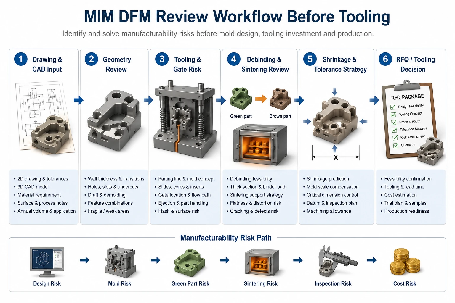
DFM Review Workflow: From Drawing Review to Tooling Decision
A strong MIM DFM review should follow a structured workflow. Without a workflow, design feedback can become scattered and difficult to act on.
Review drawings, CAD files, material requirements, tolerance notes, surface requirements, application background and expected volume.
Screen geometry, wall transitions, holes, undercuts, gates, green handling, debinding, sintering support, shrinkage and datum stability.
Separate risks into must-modify, tooling-managed, process-managed, secondary-operation, customer-confirmation and trial-validation items.
Align mold concept, gate strategy, machining allowance, inspection plan, material route, finishing and cost assumptions.
Plan sample validation for shrinkage, flatness, feature quality, surface condition, measurement stability and correction needs.
Confirm whether the part is ready for tooling, needs redesign, requires secondary operations, or should be compared with another process.
Representative Engineering Scenario: A Part That Looks Moldable but Fails DFM Review
Scenario disclosure: This representative scenario combines common MIM DFM risk patterns for explanation and is not presented as a specific customer project. A small metal connector appears suitable for MIM because it combines complex geometry and several integrated features. It also includes a broad flat surface, two small side holes, a thin cantilevered section, and a critical assembly hole.

The case logic below explains why “moldable in CAD” is not the same as “ready for MIM tooling.”
| Case Point | Engineering Interpretation |
|---|---|
| What problem occurred | The final geometry looked moldable, and each feature seemed possible when reviewed separately. |
| Why it happened | The drawing was created from a final-shape mindset and did not fully consider green-part strength, gate position, sintering support or inspection datum stability. |
| What the real system cause was | The combined risk came from an unsupported thin section, a critical hole near a shrinkage-sensitive region, a broad flat surface needing support, and unclear datum strategy. |
| How it was corrected | The support surface was redefined, the gate was moved away from the functional face, the hole tolerance strategy was separated into as-sintered and machined options, and the datum scheme was clarified. |
| How to prevent recurrence | Do not approve a MIM drawing only because the final geometry looks moldable. Review tooling, support, shrinkage, tolerance and inspection together before mold design. |
MIM DFM Checklist Before RFQ
Use this checklist before requesting quotation or tooling review. It helps the engineering team identify manufacturing risk earlier and provide more useful feedback.

Provide the 2D drawing, 3D CAD model, material requirement, critical dimensions, datum scheme, and surface or finishing notes.
Explain expected annual volume, application conditions, mating interfaces, current manufacturing route, and any cost or quality problem driving the review.
Use the MIM DFM design checklist for the full item-by-item review, or the MIM suitability checklist when the process choice is not yet confirmed.
Send Your Drawing for MIM DFM Review
Use this review when your project is before mold approval, CNC-to-MIM conversion, first sample correction, or production planning for a small complex metal part with thin walls, undercuts, tight tolerances, flatness requirements, cosmetic surfaces or secondary machining needs.
Please provide 2D drawings, 3D CAD files, material requirements, critical tolerances, surface finish needs, estimated annual volume and application background. XTMIM will review process suitability, tooling risk, gate location, green-part handling, debinding and sintering risk, shrinkage compensation, tolerance strategy, secondary operation needs and inspection feasibility before mold design or production planning.
FAQs About DFM for MIM
What is DFM for MIM?
DFM for MIM is a manufacturability review that checks whether a metal injection molded part can be molded, handled, debound, sintered, measured and produced consistently before tooling is finalized.
When should DFM review be done for a MIM part?
DFM review should be done before mold design approval, quotation finalization and tooling investment. It is especially important when the part has thin walls, undercuts, tight tolerances, critical surfaces, flatness requirements or conversion from CNC machining.
Is MIM DFM the same as a MIM design guide?
No. A MIM design guide explains design principles. MIM DFM applies those principles to a specific drawing, CAD model, material requirement, tolerance plan and production expectation.
What files are needed for MIM DFM review?
A useful review normally requires a 2D drawing, 3D CAD file, material requirement, critical dimensions, surface requirements, finishing requirements, estimated annual volume and application background.
What output should I expect from a MIM DFM review?
A practical review should identify whether the part is ready for tooling, needs design modification, requires secondary operations, has gate or support restrictions, needs tolerance clarification, or should be validated through first-sample inspection.
Can DFM review confirm whether a tolerance can be as-sintered?
DFM review can identify whether a tolerance may be suitable for as-sintered control or whether secondary machining may be needed. Final capability depends on material, geometry, shrinkage behavior, support strategy, inspection method and production validation.
Does DFM review reduce tooling cost?
It can reduce avoidable tooling cost by simplifying slides, inserts, gate strategy, support surfaces, machining allowance and non-critical tolerances. It does not automatically reduce cost if the part function truly requires complex tooling or tight control.
Can a CNC part be redesigned for MIM?
Yes, but it should not be copied directly into MIM tooling. CNC-to-MIM conversion should review feature integration, wall transition, gate location, shrinkage, datum strategy, tolerance priority, secondary machining and expected volume.
Does passing DFM review guarantee zero defects?
No. DFM review reduces known risks before tooling, but final validation still depends on tooling quality, feedstock behavior, debinding and sintering control, sample inspection and production process stability.
Engineering Review, Standards and Technical References
MIM DFM review should be based on the actual drawing, CAD model, material requirement, tolerance plan and application environment. Standards and industry references can support material specification and design understanding, but they should not replace supplier-specific DFM review.
Standards and design references can support early DFM decisions, but final project feedback still depends on a drawing-based review of geometry, material, tolerances, tooling, secondary operations, and inspection requirements. For XTMIM’s review scope, required project inputs, and expected feedback before tooling, see our MIM engineering review capability.
MPIF Standard 35-MIM: Relevant for MIM material specification and material property reference. It supports material selection and material discussion, but it should not be used as a universal approval rule for geometry, tooling, tolerance or production feasibility.
MIMA design and process references: Relevant for design context, MIM suitability, feedstock preparation, molding, green part handling, binder removal, sintering and process-aware design review.
Project-specific confirmation: Final manufacturability, tolerance capability and production strategy should still be confirmed through drawing review, mold design review, trial sample inspection and customer application requirements.
External references: MPIF Standards, MPIF Standard 35-MIM, MIMA Designing with MIM, MIMA Process Overview: MIM.