Suitability Screen
Is Metal Injection Molding Suitable for Your Part?
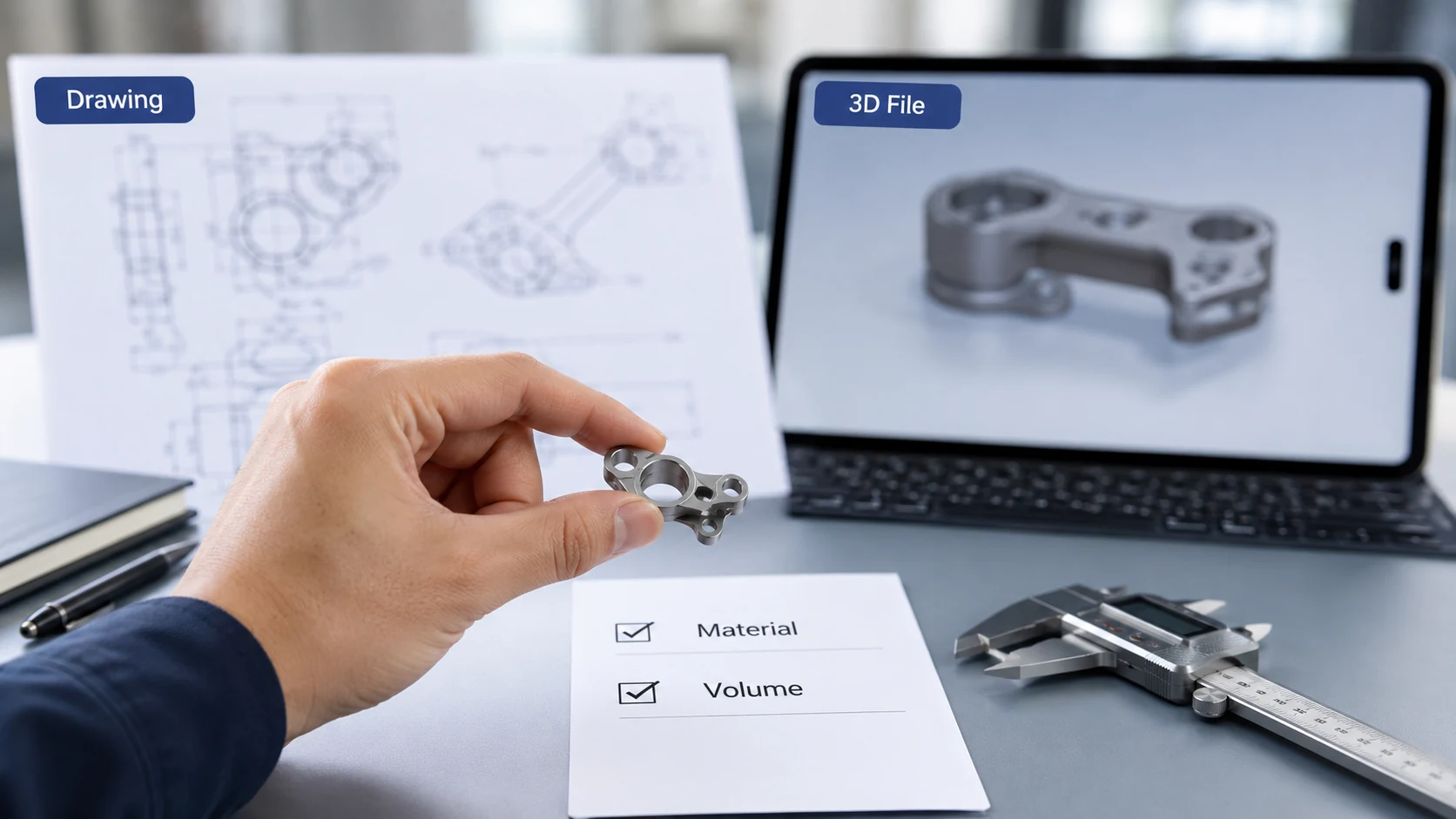
Before starting tooling or quotation, MIM suitability should be reviewed based on part geometry, annual volume, material target, shrinkage behavior, tolerance requirements, and finishing expectations. MIM is strongest when the part combines enough complexity, repeat demand, and feature integration to justify tooling, process development, and sintering control.
For a focused review of MIM benefits, trade-offs, and project risk boundaries, see the metal injection molding advantages and limitations guide before deciding whether a drawing should move into tooling.
For a deeper application-level review, see our metal injection molding applications guide, which explains suitable part types, common application conditions, material requirements, tolerance planning, manufacturing risks, and RFQ review factors before tooling.
✓
Usually a Good Fit for MIM
- Small complex metal parts with repeat production demand
- Thin walls, holes, slots, ribs, bosses, undercuts, or integrated features
- Components where near-net shape can reduce CNC machining time
- Parts that combine multiple functions into one molded component
- Projects with clear material, tolerance, finishing, and assembly requirements
- Programs where tooling cost can be justified by annual volume and part complexity
–
Usually Not a Good Fit for MIM
- Large, heavy, or simple metal parts with low geometric complexity
- Very low annual quantity that cannot justify tooling and process development
- Designs that are still changing frequently before production intent is clear
- Oversized thick sections or long thin features with high sintering distortion risk
- Parts requiring extremely tight tolerance everywhere without secondary correction
- Geometry that can be produced more economically by stamping, casting, PM, or CNC
Engineering note: MIM should be screened before tool kickoff, not after first samples fail dimensional review. A drawing-based review helps confirm whether geometry, shrinkage behavior, material route, tolerance strategy, and finishing requirements can support a stable MIM production path.
Not Sure Whether Your Part Fits MIM?
Send your drawing, target material, estimated annual volume, and critical dimensions for an engineering review before tooling or RFQ.