
Common MIM design mistakes usually start in the drawing stage, but their cost appears later in tooling, molding, debinding, sintering, inspection, or secondary operations. For a product design engineer, the key question is not only whether the geometry can be molded. The part must also survive green part handling, debind without trapped binder risk, shrink predictably during sintering, hold critical dimensions, and avoid unnecessary post-sintering machining. A CNC prototype drawing or plastic injection molded concept may still need MIM-specific DFM review because metal injection molding uses fine metal powder and binder feedstock, injection molding, debinding, high-temperature sintering, and tooling compensation. Before mold release, review wall thickness variation, unsupported features, undercuts, gate marks, parting lines, shrinkage assumptions, tolerance strategy, material confirmation, and RFQ completeness because each can affect tooling feasibility, sintering stability, dimensional control, or secondary-operation cost.
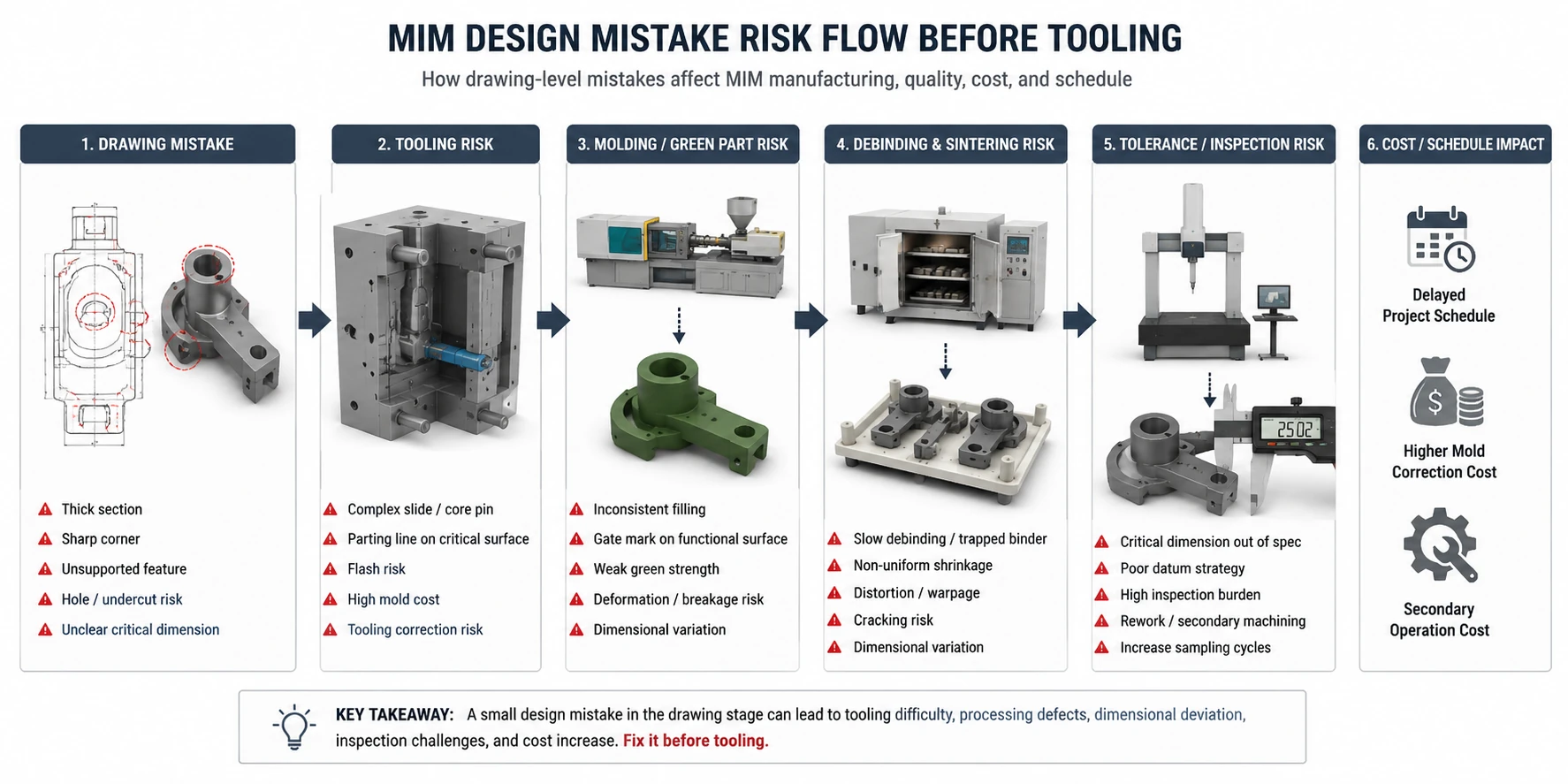
Start With the Highest-Risk MIM Design Mistakes
Before mold release, prioritize mistakes that can change tooling feasibility, sintering stability, or critical dimension control. These issues are usually harder and more expensive to correct after the mold is built, so review them before focusing on lower-risk drawing details.
Can the part be filled, released, ejected, and controlled without excessive mold complexity?
Can the part shrink and rest during sintering without unacceptable distortion or flatness loss?
Are tight tolerances applied only where they are functionally required?
When one issue becomes the main project risk, check the corresponding requirements for wall thickness, gate design, mold design, shrinkage compensation, or MIM tolerances before the mold design is frozen.
For a full pre-tooling review sequence, follow the MIM DFM review process and the MIM DFM design checklist.
Mistake Priority Map: From Design Error to Production Risk
Review these risks by their potential production impact. Start with issues that can change tooling feasibility, sintering stability, or critical dimension control; project-specific DFM decisions should still be based on the actual geometry, material, tolerance, and application requirements.
| Priority | Design Mistake Type | Main Production Risk | Review Before Tooling |
|---|---|---|---|
| High | Internal undercuts, blocked tooling direction, unsupported core pins | Complex slides, flash, mold cost, release risk | Mold opening direction, parting line, core pin support |
| High | Thick sections or sudden wall transitions | Non-uniform shrinkage, distortion, cracking, sink marks | Wall thickness, coring, rib design, transition radius |
| High | No sintering support surface for long spans or cantilevers | Warpage, flatness loss, dimensional drift | Setter contact surface, orientation, support strategy |
| High | Tight tolerances applied to all dimensions | High inspection cost, machining demand, sampling corrections | Critical dimensions, datum strategy, as-sintered vs machined features |
| Medium | Gate mark placed on a functional or cosmetic surface | Surface defect, sealing issue, assembly interference | Gate location, flow path, protected surface map |
| Medium | Material, heat treatment, or surface finish confirmed late | Property mismatch, cost change, process changes | Material grade, hardness, corrosion, magnetic or wear requirement |
| Medium | RFQ drawing lacks datums, application, annual volume, or inspection notes | Incomplete quotation, unclear manufacturability review | 2D/3D files, critical dimensions, application background |

Common MIM Design Mistakes and Practical Corrections
During pre-tooling review, evaluate each recurring design problem by its cause, production consequence, and correction path, then determine whether it requires a geometry change, tooling adjustment, process control, inspection planning, or secondary operation.
Mistake 1: Treating a CNC or Plastic Injection Drawing as MIM-Ready
A common mistake is sending a CNC prototype drawing or plastic injection molded part design directly for MIM quotation. CNC design often accepts sharp internal corners, deep machined pockets, and features that assume material is removed from a solid block. Plastic injection molding may also use design assumptions that do not fully reflect MIM green strength, debinding path, sintering shrinkage, or metal powder feedstock behavior.
The correction is to review the part as a MIM part, not only as a shape. Check whether the geometry can be filled with feedstock, released from the mold, handled as a green part, debound without trapped binder risk, supported during sintering, and inspected against real critical dimensions. For MIM-specific geometry and DFM limits, see MIM part design principles and metal injection molding design for complex precision parts.
Mistake 2: Designing Thick or Non-Uniform Wall Sections
Wall thickness variation is one of the most common sources of MIM risk. Thick sections can slow debinding, increase material usage, and create non-uniform shrinkage. Sudden transitions between thick and thin areas can also create stress concentration, sink marks, distortion, or cracking risk.
The correction is not always to make every area thin. The real goal is to make wall thickness more uniform where feasible, use coring or rib design where appropriate, and avoid abrupt section changes. For critical parts, thick zones should be reviewed together with gate location, debinding path, sintering orientation, and tolerance requirements. For wall-thickness limits and dimensional consequences, see the MIM wall thickness design guide and how part dimensions affect final MIM part quality.
Mistake 3: Using Abrupt Transitions, Sharp Corners, and Stress Concentration Features
Sharp internal corners and abrupt section transitions may look acceptable in CAD, but they often create manufacturing risk in MIM. During injection molding, flow may hesitate around abrupt geometry. During ejection and green part handling, fragile features may crack or deform. During sintering, stress concentration and uneven shrinkage may increase distortion risk.
The correction is to review radius, transition geometry, and feature location before tooling. Internal corners should be softened where function allows. Thin-to-thick transitions should be gradual. If a sharp edge is functionally required, it should be identified as a critical feature so the supplier can decide whether it should be molded, coined, machined, or otherwise controlled after sintering.
Mistake 4: Adding Holes, Slots, or Undercuts Without Tooling Direction Review
MIM can produce complex holes, slots, side features, and undercuts, but they still need mold direction review. A hole that cannot be supported properly may bend a core pin. A slot near a thin wall may create filling or ejection risk. An internal undercut may require slides, collapsible cores, machining after molding, or a design change.
The correction is to review each hole, slot, and undercut according to mold opening direction, core pin support, parting line feasibility, seal-off area, and flash risk. Internal undercuts should not be treated as “free complexity.” They may be justified for functional value, but they should be reviewed before the mold design is frozen. For tooling-direction and core-support limits, see MIM holes, slots, and undercuts and MIM mold design.
Mistake 5: Placing Gates, Parting Lines, or Ejector Marks on Critical Surfaces
Gate marks, parting line vestiges, ejector marks, and slide witness marks are not only cosmetic issues. If they are placed on sealing surfaces, datum surfaces, sliding contact areas, assembly interfaces, or visible cosmetic zones, they may affect function, inspection, or customer acceptance.
The correction is to define protected surfaces before tooling. A good MIM drawing should identify functional faces, cosmetic zones, datum surfaces, assembly contacts, and surfaces that cannot accept gate vestige or parting line mismatch. The supplier can then review gate location, flow path, parting line position, ejection strategy, and secondary finishing options. Read more about MIM gate design, mold design, and mold design quality risks in MIM.

Mistake 6: Ignoring Sintering Support Surfaces and Unsupported Features
MIM parts shrink during sintering, and the part must be supported in a way that protects shape, flatness, and critical dimensions. Long spans, thin arms, cantilevers, delicate points, and asymmetric mass distribution may distort if the design does not provide stable support areas.
The correction is to review the part’s sintering orientation early. Identify surfaces that can contact setters or supports without damaging functional or cosmetic requirements. If no acceptable support surface exists, the design may need small geometry changes, support pads, sacrificial surfaces, or a different orientation strategy. This is why sintering distortion control begins with geometry and support planning, not only with furnace settings. For setter contact, orientation, and distortion control, see MIM sintering supports and debinding and sintering quality risks.
Mistake 7: Assuming Shrinkage Is Uniform on Every Feature
A dangerous assumption is treating MIM shrinkage as one simple scale factor that applies equally to every feature. In reality, shrinkage control depends on material, feedstock, mold design, part geometry, wall thickness, sintering support, furnace conditions, and how dimensions are measured.
The correction is to identify critical dimensions and discuss shrinkage compensation before tooling. Some dimensions may be stable as-sintered. Others may need mold adjustment after first samples. A few highly critical features may require secondary machining. The key is to separate functional dimensions from non-critical dimensions instead of applying the same tolerance expectation everywhere. For shrinkage planning and dimensional capability, see MIM shrinkage compensation and MIM tolerances.
Mistake 8: Applying Tight Tolerances to Every Dimension
Over-tolerancing is one of the easiest ways to increase MIM project risk. If every dimension is marked as critical, the supplier cannot easily separate molded features, as-sintered features, machined features, and inspection reference features. This can increase sampling effort, inspection cost, mold correction cycles, and unnecessary secondary operations.
The correction is to classify dimensions into functional groups: critical-to-function, assembly-related, cosmetic, reference-only, and non-critical. Tight tolerances should be reserved for dimensions that truly affect function. Where a feature must be tighter than normal as-sintered capability, secondary machining, sizing, coining, or grinding may need to be reviewed. For tolerance allocation and inspection planning, use the MIM tolerance guide and the MIM tolerance and shrinkage checklist.
Mistake 9: Confirming Material, Heat Treatment, or Surface Finish Too Late
Material selection is not a final decoration step. In MIM, material grade, heat treatment, surface finish, corrosion requirement, magnetic performance, hardness, wear behavior, and biocompatibility requirements can affect shrinkage behavior, sintering cycle, secondary operations, inspection, and cost.
The correction is to confirm material and performance requirements before RFQ or at least before tooling. If the material is still open, the drawing should define application conditions: load, wear, corrosion, temperature, magnetic response, contact surface, and cosmetic expectations. The supplier can then review whether a standard MIM material is suitable or whether an alternative material family should be considered. Review the MIM materials guide and the article on material-related MIM quality risks.
Mistake 10: Sending RFQ Drawings Without Critical Dimensions, Datums, or Annual Volume
A MIM RFQ is not only a price request. It is also a manufacturability review. If the drawing does not identify critical dimensions, datums, protected surfaces, material requirements, surface finish, application, annual volume, and inspection expectations, the supplier may quote with assumptions that later become technical or commercial problems.
The correction is to send both 2D drawings and 3D CAD files where possible. Mark critical dimensions clearly. Separate as-sintered and post-machined requirements. Identify protected surfaces and acceptable mark areas. Provide expected annual volume because tooling strategy, cavity planning, sampling logic, and cost review depend on production quantity. Use the MIM DFM design checklist, request a quote, or contact XTMIM for drawing review.
Where to Review Each MIM Design Problem Next
Once a design risk is identified, use the corresponding guide below to review the relevant geometry, tooling, shrinkage, tolerance, or process-control requirements.
| If You Found This Problem | Review Next | Why |
|---|---|---|
| CNC or plastic injection drawing used without MIM-specific review | MIM Part Design | Recheck geometry, wall transitions, green-part handling, sintering behavior, and critical surfaces as MIM features. |
| Thick or uneven wall sections | Wall Thickness Design | Review wall uniformity, coring, ribs, and gradual transitions before tooling. |
| Holes, slots, or undercuts conflict with tooling direction | Holes, Slots and Undercuts | Check mold opening direction, core support, parting lines, slides, and flash risk. |
| Gate mark or parting line conflicts with a protected surface | Gate Design | Review flow path, acceptable mark zones, functional surfaces, and cosmetic requirements. |
| Long span, thin arm, or asymmetric feature lacks sintering support | Sintering Supports | Review setter contact, orientation, support surfaces, and distortion risk. |
| Shrinkage is being treated as one uniform scale factor | Shrinkage Compensation | Separate critical dimensions and review mold scaling, support conditions, and sample correction strategy. |
| Tight tolerance is applied across most or all dimensions | MIM Tolerances | Separate as-sintered, machined, datum, and truly critical dimensions. |
| Tooling or secondary-operation cost is rising because of design complexity | Design for Cost | Review geometry, mold complexity, machining, finishing, inspection, and annual volume together. |
| The drawing still has multiple unresolved manufacturability questions | DFM for MIM | Use a structured DFM review before mold release instead of resolving each issue after sampling. |
When a Design Mistake Requires Redesign, Machining, or Process Review
Not every MIM design mistake has the same solution. Some problems require CAD redesign. Some can be solved by mold strategy. Some should be controlled by secondary operations. Some may indicate that MIM is not the best manufacturing route for the part.

| Situation | Preferred Action | Engineering Reason |
|---|---|---|
| Thick section creates debinding and shrinkage risk | Redesign, coring, or wall transition review | Geometry is the root cause; machining later does not remove internal process risk. |
| Critical bore requires tighter accuracy than as-sintered capability | Consider secondary machining | Machining may be more stable than forcing the entire part into tight tolerance. |
| Internal undercut requires complex slides | Redesign or review tooling feasibility | Added tooling complexity may increase cost, flash risk, and mold maintenance. |
| Long unsupported span distorts during sintering | Add support surface or revise orientation strategy | Sintering distortion must be controlled through design and support planning. |
| Large simple part has low complexity and high material usage | Reconsider MIM suitability | PM, CNC, casting, stamping, or another route may be more economical than MIM. |
| Cosmetic surface cannot accept gate or parting line marks | Revise gate/parting line plan or add finishing | Surface requirements must be known before mold design. |
Process suitability note: MIM is usually strongest for small, complex, high-density metal parts where geometry consolidation, fine features, and production volume justify tooling. A large simple part with low complexity, high material usage, or very low annual demand may need a process comparison before committing to MIM tooling.
For cost-driven decisions, review MIM design for cost. If the part may not be suitable for MIM, use the MIM suitability checklist before committing to tooling.
Drawing Review Checklist Before MIM Tooling
Before releasing a MIM mold, review the drawing with the following checklist. This should happen before tooling, not after first samples, because late clarification can turn into mold assumptions, sample correction, inspection disagreement, or unnecessary secondary operation cost.

- Are critical dimensions clearly marked?
- Are datum references defined?
- Are protected surfaces identified?
- Are acceptable gate mark, parting line, and ejector mark areas defined?
- Are wall thickness transitions reviewed?
- Are holes, slots, and undercuts reviewed against mold direction?
- Are unsupported sintering areas identified?
- Are tolerances separated into as-sintered and machined requirements?
- Are material, heat treatment, and surface finish requirements confirmed?
- Is estimated annual volume provided?
- Is the application environment known?
- Are inspection methods or acceptance requirements defined for key features?
- Are secondary operation expectations stated before quotation?
Use the MIM DFM design checklist, the tolerance and shrinkage checklist, or submit your drawing for review before tooling release.
Representative MIM Design Scenarios
These scenarios combine common conditions encountered during pre-tooling review to show how multiple design decisions can interact during tooling, sintering, tolerance control, and surface acceptance.

Scenario 1: Small Bracket with Thick Bosses and Unsupported Arms
What problem occurred: A small precision bracket was designed from a CNC prototype. It included two thick bosses, thin arms, sharp internal transitions, and a flatness requirement across an unsupported span.
Why it happened: The original drawing was optimized for machining from solid stock, not for MIM feedstock flow, debinding, sintering shrinkage, or support during firing.
Underlying cause: The thick bosses affected shrinkage, the sharp transitions concentrated stress, and the thin arms had limited support during sintering. The flatness requirement was applied without reviewing setter contact surfaces.
Correction: The design was revised with more uniform wall transitions, improved radius design, reduced local mass, and an agreed support surface. Critical dimensions were separated from general dimensions.
Prevention: Review wall thickness, support surfaces, critical dimensions, and functional surfaces together before tooling.
Scenario 2: Miniature Housing with Gate Mark on a Functional Surface
What problem occurred: A miniature metal housing included a sealing surface, internal side features, and a cosmetic outside face. The initial gate and parting line concept placed visible marks near a functional contact area.
Why it happened: The RFQ drawing did not identify protected surfaces, acceptable mark zones, or assembly contact areas. The supplier could not clearly separate cosmetic surfaces from functional surfaces during early tool review.
Underlying cause: The part was feasible for MIM, but the drawing did not tell the tool designer which surfaces had to remain protected.
Correction: The drawing was updated with protected surface zones, acceptable gate mark areas, datum references, and inspection priorities.
Prevention: Every MIM RFQ should include surface function information, especially for sealing, sliding, visible, datum, and assembly-contact areas.
FAQs About Common MIM Design Mistakes
Can I use a CNC drawing directly for MIM production?
A CNC drawing can be used as a starting point, but it should not be treated as automatically MIM-ready. CNC designs often include features that are easy to machine but risky or expensive to mold, debind, sinter, or inspect. A MIM DFM review should check wall thickness, shrinkage, protected surfaces, tooling direction, tolerances, and secondary operation needs.
Are tight tolerances always a mistake in MIM?
No. Tight tolerances are not a mistake when they are functionally necessary and reviewed early. The mistake is applying tight tolerances to every dimension without separating critical features from non-critical features. Some dimensions may be suitable as-sintered, while others may need machining, sizing, coining, or inspection planning.
Can MIM design mistakes be corrected after tooling?
Some design mistakes can be corrected after tooling through mold adjustment, process tuning, or secondary machining, but corrections after mold release are usually more limited and more expensive than pre-tooling DFM changes. Geometry-driven risks such as severe thick-to-thin transitions, unsupported sintering spans, unrealistic tolerance stack-ups, or blocked tooling direction should be reviewed before tooling.
Which MIM design mistakes increase tooling cost the most?
Tooling cost usually increases when the part requires complex slides, weak or long core pins, difficult parting lines, internal undercuts, tight seal-off areas, or repeated mold correction after sampling. A pre-tooling review should check mold opening direction, holes and slots, protected surfaces, and critical dimensions before the mold design is frozen.
What information should I send for a MIM design review?
Send 2D drawings, 3D CAD files, material requirements, heat treatment needs, surface finish expectations, critical dimensions, datums, protected surfaces, inspection requirements, annual volume, and application background. These details help the supplier review manufacturability, tolerance strategy, tooling risk, and production feasibility.
Submit Your Drawing for MIM DFM Review
For parts with thin walls, thick sections, undercuts, small holes, cosmetic surfaces, sealing faces, tight tolerances, or unclear material requirements, send your drawing before tooling for MIM DFM review.
Please provide the following inputs when available:
- 2D drawing and 3D CAD file;
- material grade or performance requirement;
- critical dimensions, datum references, and tolerance requirements;
- surface finish expectations and protected cosmetic or functional surfaces;
- estimated annual volume and application background.
The XTMIM engineering team can review whether the design is suitable for MIM, which features may require redesign, where tooling risk may occur, how shrinkage and sintering support should be considered, and which tolerances may need secondary machining or special inspection before tooling, sampling, or production approval.
Standards and Technical References
Project-specific DFM should be checked alongside relevant industry references. MIMA Complex Designs with MIM discusses gate location, holes, slots, parting lines, mold complexity, and tooling-cost considerations for MIM components.
MPIF Standard 35-MIM covers common MIM material specifications, explanatory notes, and definitions. It is useful for material and performance discussions, but it does not define every project-specific design, tooling, or tolerance decision.
The EPMA introduction to Metal Injection Moulding provides useful process-boundary context: MIM is mainly suited to complex-shaped parts in higher quantities and may not be economical when conventional pressing and sintering can produce the part more efficiently. Process suitability should therefore be confirmed before committing to MIM tooling.