Share your drawing, material requirements, annual volume, tolerance needs, or application details. Our engineering team will review your MIM project and respond with technical feedback or a quotation.
Material selection affects MIM part quality because each alloy system changes how the part shrinks, densifies, holds dimensions, responds to finishing, and performs in service. In metal injection molding, the best material is not simply the grade with the highest datasheet strength, hardness, or corrosion resistance. It is the material that best matches the part …
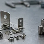
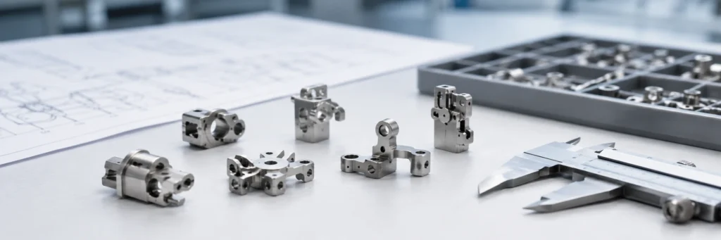
Material selection affects MIM part quality because each alloy system changes how the part shrinks, densifies, holds dimensions, responds to finishing, and performs in service. In metal injection molding, the best material is not simply the grade with the highest datasheet strength, hardness, or corrosion resistance. It is the material that best matches the part geometry, tolerance target, surface requirement, secondary operations, and production stability window. A material that works well for a compact component may create distortion, flatness drift, finishing inconsistency, or unnecessary process burden in a thin, flat, or highly detailed part. For this reason, material selection should be reviewed as an early quality-control decision, not only as an alloy choice.
Engineering Note: For readers who want standardized references behind MIM material selection, it is worth reviewing the MPIF Standards page, where Standard 35-MIM is described as covering the most common materials used in metal injection molding with explanatory notes and definitions. The 2025 edition release note also highlights continuing updates to MIM material standards, including titanium and stainless steel revisions. For broader technical study, MPIF’s PIM Tutorial and MIM conference resources continue to treat materials, binders, part design, debinding, and sintering as linked engineering decisions rather than isolated topics.
Material selection in metal injection molding is often discussed as if it only determines nominal properties such as strength, hardness, or corrosion resistance. In practice, that view is too narrow. The selected material also affects powder behavior, feedstock performance, debinding response, sintering shrinkage, feature stability, finishing response, and lot-to-lot repeatability. That is why the right material for a MIM part is not automatically the material with the highest datasheet values. It is the material that best supports the real quality target of the part across the full production route.
For engineering teams and buyers, the more useful question is not “Which alloy sounds best?” but “Which material gives this specific part the best chance of meeting dimensional, functional, and cosmetic requirements in stable production?” That shift in thinking matters. A material that looks ideal in theory may still create distortion risk, finish inconsistency, or unnecessary process burden once the geometry, tolerance level, and downstream operations are taken into account.
Material choice in MIM affects more than nominal properties. It influences shrinkage behavior, density development, surface quality, and production consistency across the full manufacturing route.
What “Part Quality” Really Means in MIM
In MIM, part quality should be reviewed as a combination of dimensional stability, mechanical consistency, surface condition, and functional reliability rather than as a single mechanical number. A part may pass a tensile requirement and still fail the real application if the hole position drifts after sintering, the flatness is unstable, the surface finish is inconsistent, or the finishing response is poor. Good MIM quality is multidimensional, and that is exactly why material selection deserves more attention early in the project.
The first dimension is dimensional quality. This includes shrinkage consistency, tolerance stability, flatness, feature accuracy, and resistance to warpage or distortion. For many MIM parts, especially small complex components, dimensional repeatability is one of the clearest signals of whether the process and material are truly matched.
The second dimension is mechanical quality. Density, strength, hardness, toughness, and wear resistance matter, but they matter in a controlled and repeatable way. A material that reaches the required hardness once in development but varies in production does not support real part quality.
The third dimension is surface quality. This covers as-sintered appearance, edge integrity, cosmetic consistency, and response to polishing, passivation, plating, or heat treatment. Many MIM parts are judged not only by function, but also by how stable the final surface looks and behaves after secondary operations.
The fourth dimension is functional reliability. This includes corrosion resistance, wear behavior, dimensional stability in service, and long-term performance under the real operating environment. A material can be processable in MIM and still be the wrong quality choice if it does not fit the application’s true service demands.
In MIM, part quality should be evaluated through dimensional stability, mechanical performance, surface condition, and functional reliability rather than by strength alone.
How Material Selection Changes MIM Part Quality
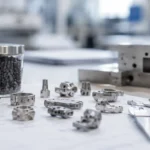
Material selection changes MIM part quality mainly through four linked mechanisms: shrinkage behavior, densification stability, service-property fit, and secondary finishing response. The most direct effect is shrinkage and dimensional stability. Different material systems do not behave identically during sintering. Even when the tooling concept is sound, the final dimensional result still depends on how the selected material densifies, shrinks, and responds to the thermal cycle. That is why changing material can alter flatness, feature position, and tolerance behavior even when the part design remains the same.
Material selection also affects density development and mechanical consistency. In engineering terms, the goal is not just to reach a target property once. The goal is to achieve the intended density and mechanical performance consistently in repeat production. Some materials offer a wider processing window for stable densification, while others demand tighter control or introduce more risk when the geometry is thin, flat, or highly detailed.
A third effect is on corrosion, wear, and service performance. Engineers often choose material based on the most visible requirement, such as corrosion resistance, but the real failure mode of the part may actually be wear, edge damage, local deformation, or dimensional instability in service. When that happens, the selected material solves the wrong problem.
Material selection also changes surface quality and secondary finishing response. Some materials are more forgiving in polishing, passivation, plating, or heat treatment. Others may introduce more risk of cosmetic inconsistency, edge instability, or post-treatment distortion. In practical terms, this means the best as-sintered material is not always the best finished-part material.
Material selection changes MIM quality through multiple linked outcomes, including dimensional stability, density consistency, service performance, and secondary finishing behavior.
Material Selection Quality Risk Table
The table below shows how material-selection decisions can turn into measurable MIM part quality risks. It is intended as an engineering review aid, not as a replacement for material standards, drawing review, or production validation.
Material Review Factor
Quality Risk It Can Influence
RFQ / Drawing Review Question
Shrinkage behavior
Flatness drift, tolerance variation, hole-position movement, and asymmetric distortion after sintering.
Is the geometry thin, flat, asymmetric, or tolerance-sensitive?
Densification window
Mechanical variation, density inconsistency, and unstable repeatability across production lots.
Does the selected material provide a stable sintering window for this part shape?
Corrosion / wear target
Wrong material priority, surface failure, local wear, or premature service issues.
Is the real failure mode corrosion, wear, deformation, or cosmetic change?
Secondary operations
Post-treatment distortion, finish inconsistency, edge instability, or excessive correction work.
Will polishing, passivation, plating, heat treatment, sizing, or machining be required?
Production robustness
Scrap risk, correction burden, and unstable lot-to-lot quality during repeat production.
Is the material suitable for repeat production, not only prototype validation?
Why the Same Part Design Can Behave Differently with Different Materials
One of the most useful lessons in MIM is that material choice cannot be evaluated in isolation from geometry, tolerance targets, and the expected finishing route. The same design can behave very differently when a different material is used because the relationship between material behavior and geometry is what drives many quality outcomes.
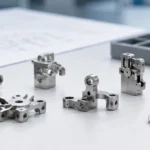
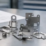
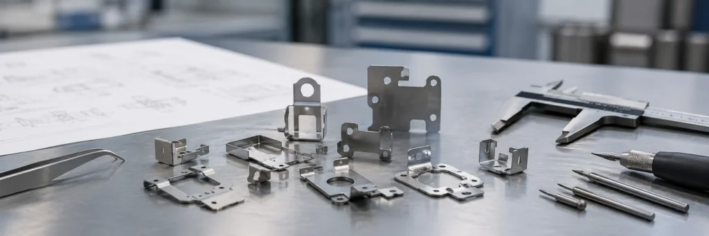
Thin walls and fine features are a good example. A material that performs well in a compact, balanced geometry may become less forgiving in a thin, distortion-sensitive design. A flat or elongated part can show more sensitivity to shrinkage behavior than a more compact shape. A part with local mass concentration or abrupt thickness transitions may respond differently again. In each case, the geometry changes how material behavior appears in the finished part.
A common engineering mistake is to assume that a material validated on one MIM component will behave similarly on another simply because the alloy family is the same. In practice, geometry can change the risk profile completely. A material may be acceptable for a dense compact bracket yet far less stable in a thin cover plate, fine-toothed component, or part with critical hole-position requirements.
Consider a simple example. A team chooses a material mainly because its datasheet suggests strong corrosion resistance and adequate strength. On a compact test coupon, the result looks fine. But on the real production part, which has a wide flat surface and a tight assembly fit, the part begins to drift in flatness after sintering. The issue is not that the material is bad. The issue is that the material behavior is not well matched to the geometry and dominant quality target of that specific design.
The same geometry can produce different quality results when the material changes, especially in thin walls, flat areas, critical holes, and distortion-sensitive features.
Common Material Selection Mistakes That Become Quality Problems
The first common mistake is choosing material by datasheet properties alone. Strength, hardness, and corrosion ratings are important, but they do not tell the full quality story in MIM. A material that looks ideal on paper may still create problems in shrinkage consistency, finishing response, or production yield.
The second mistake is ignoring the interaction between material and geometry. In MIM, geometry sensitivity matters. Thin walls, flat areas, fine edges, and dense local features all change how material behavior shows up in the final part. When geometry is not considered early, material-related quality issues often appear late, when changes are more expensive.
The third mistake is selecting for one visible property while missing the real failure mode. For example, a team may select a stainless grade because the part “needs corrosion resistance,” while the real long-term risk is wear, local deformation, or shape drift. Good material selection begins with the dominant quality problem, not with habit.
The fourth mistake is treating all MIM-capable materials as equally easy to control. Some materials are technically feasible, but that does not mean they are equally efficient, equally stable, or equally forgiving in mass production. Technical feasibility is not the same as production robustness.
Many MIM quality issues begin with early material-selection mistakes, such as choosing by datasheet alone or ignoring the interaction between geometry and material behavior.
How to Choose a MIM Material Based on the Real Quality Target
If dimensional control matters most, material selection should begin with shrinkage consistency, geometry compatibility, and tolerance risk. For broader material-family screening, engineers can also review XTMIM’s MIM materials overview and MIM material selection guide before freezing the final alloy direction. The key question is not only whether the material can be molded and sintered, but whether it can do so with stable shape control for the specific geometry.
If corrosion resistance matters most, the review should go beyond alloy name. The engineering team should consider the actual service environment, surface condition, required finish, and whether secondary processing may influence final performance. In many projects, corrosion is not just a base-material issue. It is also a finish and surface-integrity issue.
If strength or wear resistance matters most, the selected material should be judged against density target, post-sinter treatment route, and the balance between hardness and control risk. High property potential is useful only when it can be translated into stable part quality without creating excessive distortion, brittleness, or finishing burden.
If overall production stability matters most, the best material is often the one that provides the most reliable quality window, not the most impressive datasheet number. This includes scrap risk, dimensional correction burden, post-processing load, and consistency across lot-to-lot production. In real projects, total quality cost is often a better decision metric than raw material price alone.
The right MIM material should be selected according to the dominant quality target of the part, whether that target is dimensional control, corrosion resistance, wear performance, or production stability.
Common MIM Material Families and Their Quality Trade-Offs
Stainless steels are widely used in MIM because they can provide a useful combination of corrosion resistance, strength, and suitability for small complex parts. They are often a strong choice when corrosion behavior and general-purpose performance matter at the same time. For engineers who need a standardized property reference rather than a marketing summary, MPIF Standard 35-MIM remains one of the key external starting points.
Low-alloy steels can be attractive when strength-to-cost balance is important. Their value often lies in meeting performance targets efficiently, but they require a realistic view of corrosion limits and downstream processing needs.
Tool steels and hardenable steels make sense when wear resistance or hardness is the dominant requirement. The trade-off is that the project team must pay more attention to treatment route, edge stability, and the interaction between high property ambition and dimensional control.
Titanium and specialty alloys are best reserved for parts with clear functional justification, such as weight reduction, corrosion demand, or specialized performance requirements. They should not be selected simply because they sound more advanced. The most effective engineering choice is usually the most balanced one rather than the most exotic one.
Authority Reference: The MPIF 2025 edition notice for Standard 35-MIM specifically notes updates and new material standards, including titanium-related entries and stainless steel corrosion-related revisions. That is a useful reminder that material selection should be tied to recognized engineering references rather than simplified brochure claims.
A Practical Engineer’s Checklist Before Freezing the Material
Before locking in a MIM material, the engineering team should answer a few practical questions. What is the actual failure mode of the part? Is the main risk corrosion, wear, dimensional drift, surface damage, or strength loss? Which quality target is least negotiable? Does the geometry increase sensitivity to shrinkage or distortion? What secondary operations will be required? Can this material hold stable quality at production volume rather than only in development trials?
Checklist for Engineering Review
What is the real failure mode of the part in service?
Which quality target is least negotiable: dimensions, corrosion, wear, strength, or appearance?
Does the geometry increase shrinkage or distortion sensitivity?
Will polishing, passivation, plating, sizing, machining, or heat treatment be required?
Can the selected material deliver stable quality at production volume?
Does the material reduce total project risk rather than only raw material cost?
Before freezing a MIM material, engineering teams should review failure mode, geometry risk, secondary operations, production consistency, and total project risk.
Related MIM Part Quality Factors
Material selection is one part of a wider MIM quality-control system. For a complete review, it should be considered together with part design, feedstock behavior, mold design, injection molding stability, debinding, sintering, and final dimensional requirements.
Engineering review path: If material choice may affect dimensional stability, surface condition, or inspection planning, review the selected alloy together with the part drawing, tolerance targets, and inspection requirements. You can compare material options through XTMIM’s inspection and testing capability, or submit a drawing for a project-specific review.
In MIM, material selection is not just an alloy decision. It is an early quality decision that influences shrinkage behavior, dimensional repeatability, density development, surface response, finishing compatibility, and long-term production stability. The most effective MIM material is not the one with the highest nominal property on paper. It is the one that best matches the part’s dominant quality requirement, the geometry’s risk profile, and the realities of the full manufacturing route.
If you are evaluating a new MIM project, a more reliable material decision usually starts by asking three questions first: what quality target matters most, what geometry risk cannot be ignored, and what process burden is acceptable in production. That is the point where material selection begins to support real part quality instead of only theoretical performance. For new projects, XTMIM can review material direction together with geometry, tolerance, secondary operations, and RFQ requirements through drawing review or a structured RFQ request.