
MIM Bracket Parts for Compact Metal Assemblies
MIM bracket parts are compact metal components used to mount, locate, support, retain, or position another part inside a mechanical assembly. Typical candidates include compact frame, mounting, sensor, camera, optical, laptop, and support brackets with integrated three-dimensional features.
Start by confirming the bracket form, assembly function, size range, and geometry. Then review material, tolerances, holes, slots, bosses, ribs, secondary operations, and DFM risks.
Representative bracket forms: The real MIM bracket examples below show compact frame, mounting, support, sensor, and structural geometries before moving into DFM, material, tolerance, and process review.
- First priority: identify the real bracket part form, assembly function, and geometry features.
- Then review: custom features, material, tolerances, holes, slots, bosses, ribs, and DFM risks.
- Better suited elsewhere: simple sheet metal brackets, very large structural brackets, and low-volume prototypes may fit other processes better.
Real MIM Bracket Part Examples
The real parts below show representative MIM bracket forms used to evaluate geometry, assembly function, DFM risk, material choice, and tolerance strategy.
Together they cover compact device brackets, support-boss forms, sensor brackets, and a larger structural example that requires additional review of size, load, flatness, and process suitability.
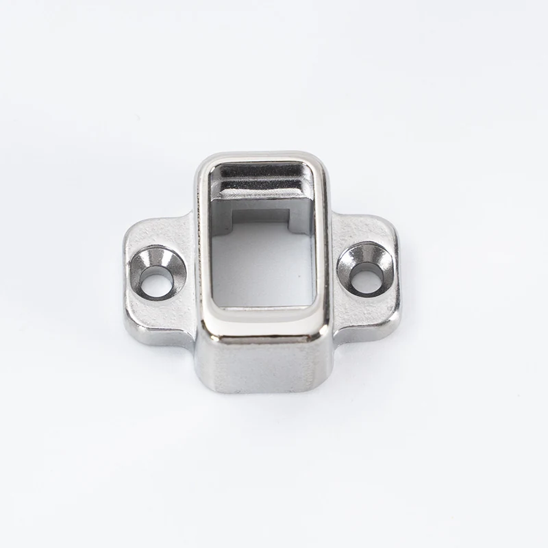
304 Stainless Steel Mobile Phone Bracket
Representative compact MIM bracket with frame geometry, side mounting holes, and integrated support features.
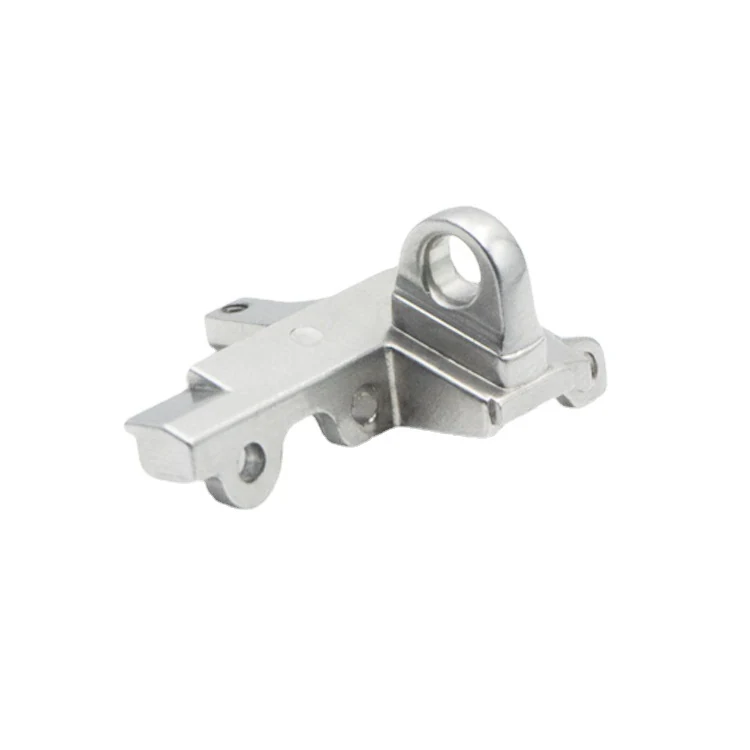
Laptop Computer Bracket
Shows bracket geometry with holes, raised mounting features, steps, arms, and local support areas that may need MIM DFM review.
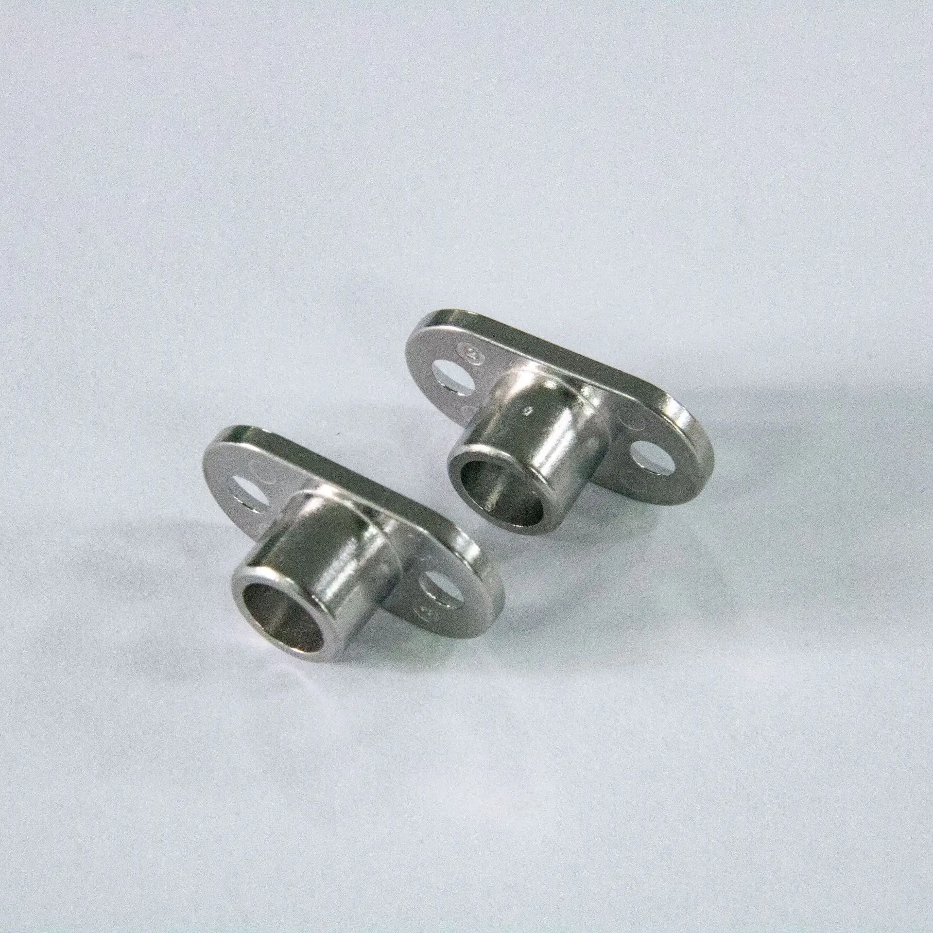
304 Stainless Steel Mobile Phone Bracket Accessory
Shows a compact device bracket accessory with integrated support bosses and mounting features.

Titanium New Energy Vehicle Sensor Bracket
Representative sensor bracket where compact support, mounting, and locating features define the bracket function.

Automotive Structural Bracket Part
Structural bracket parts require additional review of size, load, flatness, and process suitability before MIM is selected.
Quick Answer: Which Bracket Parts Make Sense for MIM?
A bracket part is a strong MIM candidate when it is small, compact, functionally integrated, and needed in production volume. Good candidates often combine mounting holes, locating tabs, support arms, bosses, ribs, slots, side features, or compact frame geometry in one metal part. MIM is less suitable for simple bent sheet metal brackets, large flat plates, very low-volume prototypes, or large structural brackets where stamping, machining, fabrication, casting, or another process is more practical.
Small Bracket Part Geometry
Use MIM when the bracket part has compact 3D geometry that would otherwise need multiple CNC operations, welded details, separate fasteners, or complex assembly.
Bracket Features Need Review
Hole direction, slot length, support arms, boss geometry, datum surfaces, wall transitions, and sintering support should be reviewed after the bracket part form is confirmed.
Simple Sheet Brackets
If the design is only a flat or bent sheet metal bracket with limited 3D complexity, stamping or sheet metal fabrication is usually more practical.
What Are MIM Bracket Parts?
MIM bracket parts are small metal components used to mount, support, locate, retain, or position another part inside a mechanical assembly.
They differ from simple sheet metal brackets when the design depends on three-dimensional features such as bosses, ribs, side holes, locating tabs, undercuts, curved profiles, thin walls, threaded areas, or integrated mounting interfaces.
From a manufacturing perspective, MIM uses fine metal powder mixed with binder to form feedstock, injection molds the green part, removes binder through debinding, and sinters the part to reach a dense metal component. Because sintering shrinkage is part of the process, bracket DFM must consider tooling compensation, green part handling, sintering support, datum selection, secondary machining needs, and final inspection before mold release.
Industrial Bracket Types
Miniature mounting brackets, sensor brackets, camera or optical brackets, locating brackets, ribbed support brackets, retainer brackets, locking brackets, U-shaped brackets, frame-style brackets, boss-integrated brackets and slotted bracket plates.
Dental Orthodontic Brackets
Orthodontic dental brackets should be reviewed under dental or medical MIM parts because their material, inspection, regulatory and functional requirements are different.
Simple Sheet Metal Brackets
If the bracket is only a folded sheet metal part with one or two holes, stamping or sheet metal forming is usually more practical than MIM.
For broader component categories beyond bracket geometry, visit MIM parts. The bracket guidance here focuses on bracket-specific geometry, process suitability, and DFM review.
When Are Bracket Parts Suitable for MIM?
Bracket parts are good candidates for MIM when complexity is concentrated in a small metal part and the production volume can justify tooling. In practice, MIM becomes more attractive when the bracket has geometry that would require multiple CNC setups, separate fasteners, small welded features, or difficult sheet metal forming.
| Bracket Feature | MIM Suitability | Engineering Reason |
|---|---|---|
| Small bracket with complex geometry | High | MIM can form compact 3D features that may be costly by CNC machining or multi-part assembly. |
| Multiple holes, slots, or side features | High | These features may be integrated into the molded geometry, but their direction and core feasibility still need review. |
| Integrated boss, standoff, or locating post | High | MIM can reduce welding, riveting, inserts, or separate fastened details when the boss design is controlled. |
| Thin-wall bracket with ribs or webs | Medium to high | Useful when ribs support stiffness without creating heavy sections, local sink, or sintering distortion. |
| Tight datum surfaces or critical hole positions | Needs review | Critical features may require secondary machining, controlled inspection, or revised datum strategy. |
| Long unsupported arm or cantilever | Risky | Green part handling, debinding support and sintering distortion must be evaluated before tooling. |
| Large flat plate bracket | Low | Flatness, support marks, size, and economics may make MIM less suitable than fabrication, casting, or machining. |
| Simple bent sheet metal L-bracket | Low | Stamping or sheet metal forming is usually more economical when no 3D complexity is required. |
For early process selection, bracket projects can also be compared with MIM vs CNC machining when the design is still moving between prototype validation and production tooling.
Common MIM Bracket Part Types
The bracket types below are grouped by structural form and integrated geometry. Use them to identify how features such as bosses, ribs, slots, frames, side holes, and support arms affect MIM suitability and DFM.
Miniature Mounting Brackets
Suitable when: the bracket is compact, has multiple small features, and would require several CNC operations or complex secondary assembly.
MIM value: MIM can form the bracket close to final shape and reduce the need for separate welded, riveted, or machined features.
DFM review point: hole direction, wall thickness transition, gate location, ejection area, and sintering support should be checked before tooling.
Not ideal when: the bracket is a simple folded metal part with one or two holes and no three-dimensional complexity.
Sensor, Camera and Optical Brackets
Suitable when: the bracket must hold a compact sensor, camera module, optical feature, or small device element in a repeatable position and the geometry is too complex for simple stamping.
MIM value: MIM can integrate sensor location, mounting, and structural support into one small metal part.
DFM review point: alignment surfaces, datum faces, critical hole positions, surface finish areas and post-machining needs must be clearly identified on the drawing.
Part classification: if the component primarily supports or locates a sensor, camera, or optical module, it fits this bracket category. If the sensor hardware itself defines the component’s main function, it should be evaluated as a different MIM part family.
Locating Brackets
Suitable when: the bracket has compact geometry and combines mounting and positioning features in one part.
MIM value: MIM can form small locating details near-net-shape, reducing separate machined blocks or assembled positioning parts.
DFM review point: critical datum surfaces should be separated from non-critical surfaces in the drawing so inspection and secondary machining can be evaluated correctly.
Not ideal when: the locating function requires extremely tight flatness or parallelism across a large surface without secondary machining.
Support Brackets with Ribs or Webs
Suitable when: ribs support the load path without creating thick mass areas or unbalanced shrinkage zones.
MIM value: MIM can integrate ribbed reinforcement into complex bracket geometry more easily than machining or stamping.
DFM review point: rib thickness, rib height, transition radius, nearby wall section, and expected support orientation should be reviewed together.
Not ideal when: ribs are too thick, unevenly distributed, or create heavy sections that may increase distortion risk.
Retainer Brackets
Suitable when: the retainer function requires a small metal part with multiple interacting surfaces or compact three-dimensional geometry.
MIM value: MIM can form retaining features that would be difficult to machine economically in high volumes.
DFM review point: retaining tabs and thin arms should be reviewed for green part handling, debinding, sintering distortion, and assembly stress.
Not ideal when: the retainer requires spring-like deflection beyond what the selected MIM material and geometry can safely support without validation.
Locking Brackets
Suitable when: the locking feature is small, integrated, and part of a compact mechanical assembly.
MIM value: MIM can integrate locking tabs, stops, small engagement faces, and support geometry into one part.
DFM review point: load direction, contact surfaces, wear areas, and validation requirements must be reviewed before tooling.
Not ideal when: the part is safety-critical, high-impact, or load-bearing without a defined test and validation plan.
Brackets with Integrated Bosses or Standoffs
Suitable when: the bracket includes screw bosses, standoffs, locating posts, raised mounting pads, or compact cylindrical features.
MIM value: MIM can reduce part count and improve repeatability by forming these features as part of the base bracket.
DFM review point: boss thickness, core pin strength, thread strategy, transition radius, and local shrinkage risk must be reviewed.
Not ideal when: the boss is very thick, isolated from surrounding walls, or requires a thread tolerance that must be post-machined but the design does not allow machining access.
Brackets with Holes, Slots and Side Features
Suitable when: holes and slots are positioned in mold-friendly directions and support the bracket’s function.
MIM value: MIM can integrate hole and slot geometry without multiple machining operations when the tooling direction is reasonable.
DFM review point: hole direction, core pin strength, slot length, edge distance, and relationship to datum features should be checked before tooling.
Not ideal when: long narrow slots or side holes create weak tooling conditions, high distortion risk, or impossible demolding directions.
U-Shaped, Frame-Style and Integrated Bracket Plates
Suitable when: the bracket includes functional 3D geometry, a frame-like support path, U-shaped positioning geometry, or a plate base that replaces multiple assembled or machined parts.
MIM value: MIM can combine a thin base, mounting structure, support ribs, side features and locating features into one compact part.
DFM review point: flatness expectation, sintering support, wall uniformity, long-side distortion risk, support marks and critical surface zones should be reviewed.
Not ideal when: the part is only a large flat plate, simple two-hole plate, or sheet metal mounting plate.
Stainless Steel MIM Bracket Parts
Suitable when: the environment, appearance, strength, and corrosion requirements justify stainless steel or another MIM material family.
MIM value: MIM can combine stainless steel material selection with complex bracket geometry.
DFM review point: material selection should be reviewed together with load, surface finishing, heat treatment, corrosion exposure, tolerance, and cost targets.
Material selection: for alloy choices beyond stainless steel, continue to the material section below and review corrosion, strength, heat treatment, finishing, tolerance, and cost requirements together.
Typical Applications for MIM Bracket Parts
These applications are grouped by function rather than geometry. They show where a bracket may be used and which application-specific DFM checks matter most.
Connector Support Brackets
Connector support brackets fix, align, retain, or support a compact connector assembly. They are most relevant when alignment, mounting, shielding, or retention features must be integrated into a small metal part.
- Typical forms: connector fixing brackets, terminal support brackets, shield support brackets, compact retaining frames.
- MIM value: integrated ribs, bosses, small holes, side features and compact support geometry.
- DFM focus: hole position, thin wall transition, assembly clearance, contact surface zoning and post-machining needs.
Hinge Support and Pivot-Area Brackets
Hinge-support brackets carry or locate pivot-related features within a compact assembly, especially when the surrounding geometry includes integrated bosses, holes, ribs, or reinforcement.
- Typical forms: hinge mounting brackets, pivot support plates, rotating assembly supports, laptop or wearable hinge-side brackets.
- MIM value: compact metal geometry around pivot areas, integrated bosses, holes and reinforced ribs.
- DFM focus: pivot-hole accuracy, load direction, wear surfaces, datum stability and possible secondary machining.
Sensor, Camera and Optical Mounting Brackets
Sensor and optical mounting examples are appropriate when the bracket’s main job is to locate, support, or retain a compact module in a stable position.
- Typical forms: sensor retaining brackets, camera support brackets, optical module holders, locating frames.
- MIM value: stable positioning geometry, small holes, datum surfaces, ribs and integrated support features.
- DFM focus: datum surfaces, alignment holes, cosmetic zones, finishing route and inspection method.
Compact Brackets with Tight-Feature Zones
Some compact brackets combine thin walls, ribs, slots, bosses, and precision locating features in a small area. These designs may suit MIM when near-net-shape geometry is combined with selected secondary operations for critical features.
- Typical forms: thin-wall support brackets, ribbed brackets, slotted brackets, boss-integrated brackets, precision locating brackets.
- MIM value: near-net-shape production of compact bracket geometry with selected secondary operations where needed.
- DFM focus: tolerance zoning, hole-to-hole relationship, flatness expectation, sintering support and inspection planning.
Application fit should be reviewed together with bracket geometry, load path, tolerance zones, material, secondary operations, and inspection requirements.
MIM Bracket Parts vs CNC, Stamping, Die Casting and PM
The real decision is not “MIM or not MIM.” The better question is which process matches the bracket geometry, volume, material, tolerance, and validation requirement. MIM is a strong candidate when a small bracket needs integrated 3D geometry. CNC may be better for prototype validation, stamping for simple sheet forms, die casting for larger alloy parts, and PM pressing for regular shapes that can be compacted vertically.
| Manufacturing Route | Better For | Not Ideal For | Bracket Decision |
|---|---|---|---|
| MIM | Small, complex, high-volume metal brackets with holes, ribs, bosses, slots, side features, and integrated support geometry. | Large brackets, low-volume prototypes, simple flat or bent parts. | Best when complexity and volume justify tooling and sintering shrinkage can be controlled. |
| CNC machining | Prototypes, low-volume parts, tight local features, early design validation. | High-volume complex small brackets with heavy material removal. | Useful before MIM tooling or for post-machined critical features. |
| Stamping / sheet metal | Simple L-brackets, bent plates, flat metal supports, low-cost thin sheet designs. | Thick bosses, 3D shapes, multi-axis holes, compact complex geometries. | Often better for simple bracket forms. |
| Die casting | Larger complex metal parts with suitable alloy and size range. | Very small fine features, high-density steel parts, tight local details. | Consider when size and alloy fit die casting better. |
| PM pressing | Regular shapes that can be compacted vertically. | Side features, undercuts, complex bracket geometry, multi-direction holes. | Better for simpler pressable geometries, not compact 3D bracket details. |
| MIM + secondary machining | MIM base geometry plus local precision holes, faces, or threads. | Designs that require every surface to be precision-machined. | Good hybrid route for complex brackets with selected critical features. |
In production, MIM bracket projects often fail not because the overall bracket shape is impossible, but because one or two critical features were not reviewed correctly: a long slot near a thin arm, a thick boss with no coring strategy, a datum face placed on a sintering contact surface, or a thread requirement assumed to be molded without confirming the tolerance need.
DFM Risks in MIM Bracket Parts
Bracket DFM review should focus on the features that control assembly, load transfer, molding, green part handling, debinding, sintering, and inspection. A bracket is usually not a decorative shape; it is an assembly function carrier.
For a deeper pre-tooling review of ribs, bosses, mounting datums, and sintering stability, see the MIM bracket design review.
| DFM Risk | Why It Happens | What to Review Before Tooling |
|---|---|---|
| Hole deformation | Core pin design, shrinkage, hole direction, and nearby wall thickness influence final hole geometry. | Hole size, hole direction, hole spacing, datum relationship, and whether the hole is molded or finished after sintering. |
| Slot warpage | Long slots reduce local stiffness and may create uneven shrinkage or weak support during sintering. | Slot length, slot width, surrounding wall thickness, rib layout, and support orientation. |
| Rib-related distortion | Ribs that are too thick, uneven, or poorly connected can create mass imbalance and local distortion. | Rib thickness, rib layout, transition radius, wall ratio, and load path. |
| Boss sink or distortion | Local mass concentration creates uneven shrinkage, especially near screw bosses and standoffs. | Boss wall thickness, coring strategy, thread plan, fillet design, and adjacent wall section. |
| Wall thickness transition | Abrupt thick-to-thin changes affect feedstock filling, debinding behavior, and sintering shrinkage. | Uniformity, transition radius, flow path, local mass balance, and gate location. |
| Sintering distortion | Long arms, unsupported spans, unbalanced sections, or poor support orientation may move during thermal processing. | Sintering support face, part orientation, center of gravity, and whether support marks affect critical surfaces. |
| Datum instability | Critical references can be affected by shrinkage, support marks, gate location, or secondary operations. | Datum zoning, inspection method, post-machining need, and relationship to mating parts. |
| Thread uncertainty | Molded thread, tapped thread, machined thread, or insert strategy may not be confirmed early enough. | Thread type, tolerance, torque, wall thickness, secondary operation, and inspection method. |
| Cosmetic surface issue | Gate marks, parting lines, ejector marks, or support contact may fall on visible or functional surfaces. | Functional vs cosmetic surface zoning, acceptable marks, and finishing requirement. |
| Load validation gap | Bracket function includes support, retaining, or locking behavior without a defined test plan. | Load direction, contact stress, vibration, wear, assembly method, and application-level validation. |
The following representative engineering scenarios illustrate common bracket DFM risks. They are examples for design review, not customer case studies.
Representative Engineering Scenario: Boss and Mounting-Hole Risk
What problem occurred: A compact mounting bracket had an integrated screw boss near the center of the part. During design review, the geometry showed risk of cracking or dimensional instability around the boss and adjacent hole.
Why it happened: The boss was much thicker than nearby walls, and the transition into the bracket base was abrupt. The hole was treated as a simple molded feature, but it also controlled assembly position.
Root cause: The issue was not only boss strength. The risk came from the combination of local mass concentration, unclear thread strategy, insufficient transition radius, and missing datum definition.
Recommended engineering response: Control the boss wall section, improve the transition geometry, and review the critical hole for post-sintering finishing when the tolerance or assembly function requires it.
How to prevent recurrence: Review integrated bosses together with wall thickness, hole function, thread requirement, core pin feasibility and inspection method before tooling release.
Representative Engineering Scenario: Long-Slot Warpage in a Thin Support Bracket
What problem occurred: A thin support bracket included a long slot close to one edge. The slot created a high risk of distortion and weak local stiffness during sintering.
Why it happened: The slot removed material from an already thin section and created uneven stiffness across the bracket. The surrounding rib layout did not support the load path.
Root cause: The problem is not simply slot length. The risk comes from the combination of thin wall, a long unsupported opening, uneven rib placement, and unclear support orientation.
Recommended engineering response: Review whether the slot can be shortened or redistributed, reposition ribs where needed, and check sintering support and datum stability before tooling.
How to prevent recurrence: Long slots should be reviewed with surrounding wall thickness, rib design, load path and sintering support before mold design begins.
Material Options for MIM Bracket Parts
Material selection for MIM bracket parts should begin with function, not material name. The same bracket geometry may need different material choices depending on load, corrosion exposure, wear, magnetic behavior, surface condition, heat treatment, and cost target.
| Material Direction | Suitable Bracket Use | Review Point |
|---|---|---|
| Stainless steel | Corrosion resistance, clean surface condition, visible or exposed brackets. | Confirm corrosion environment, surface finish, strength requirement, and whether passivation or polishing is needed. |
| Low alloy steel | Structural support, load-bearing function, heat treatment potential. | Review strength, heat treatment, dimensional stability, and post-sintering inspection needs. |
| Wear-resistant material | Contact or sliding areas in compact bracket features. | Confirm contact stress, wear surface, finishing route, and whether the bracket is acting as a bearing or guide surface. |
| Soft magnetic material | Brackets that also perform magnetic function. | Use only when magnetic performance is part of the functional requirement, not as a generic bracket material. |
| Special alloy | Special temperature, corrosion, or mechanical environment. | Review cost, material availability, sintering behavior, validation requirement, and supplier feasibility before design freeze. |
For material-driven projects, bracket geometry is only the starting point. Continue detailed alloy selection through MIM materials, MIM stainless steel parts, or MIM low alloy steel parts, depending on the required material direction.
Tolerance, Holes and Datum Review for MIM Brackets
Tolerance review for MIM bracket parts should be based on the bracket’s functional features. A drawing with every dimension marked as tight can increase cost and create avoidable production risk.
Critical Holes
Critical holes should be separated from clearance holes. If a hole controls alignment, rotation, or mounting position, it may require tighter inspection or secondary finishing after sintering.
Mounting Positions
Mounting holes should be reviewed together with the mating part, screw direction, assembly clearance, and load path. Hole-to-hole relationship may be more important than individual hole size.
Datum Surfaces
Datum surfaces should be selected based on actual assembly function. If a datum surface is also a sintering support surface or cosmetic face, the design team should review whether that creates conflict.
Flatness and Parallelism
Flatness and parallelism requirements should be used carefully on MIM bracket parts, especially for plate-like surfaces, long arms, or thin sections.
Molded vs Machined Features
The correct strategy may be a near-net-shape MIM bracket with selected post-machined holes, threads, or datum faces. This keeps the main geometry economical while controlling the features that affect assembly.
Inspection Planning
The drawing should define which dimensions are critical to function, which are reference dimensions, which surfaces are cosmetic, and which features must be inspected during production approval.
If your bracket requires local precision features, review whether the part should use MIM base geometry with secondary machining for critical holes, threads or datum surfaces. For geometry-driven tolerance decisions, see high precision MIM parts.
When MIM Is Not Suitable for Bracket Parts
MIM should not be selected simply because a part is small or metal. It is most useful when compact complexity, material performance, and production volume justify tooling. The following bracket types usually need another process or additional validation before MIM should be considered.
A practical rule: if the bracket can be made as a simple stamped or bent sheet metal component without losing function, MIM may not be the most economical route. If the bracket requires integrated geometry, compact metal features, and repeatable production, MIM becomes more reasonable.
What to Provide for a MIM Bracket DFM Review
A drawing-based review helps confirm whether the bracket is suitable for MIM before tooling investment. For bracket parts, the most useful inquiry is not only a general RFQ, but a manufacturing review package.
| Information to Provide | Why It Matters |
|---|---|
| 2D drawing with tolerances | Identifies critical dimensions, holes, datums, surface zones, and inspection needs. |
| 3D CAD file | Allows geometry, wall thickness, draft, parting direction, and tooling feasibility review. |
| Material requirement | Supports material family, heat treatment, corrosion, strength, and sintering route discussion. |
| Estimated annual volume | Helps determine whether MIM tooling is economically reasonable compared with CNC or stamping. |
| Application environment | Supports corrosion, wear, heat, surface finish, and validation review. |
| Load direction or support function | Helps evaluate bracket strength, retaining behavior, contact stress, and validation needs. |
| Critical holes and datum surfaces | Controls assembly, inspection planning, and secondary machining decisions. |
| Thread or insert requirement | Determines molded, tapped, machined, or insert strategy. |
| Surface finish requirement | Separates cosmetic surfaces, functional contact surfaces, gate areas, and support marks. |
| Prototype or production target | Helps decide CNC prototype, MIM tooling, pilot production, or phased development. |
Send Your Bracket Drawing for MIM Suitability Review
If your bracket part includes compact geometry, mounting holes, locating features, ribs, bosses, slots, side features, threaded holes, or integrated support structures, send your 2D drawing, 3D CAD file, material requirement, critical tolerances, surface finish requirement, estimated annual volume, and application background for review.
- Evaluate whether the bracket geometry is suitable for MIM.
- Review holes, slots, bosses, ribs, datum surfaces and thread strategy.
- Check whether key features should be molded or post-machined.
- Compare MIM with CNC, stamping, die casting or PM if needed.
- Identify DFM risks that should be resolved before tooling or trial production.
FAQ About MIM Bracket Parts
Are MIM bracket parts suitable for high-volume production?
Yes. MIM bracket parts are suitable when the bracket is small, complex, and needed in enough volume to justify tooling. If the bracket has multiple holes, bosses, ribs, slots, or integrated locating features, MIM may reduce machining and assembly work. For low-volume prototypes, CNC machining is usually more practical before MIM tooling.
What bracket features are best suited for MIM?
MIM is best suited for compact bracket features such as integrated bosses, standoffs, ribs, web structures, locating tabs, retaining features, holes, slots, side features, and complex three-dimensional profiles.
Can MIM produce holes, slots and bosses in bracket parts?
Yes. MIM can produce holes, slots, and bosses in many bracket parts, but the design must be reviewed for tooling direction, core pin strength, wall thickness, shrinkage, and sintering distortion.
Can MIM brackets have threaded holes?
MIM brackets can include threaded features, but the thread strategy must be confirmed before tooling. Depending on thread size, tolerance, torque, wall thickness, and production needs, the thread may be molded, tapped after sintering, machined, or supported by an insert strategy.
When should a bracket be made by CNC instead of MIM?
CNC machining is usually better for prototypes, low-volume production, early design validation, or brackets with very tight local features that are not yet stable enough for tooling.
When is sheet metal stamping better than MIM for brackets?
Sheet metal stamping is usually better for simple bent brackets, flat mounting plates, L-brackets, and thin sheet structures with low three-dimensional complexity.
Are these MIM brackets the same as orthodontic dental brackets?
No. The brackets covered here are industrial MIM parts used for mounting, locating, retaining, supporting, and positioning applications. Orthodontic dental brackets require a different review path because their design, material, inspection, and regulatory requirements are different.
What information is needed for a custom MIM bracket quote?
A useful RFQ should include a 2D drawing, 3D CAD file, material requirement, estimated annual volume, critical tolerances, application environment, load direction, thread requirements, surface finishing requirements, and target production stage.
Standards and Technical References Note
MIM bracket evaluation should combine supplier-specific DFM review with relevant MIM process and material references. These references support engineering discussion, but they do not replace project-level drawing review, material data confirmation, or formal customer specifications.
- EPMA Metal Injection Moulding overview: useful for process positioning, including the role of MIM for complex-shaped parts in production quantities.
- MPIF Standard 35-MIM information via MIMA: useful as a material standards reference for metal injection molded parts. Project-specific material selection should still consider geometry, heat treatment, surface finish, tolerance, and application environment.
- MPIF: useful as an industry association reference for powder metallurgy and related metal powder processing technologies.