
MIM Case Studies | Engineering Review Examples
This MIM case study library helps engineers and sourcing teams decide whether a small, complex metal part is worth evaluating for metal injection molding before tooling or RFQ. Start with the engineering problem—not the industry name: process conversion, geometry, material performance, or dimensional control. The examples on this page are clearly labelled educational composite scenarios unless a case is explicitly identified as a published production reference. Use them to compare your part with common MIM decision points, identify the risks that need review, and prepare the information required for a drawing-based manufacturability assessment.
Find a MIM Case by Engineering Challenge
Industry context can be useful, but MIM suitability is usually decided by the manufacturing problem. A medical, robotics, automotive, or electronics part may still be better suited to CNC machining, stamping, die casting, PM, or another process. Choose the case direction below that matches the decision you need to make.
Process Conversion
Best for: CNC, PM, die casting, stamping, or metal 3D printing comparisons.
Key question: Can MIM reduce process complexity without creating excessive tooling or secondary-machining cost?
CNC to MIMRoute SelectionDesign & Geometry
Best for: Thin walls, holes, slots, undercuts, long flats, and asymmetric parts.
Key question: Can the geometry be molded, handled, debound, sintered, and measured consistently?
DFMDistortion RiskMaterial Performance
Best for: Corrosion, strength, hardness, wear, heat treatment, or magnetic requirements.
Key question: Does the required material and post-treatment route fit the application and MIM process?
316L17-4PHTolerance & Inspection
Best for: Critical dimensions, functional surfaces, datum strategy, sizing, and machining.
Key question: Which features can remain as-sintered, and which need secondary control or inspection?
ToleranceInspectionApplication Context
Best for: Teams looking for familiar MIM applications in medical, robotics, electronics, automotive, and industrial products.
Key question: Does the application impose special performance, finish, validation, or quality requirements?
ApplicationsIndustry ContextCase Studies Are a Screening Tool, Not a Final DFM Decision
A similar case can help you identify likely risks, but final MIM suitability depends on the actual drawing, part size, material, critical dimensions, annual volume, secondary operations, and application requirements. Use the MIM design guide for technical background or request a drawing-based engineering review for a project-specific decision.
Educational MIM Engineering Scenarios
These composite scenarios are based on recurring MIM engineering decisions and are provided for technical education. They are not presented as named customer success stories. Start with the scenario closest to your current manufacturing problem, then continue to the detailed decision table in the matching section.
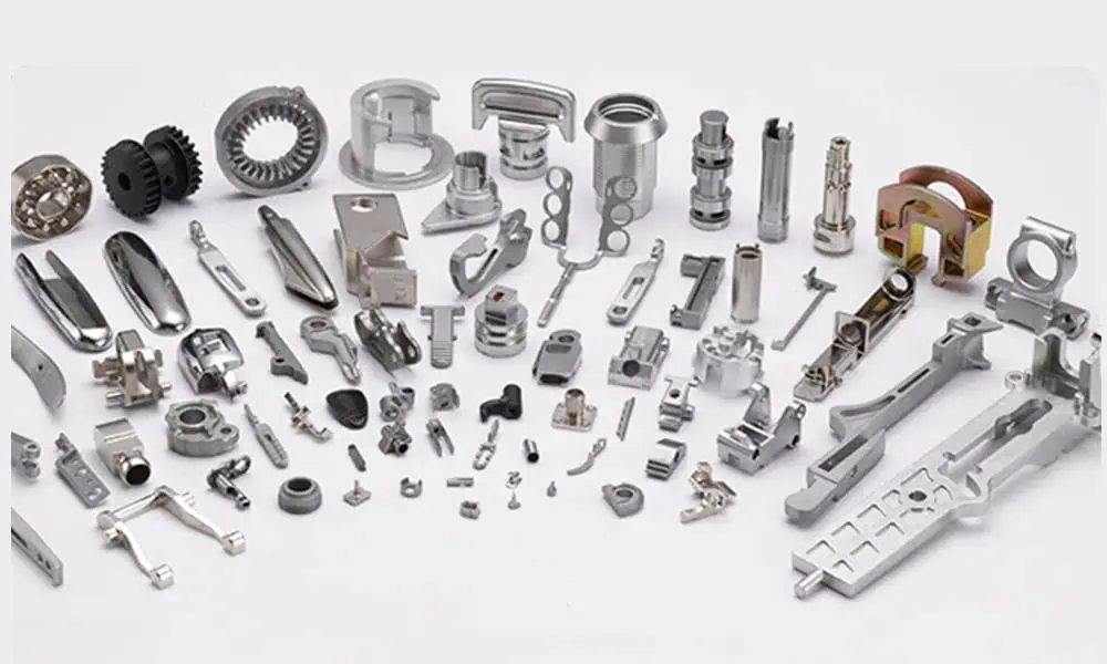
CNC to MIM Conversion
A small stainless steel bracket has rising machining time and fixture complexity as production volume increases.
Review focus: annual volume, tooling investment, near-net-shape opportunity, datum surfaces, and post-sintering machining.
Thin-Wall Distortion Risk
A compact part contains thin, unsupported, or unbalanced features that may distort during debinding and sintering.
Review focus: wall transitions, mass balance, gate strategy, sintering support, and realistic tolerances.
316L Material Selection
A corrosion-resistant part is specified only as “stainless steel,” without enough application or surface information.
Review focus: exposure environment, material grade, finishing, functional surfaces, and inspection criteria.
Critical Dimension Control
A compact MIM bracket contains multiple functional surfaces, but the drawing does not distinguish critical dimensions from general dimensions.
Review focus: datum strategy, as-sintered capability, sizing or machining, and inspection priority.
Process Selection & Conversion Cases
A conversion decision is not simply “Is MIM cheaper?” The useful question is whether MIM can produce the required geometry and material performance at the expected volume while reducing machining, assembly, or process complexity enough to justify tooling.
| Original Route | When MIM Is Worth Reviewing | Main Conversion Risk | Decision Check |
|---|---|---|---|
| CNC machining | Small complex part, repeated demand, high material removal, difficult fixtures. | Critical surfaces may still need machining after sintering. | Compare tooling, annual volume, removed machining steps, and secondary machining. |
| Die casting | Fine features, small geometry, or material requirements are difficult for the current casting route. | MIM may not match all casting economics or part-size expectations. | Review alloy, part size, feature detail, and production volume. |
| Stamping | The part needs 3D geometry, bosses, holes, or integrated features that are difficult to stamp. | Simple thin flat parts may remain better suited to stamping. | Compare geometry complexity, assembly steps, and functional requirements. |
| PM compaction | The part needs higher geometric freedom, density, or features not suited to axial pressing. | PM may remain more economical for simple high-volume shapes. | Compare pressing direction, density, geometry, and cost. |
| Metal 3D printing | A successful prototype is moving toward repeated production volume. | Tooling and MIM-specific design changes may be required. | Compare volume, surface requirements, tooling payback, and post-processing. |
Educational Scenario: CNC to MIM Conversion
- Scenario: A small stainless steel bracket is machined from bar stock and includes multiple holes, curved surfaces, and several setup-dependent features.
- Why MIM may be considered: Repeated production increases machining time, material removal, and fixture complexity, while some geometry may be formed near-net-shape.
- Main engineering risk: MIM does not automatically eliminate machining. Critical datum surfaces or tight functional dimensions may still require post-sintering operations.
- What to review: Annual volume, tooling investment, feedstock, shrinkage compensation, datum strategy, and secondary machining.
- Decision takeaway: MIM becomes more attractive when near-net-shape production removes enough machining or assembly work to justify tooling without shifting excessive cost into secondary operations.
For a deeper route comparison, see MIM vs CNC machining.
Design & Geometry Challenge Cases
In MIM, a shape is not proven manufacturable just because it can be molded. The geometry must also survive green-part handling, debinding, sintering shrinkage, support, measurement, and assembly.

| Geometry Feature | Why It Matters in MIM | Review Question |
|---|---|---|
| Thin walls | May increase filling, handling, and sintering distortion risk. | Is wall thickness consistent and adequately supported? |
| Small holes and slots | Tooling, shrinkage, flow, and inspection access may affect capability. | Which openings are function-critical, and what tolerance is actually required? |
| Undercuts | May add mold actions, ejection risk, and tooling complexity. | Can the feature be molded reliably, simplified, or moved to a secondary operation? |
| Long flat surfaces | May be sensitive to warpage during sintering. | Is a sintering support or geometry-balancing strategy required? |
| Sharp transitions | Can create local flow, stress, or shrinkage differences. | Can transitions be radiused or mass distribution improved? |
| Functional surfaces | May need tighter control than the surrounding geometry. | Can they remain as-sintered, or do they need sizing, machining, or dedicated inspection? |
Educational Scenario: Thin-Wall Distortion Review
- Scenario: A compact component contains a thin unsupported region and uneven mass distribution across the part.
- Why MIM may be considered: The geometry is difficult to machine efficiently and could benefit from near-net-shape forming.
- Main engineering risk: Wall-thickness variation, unsupported features, gate location, and sintering support can create non-uniform shrinkage or distortion.
- What to review: Wall transitions, mass balance, feature position, support method, gate strategy, and which dimensions are genuinely critical.
- Decision takeaway: Thin-wall MIM is a system-level DFM problem. Geometry and sintering support need to be evaluated together before mold design is locked.
Related guidance: MIM wall thickness design, holes, slots, and undercuts, and MIM sintering.
Material & Performance Cases
Material selection starts with the required function, not only the alloy name. Corrosion, strength, hardness, wear, heat treatment, magnetic response, surface condition, and dimensional stability can all change the preferred MIM material and post-processing route.
| Performance Requirement | Possible MIM Material Direction | What to Confirm |
|---|---|---|
| Corrosion resistance | 316L stainless steel or another corrosion-resistant grade. | Exposure environment, surface condition, passivation, and finishing. |
| Strength after heat treatment | 17-4PH stainless steel or selected low-alloy steels. | Heat-treatment route, distortion risk, and critical dimensions. |
| Wear resistance or hardness | 420, 440C, or another suitable grade. | Hardness target, wear condition, and post-treatment risk. |
| Structural low-alloy application | 4605 or another low-alloy steel. | Density, strength, heat treatment, and dimensional control. |
| Magnetic response | Soft magnetic MIM materials. | Magnetic target, geometry, sintering condition, and validation method. |
| Lightweight or special alloy requirement | Titanium alloys or other special-alloy families where appropriate. | Material availability, application risk, cost, and process capability. |
Educational Scenario: 316L Material Selection
- Scenario: A small corrosion-resistant component is specified only as “stainless steel,” with limited information about the service environment or surface requirement.
- Why 316L may be considered: The application may prioritize corrosion resistance over heat-treatable hardness or maximum strength.
- Main engineering risk: A generic stainless-steel callout does not define exposure, finishing, functional surfaces, or inspection requirements.
- What to review: Corrosion environment, required grade, surface treatment, critical dimensions, assembly conditions, and inspection criteria.
- Decision takeaway: Material grade should be confirmed together with the application and post-processing requirements, not selected in isolation from the drawing.
Quality, Tolerance & Inspection Cases
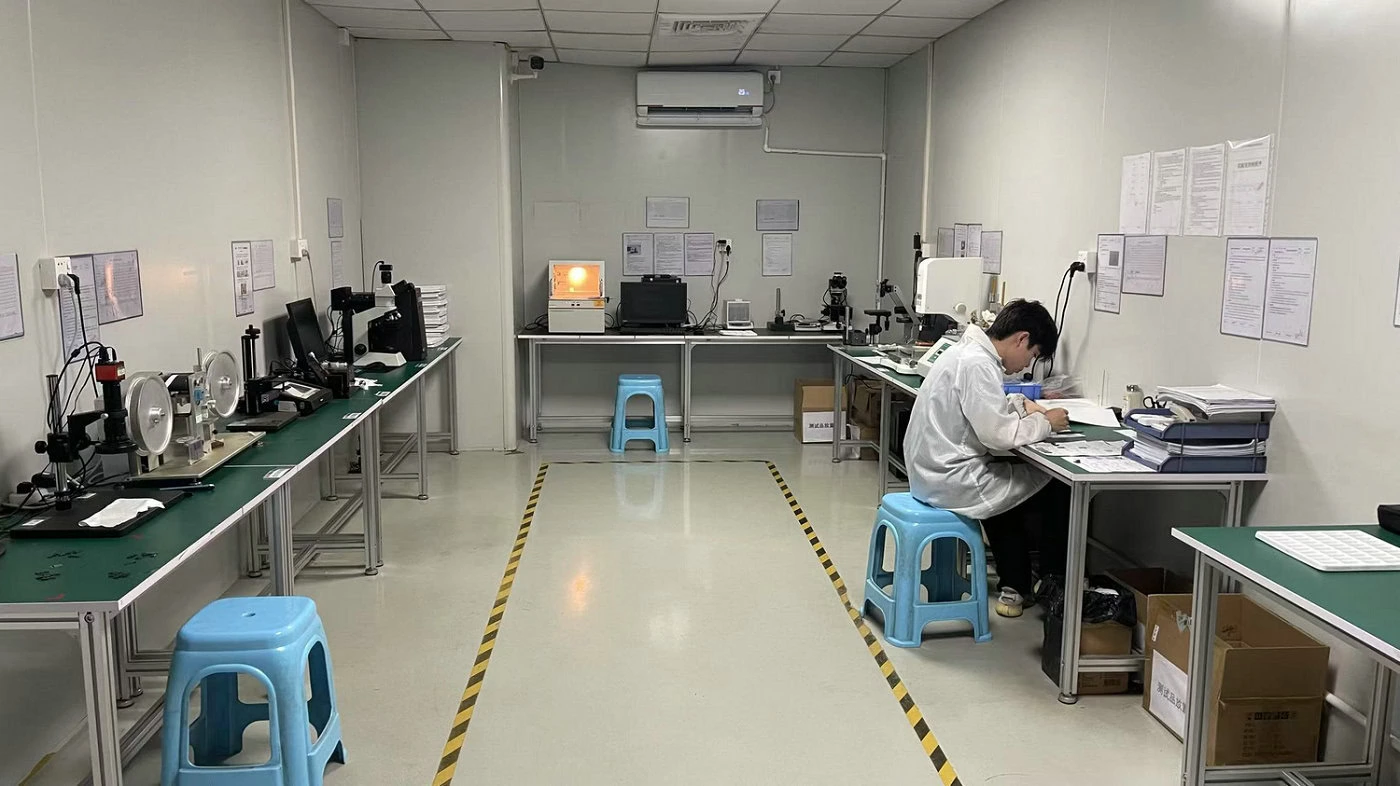
MIM dimensional control is influenced by molding, green-part handling, debinding, sintering shrinkage, support, secondary operations, and the measurement setup. The practical goal is to identify which dimensions and surfaces control function, then assign the right manufacturing and inspection strategy to them.
| Question | Why It Matters | Review Focus |
|---|---|---|
| Which dimensions are critical to function? | Not every dimension needs the same level of control. | Datums, assembly surfaces, functional interfaces, and tolerance priority. |
| Which features can remain as-sintered? | Near-net-shape production is where MIM creates much of its process value. | Molded feature capability, shrinkage behavior, and inspection method. |
| Which features need secondary machining? | Very tight tolerances or functional surfaces may require post-sintering control. | Machining allowance, datum transfer, and cost impact. |
| Is sizing or coining required? | Selected dimensions may need correction after sintering. | Geometry suitability, repeatability, and distortion risk. |
| How should surface condition be controlled? | Functional and cosmetic surfaces can require different finishing routes. | Polishing, passivation, PVD, tumbling, coating, and acceptance criteria. |
| What should be inspected first? | Inspection resources should follow product risk. | Critical dimensions, functional surfaces, material checks, and validation needs. |
Educational Scenario: Critical Dimension Control
- Scenario: A compact bracket contains several functional surfaces, but the drawing applies similar tolerance emphasis to both critical and non-critical dimensions.
- Why MIM may still fit: Much of the geometry may be produced near-net-shape while selected interfaces receive tighter secondary control.
- Main engineering risk: Without a clear datum and critical-to-function strategy, quotation, tooling compensation, machining, and inspection priorities become unclear.
- What to review: Functional datums, as-sintered dimensions, sizing or machining needs, measurement method, and acceptance criteria.
- Decision takeaway: A strong MIM drawing distinguishes the dimensions that drive function from dimensions that can use realistic process capability.
Related capability pages: quality control, inspection and testing, and secondary operations.
How XTMIM Reviews a Similar Part
If one of the scenarios resembles your project, the next step is to test the actual drawing against six decision areas.
1. Function
What must the part do under load, wear, corrosion, motion, sealing, magnetic, cosmetic, or assembly conditions?
2. Material
Which properties are required, and do the material, heat treatment, and finishing route support them?
3. Geometry
Which walls, holes, undercuts, flats, transitions, or mass imbalances create molding or sintering risk?
4. Tolerance
Which dimensions are critical to function, and which can follow realistic as-sintered capability?
5. Secondary Operations
Which features need sizing, machining, polishing, heat treatment, passivation, PVD, or another post-process?
6. Validation
How will critical dimensions, material properties, surfaces, and application-specific requirements be verified?
For more detail, see engineering review and MIM tooling.
What to Prepare for a MIM Engineering Review
A useful review needs more than a target unit price. The information below allows the supplier to evaluate manufacturability, tooling economics, critical features, secondary operations, and validation requirements.
| Information to Provide | Why It Matters |
|---|---|
| 2D drawing + 3D CAD | Defines geometry, dimensions, tolerances, datums, undercuts, wall thickness, and tooling features. |
| Material + heat-treatment requirement | Defines feedstock direction, sintering route, target properties, and post-treatment risk. |
| Critical dimensions + inspection requirement | Separates functional features from general dimensions and helps define secondary control and measurement. |
| Surface and finishing requirement | Clarifies polishing, passivation, PVD, coating, tumbling, cosmetic, or functional surface needs. |
| Estimated annual volume | Determines whether tooling investment and MIM production economics are reasonable. |
| Current manufacturing process | Shows where CNC, PM, stamping, casting, 3D printing, or assembly steps may be reduced or retained. |
| Application and operating conditions | Provides context for load, corrosion, wear, temperature, motion, sealing, magnetic, or assembly requirements. |
Use the MIM RFQ preparation guide to organize the project package, then submit drawings for review or request a quote.
Frequently Asked Questions About MIM Case Studies
Are these MIM case studies based on real customer projects?
Examples on this page are clearly labelled educational composite scenarios unless a case is explicitly identified as a published production reference. Confidential customer details are removed or generalized where necessary.
What does “educational composite scenario” mean?
It is a realistic engineering example built from recurring MIM review patterns and manufacturing issues. It explains the decision logic without claiming to describe a specific named customer project.
How should I choose which scenario to read first?
Start with your main engineering question. Use process conversion for CNC or alternative-process comparisons, geometry for thin walls or complex features, material performance for alloy selection, and tolerance and inspection for critical dimensions or functional surfaces.
Can these examples tell me whether my part is suitable for MIM?
They can support initial screening, but final suitability depends on the actual part size, geometry, material, tolerances, annual volume, secondary operations, and application conditions. A drawing-based review is still required.
What information should I send for a MIM review?
Provide the 2D drawing and 3D CAD file, material and heat-treatment requirements, critical dimensions, surface requirements, estimated annual volume, current manufacturing route, and application or inspection requirements.
Can XTMIM compare my part with one of these scenarios?
Yes. If your part has a similar manufacturing route, geometry, material, tolerance, or application challenge, XTMIM can review the drawing and identify the main DFM, tooling, secondary-operation, and inspection questions for your project.
Have a Similar MIM Part to Review?
Send the 2D drawing, 3D CAD file, material requirement, critical dimensions, surface or heat-treatment requirements, estimated annual volume, current manufacturing process, and application background. XTMIM can review MIM suitability, DFM risk, tooling and shrinkage, secondary operations, tolerance feasibility, and inspection needs before tooling or production planning.