
What Are Soft Magnetic MIM Materials?
Soft magnetic MIM materials are Fe-based metal injection molding alloys used for compact electromagnetic parts that must magnetize and demagnetize under an external field instead of acting as permanent magnets. Use this guide to compare Fe-3Si / Fe-3%Si, Fe-50Ni / Fe-50%Ni, and Fe-50Co / Fe-50%Co according to the required magnetic function, 3D geometry, sintered density, air gap control, heat treatment, residual stress, secondary operations, and finished-part validation before RFQ or tooling.
Compare Fe-3Si, Fe-50Ni, and Fe-50Co soft magnetic MIM material directions before choosing a specific alloy route.
Most suitable for compact solenoid, sensor, relay, yoke, pole piece, actuator, and flux guide components with 3D MIM geometry.
This is not a permanent magnet guide, motor lamination guide, transformer core guide, or general magnetic alloy reference page.
For the full material system, review the MIM materials overview. If the project has not yet defined a material direction, the MIM material selection guide can help frame the first review. Once the material direction is clearer, continue to the Fe-3%Si, Fe-50%Ni, or Fe-50%Co material page for alloy-specific chemistry, magnetic property direction, heat treatment considerations, and application-level validation.
Soft Magnetic MIM Materials Are Not Permanent Magnets
A common mistake is to group all “magnetic materials” together. Soft magnetic MIM materials are not selected to retain magnetism after the external field is removed. Their function is usually to respond to a magnetic field, guide flux, reduce magnetic reluctance, or support controlled actuation in an electromagnetic system.
This matters because the design question is different. For a permanent magnet, the user may care about retained magnetization and magnetic energy. For a soft magnetic MIM part, the real questions are permeability, coercivity, saturation behavior, magnetic response, losses, dimensional stability, stress condition, and how the part behaves after sintering and heat treatment.
Typical MIM soft magnetic applications include compact solenoid components, relay parts, magnetic sensor cores, pole pieces, yokes, flux guides, and small actuator components. If the design is mainly a large motor core, transformer core, or thin laminated magnetic stack, MIM is usually not the first process route to evaluate. For deeper part-type discussion, review soft magnetic MIM parts.
Main Soft Magnetic Material Families for MIM Projects
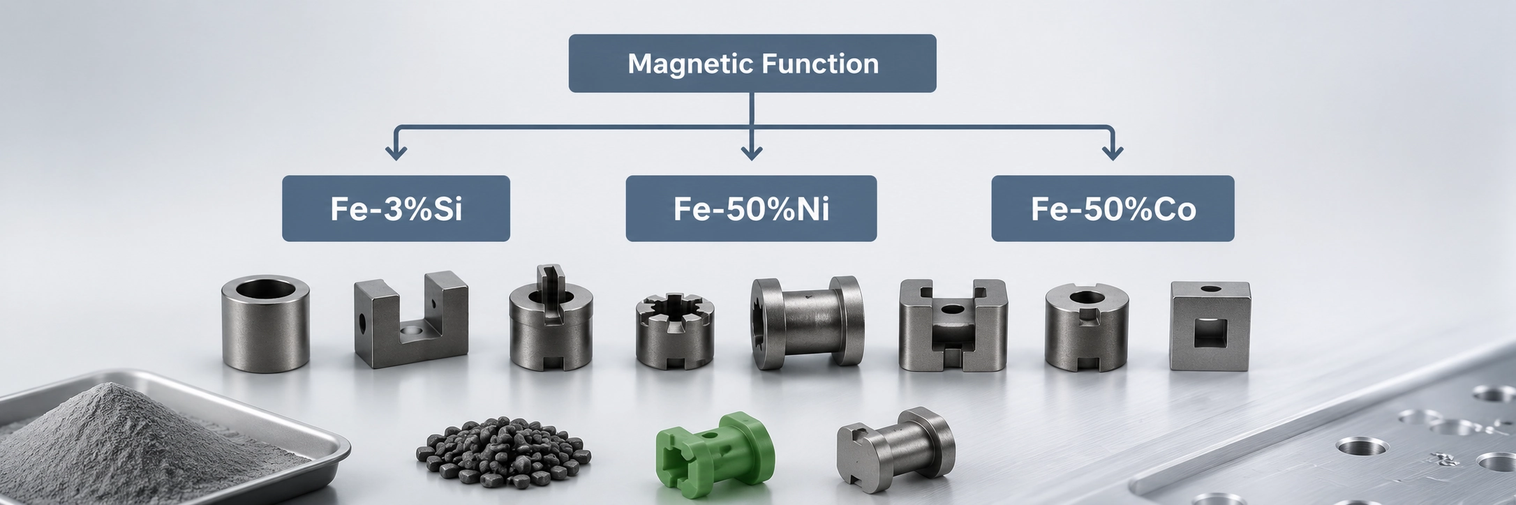
Soft magnetic MIM materials should be selected by application requirement, not by material name alone. Fe-3%Si, Fe-50%Ni, and Fe-50%Co represent different engineering directions: loss-related Fe-Si behavior, high-permeability Fe-Ni behavior, and high-saturation Fe-Co behavior. Their suitability still depends on part geometry, sintering result, heat treatment, final inspection method, and whether the finished part—not only a test coupon—can meet the application requirement.
Use the comparison below for the initial material-family decision, then continue to the dedicated Fe-3%Si, Fe-50%Ni, or Fe-50%Co page when alloy-specific chemistry, magnetic property direction, heat treatment assumptions, or application validation becomes the deciding factor.

| Material family | Main engineering reason to consider it | Typical project direction | Go deeper |
|---|---|---|---|
| Fe-3%Si | Often reviewed where electrical resistivity and loss-related behavior matter. | Solenoid cores, relay components, flux guides, compact electromagnetic parts. | Fe-3%Si material page |
| Fe-50%Ni | Often reviewed where high permeability and low coercivity direction matter. | Sensor cores, sensitive magnetic response parts, relay components. | Fe-50%Ni material page |
| Fe-50%Co | Often reviewed where high saturation magnetic performance is required. | Compact high-flux electromagnetic components, high-performance actuator parts. | Fe-50%Co material page |
The Metal Injection Molding Association materials range explains that MIM powders are available in different chemistries, particle sizes, and particle shapes. MPIF Standard 35-MIM covers common metal injection molding materials with explanatory notes and definitions. These references are useful for material specification discussions, but final approval still requires supplier-specific feedstock, sintering, heat treatment, and testing review.
Fe-3%Si for Resistivity and Loss-Related Review
Fe-3%Si is often considered when an engineer wants a soft magnetic MIM material direction associated with silicon steel behavior. In MIM projects, it may be reviewed for compact electromagnetic components where magnetic response and loss behavior matter, but the part geometry is too complex for a conventional flat laminated route.
The selection should not stop at “Fe-Si.” The review should include operating frequency, duty cycle, heat generation, geometry, critical air gaps, sintering condition, and whether the final magnetic test will be based on material coupons or finished parts.
Fe-50%Ni for Permeability and Low Coercivity Direction
Fe-50%Ni may be considered when the application needs a high permeability direction, low coercivity direction, or sensitive magnetic response. This can be relevant for compact sensor components, relay parts, and electromagnetic components where small changes in magnetic behavior affect function.
From a design review perspective, Fe-50%Ni should be evaluated together with air gap control, mating surface condition, residual stress, heat treatment, and the final magnetic measurement method. Aggressive post-machining or finishing may change local stress and surface condition.
Fe-50%Co for High Saturation Magnetic Performance
Fe-50%Co is typically considered when high magnetic saturation is a major requirement in a compact part. It may be relevant for high-flux electromagnetic components, small actuator systems, or applications where the part must carry stronger magnetic flux within limited space.
This material direction should be selected with care. The project must review cost sensitivity, geometry, sintering and heat treatment requirements, inspection method, and whether the application truly needs Fe-Co performance instead of a lower-cost soft magnetic route.
How to Choose a Soft Magnetic MIM Material
The best starting point is not “Which material is strongest?” but “What magnetic function must the part perform?” A soft magnetic MIM material should be selected according to the magnetic requirement, geometry, production route, and validation method. In practice, the same material family can behave differently if density, heat treatment, residual stress, or air gap control changes.
| Project requirement | Better material direction to review | Engineering note |
|---|---|---|
| Loss-related behavior is important | Fe-3%Si | Review operating frequency, duty cycle, heat treatment, geometry, and test method. |
| High permeability direction is important | Fe-50%Ni | Review air gap, geometry, surface condition, residual stress, and final magnetic response. |
| High saturation is important | Fe-50%Co | Review magnetic load, cost sensitivity, production feasibility, and validation needs. |
| Material target is not defined | Start with application review | Submit the drawing, working condition, magnetic function, and testing requirement. |
| Geometry is small and complex | MIM may be suitable | Review wall sections, green part handling, sintering distortion, gate location, and post-machining needs. |
| Part is simple and pressable | PM pressing may be better | Review cost, density, geometry, tooling, and production volume. |
| Part is a large laminated magnetic core | Stamping or laminations may be better | MIM is usually not the preferred route for large flat magnetic stacks. |
Material Decision Matrix Before RFQ
Before requesting tooling or a production quote, the material direction should be checked against both magnetic function and manufacturing feasibility. The table below is not a substitute for alloy-specific review; it helps identify which material direction deserves deeper validation before RFQ or tooling.
| Material direction | Best fit when | Use caution when | RFQ confirmation needed |
|---|---|---|---|
| Fe-3%Si | The part needs a soft magnetic direction associated with silicon steel behavior, electrical resistivity, or loss-related review. | The geometry, frequency, heat generation, or required test method has not been defined. | Operating frequency, duty cycle, heat treatment expectation, air gap, and finished-part magnetic test requirement. |
| Fe-50%Ni | The project needs a high permeability direction, low coercivity direction, or sensitive magnetic response. | The part has stress-sensitive machined surfaces, tight air gaps, or magnetic response that depends strongly on final assembly condition. | Critical mating surfaces, post-machining plan, magnetic annealing expectation, air gap tolerance, and functional response test. |
| Fe-50%Co | The application requires a high saturation magnetic performance direction in a compact component. | The project is cost-sensitive, the magnetic load is not confirmed, or a lower-cost material direction may satisfy the function. | Magnetic load, saturation requirement, production volume, cost sensitivity, heat treatment route, and finished-part validation method. |
| Not yet defined | The drawing exists, but the magnetic function or material direction is still open. | The RFQ only says “magnetic material” without target function, working condition, or inspection method. | 2D drawing, 3D CAD, current material if any, magnetic function, working environment, annual volume, and required test method. |
A practical review normally starts with four questions:
- What magnetic function does the part perform?
- What are the critical dimensions, air gaps, and mating surfaces?
- What final magnetic property or functional response must be tested?
- Can the required geometry be produced more efficiently by MIM than by PM pressing, CNC machining, stamping, or laminations?
Why MIM Processing Affects Magnetic Performance
Soft magnetic performance is not only a material chemistry issue. It is also affected by the full MIM route: fine metal powder and binder feedstock, injection molding, green part handling, debinding, sintering, heat treatment, secondary operations, and final inspection. This is why an RFQ that lists only the alloy name often leaves too much uncertainty for both the buyer and the manufacturer.
ASM International describes magnetically soft materials as being characterized by low coercivity and notes that magnetic behavior can be affected by impurities, alloying additions, heat treatment, residual stress, and grain size. In MIM, these become manufacturing review points because powder characteristics, debinding control, sintering atmosphere, residual porosity, carbon level, oxygen pickup, and post-processing can all influence the final part.
| Factor | Why it matters for soft magnetic MIM parts |
|---|---|
| Sintered density | Low density or residual porosity may reduce magnetic performance and mechanical reliability. |
| Carbon / oxygen / nitrogen control | Impurities can affect magnetic response, material condition, and batch consistency. |
| Sintering atmosphere | Atmosphere control can influence chemistry, density, oxide condition, and final material behavior. |
| Heat treatment or magnetic annealing | May be required to reduce stress or improve magnetic response, depending on alloy and application. |
| Secondary machining | Can introduce local stress or change critical mating surfaces and air gap behavior. |
| Surface finishing | May affect contact surfaces, corrosion behavior, coating thickness, or magnetic testing consistency. |
| Finished-part testing | The test method should match the actual function, not only a generic material value from a datasheet. |
For a broader process explanation, review the MIM process overview. For the stage most closely tied to density, shrinkage, and final material condition, see the MIM sintering process.
Typical Applications for Soft Magnetic MIM Materials
Soft magnetic MIM materials are most relevant when the part combines electromagnetic function with small size, complex geometry, repeatable production volume, and tight interface requirements. MIM is not selected simply because a material is magnetic. It is selected when the geometry and production requirements make metal injection molding a practical manufacturing route.
Common component directions
- Solenoid cores
- Armatures
- Relay components
- Magnetic sensor cores
- Pole pieces
Where MIM becomes relevant
- Yokes and flux guides
- Compact actuator components
- Small electromagnetic housings or inserts
- Complex magnetic path components with 3D features
For deeper part geometry, DFM risks, and component-specific application examples, continue to the dedicated soft magnetic MIM parts guide.
When MIM Is a Better Route for Soft Magnetic Components
MIM should be considered when the component is small, complex, three-dimensional, and difficult to make efficiently by pressing, machining, or stamping. It is not automatically better than every alternative. The right process depends on geometry, magnetic requirement, production volume, tooling budget, inspection method, and final assembly function.
| Process route | Better fit | Limitation for soft magnetic projects |
|---|---|---|
| MIM | Small, complex 3D components with repeated production demand. | Requires tooling, debinding and sintering control, shrinkage compensation, and validation before production. |
| PM pressing | Simple pressable shapes and cost-sensitive high-volume parts. | Limited 3D geometry, side-feature flexibility, and undercut capability. |
| CNC machining | Prototypes, low-volume runs, or simple magnetic parts. | Less efficient for complex repeated features, small internal shapes, and material utilization. |
| Stamping / laminations | Thin motor cores, transformer cores, and laminated magnetic stacks. | Not suitable for many compact 3D MIM geometries. |
| Casting | Larger or less precise shapes. | May not match small-feature precision or magnetic consistency needs. |
| Additive manufacturing | Early prototypes or complex low-volume structures. | Material properties, surface condition, and production economics require careful review. |
From a sourcing perspective, MIM becomes more attractive when the part has repeated production demand, multiple small features, difficult machining access, and enough annual volume to justify tooling. If the part is simple, flat, and easy to press or stamp, another route may be more practical.
Design and Quality Factors to Confirm Before Tooling
Soft magnetic MIM material selection should be reviewed together with design and inspection requirements. A material may appear suitable on paper but fail to meet functional needs if the air gap, mating surface, density, heat treatment, or post-machining plan is not controlled.
Design factors
- Magnetic path and functional air gap
- Critical dimensions related to magnetic response
- Mating surfaces and assembly interfaces
- Thin walls, slots, sharp corners, or fragile magnetic features
- Gate location and possible gate mark sensitivity
- Sintering distortion and support requirements
Quality and validation factors
- Need for secondary machining
- Surface finish or coating requirements
- Heat treatment or magnetic annealing requirement
- Dimensional inspection method
- Final magnetic testing method
- Application-level validation requirement
A common mistake is to specify only the alloy name and part tolerance without explaining how the part functions magnetically. For soft magnetic components, the same nominal material can behave differently if geometry, density, heat treatment, stress condition, and testing method are not aligned.
For detailed manufacturability review, see DFM for MIM. For critical dimensions, air gaps, and interface control, review MIM tolerances.
Representative Engineering Scenarios
These representative scenarios show how material and process decisions can go wrong when magnetic function, geometry, and validation are reviewed separately.
Material Chosen Before the Magnetic Test Method Was Defined
A compact electromagnetic component may reach the RFQ stage with only an alloy direction and dimensional tolerances on the drawing, while the required magnetic response and final test method remain undefined. In that situation, choosing a soft magnetic alloy family does not by itself define how the finished component must perform.
The underlying risk is that sintered density, heat treatment, residual stress, air gap condition, and inspection method may not be aligned before tooling. Two parts with the same nominal material direction can therefore produce different functional results if the production condition and validation method are not controlled together.
A better review sequence is to define the magnetic function, critical air gap, post-process condition, and agreed magnetic or functional test before production validation. The RFQ should include the drawing, application condition, material direction, heat treatment expectation, and final testing requirement where available.
Process Route Chosen Before the Geometry Was Reviewed
A small magnetic component with side features, thin sections, and a critical mating surface may initially be assigned to PM pressing simply because it is a magnetic part. That decision can become restrictive when the geometry includes three-dimensional features that are difficult to form by uniaxial compaction.
The more useful comparison is between the complete manufacturing routes. Geometry, tolerance, air gap, tooling path, production volume, and validation requirements should be reviewed alongside the magnetic material requirement rather than after a process has already been selected.
When the part needs greater 3D design freedom, MIM may become the better route to evaluate; when the geometry is simple and pressable, PM may still be more practical. The process decision should follow the combined review of material, geometry, volume, tooling, inspection, and validation.
What to Provide for a Soft Magnetic MIM Material Review
A useful RFQ should give the engineering team enough information to judge both material suitability and manufacturing risk. For soft magnetic MIM materials, the following information is more useful than a general request for a magnetic material quote.

| RFQ input | Why it matters |
|---|---|
| 2D drawing | Defines tolerances, datums, inspection requirements, and critical dimensions. |
| 3D CAD file | Helps evaluate moldability, undercuts, thin sections, parting line, gate location, and sintering risk. |
| Target material or current material | Provides the starting point for Fe-3%Si, Fe-50%Ni, Fe-50%Co, or another route. |
| Magnetic function | Shows whether the part is a core, yoke, pole piece, sensor part, actuator part, or flux guide. |
| Magnetic property target if available | Helps define permeability, coercivity, saturation, or application-level test needs. |
| Working temperature and environment | Affects material, heat treatment, coating, corrosion behavior, and long-term stability review. |
| Critical air gap or mating surface | Directly affects magnetic response and dimensional control. |
| Surface finish or coating requirement | May affect assembly, corrosion behavior, air gap, coating thickness, or test consistency. |
| Annual volume | Helps judge whether MIM tooling is commercially reasonable. |
| Current manufacturing process | Useful if replacing CNC, PM pressing, stamping, casting, or another route. |
Continue to Specific Soft Magnetic MIM Material Pages
Choose the next material review according to the magnetic requirement. The dedicated Fe-3%Si, Fe-50%Ni, and Fe-50%Co pages provide deeper guidance on alloy-specific chemistry, magnetic property direction, heat treatment considerations, process sensitivity, and application-level validation before RFQ or tooling evaluation.
Fe-3%Si Soft Magnetic MIM Material
Review Fe-3%Si when the project needs a soft magnetic material direction associated with electrical resistivity and loss-related considerations, especially for compact electromagnetic components where geometry is also important.
Fe-50%Ni Soft Magnetic MIM Material
Review Fe-50%Ni when high permeability direction, low coercivity direction, or sensitive magnetic response is important. This material direction is often more relevant when the part’s magnetic response must be carefully controlled.
Fe-50%Co Soft Magnetic MIM Material
Review Fe-50%Co when the project needs a high saturation magnetic performance direction in a compact component. This route should be evaluated carefully because performance requirements, cost, heat treatment, and validation needs are usually more demanding.
If the project requires a non-standard alloy direction, start with custom MIM materials and confirm feedstock feasibility, powder availability, sintering behavior, and testing requirements before tooling.
Request a Soft Magnetic MIM Material Review
For compact electromagnetic components, soft magnetic MIM material selection should be reviewed before tooling. Send your 2D drawing, 3D CAD file, target material, magnetic function, critical dimensions, air gap requirement, working environment, surface finish requirement, test method if available, and estimated annual volume. XTMIM’s engineering team can review whether Fe-3%Si, Fe-50%Ni, Fe-50%Co, or another material route is more suitable, and identify material, DFM, sintering, tolerance, and inspection risks before production planning.
FAQ About Soft Magnetic MIM Materials
Are soft magnetic MIM materials permanent magnets?
No. Soft magnetic MIM materials are not selected to retain permanent magnetism. They are used when a part must respond to an external magnetic field, guide flux, switch magnetic response, or support electromagnetic actuation. Typical examples include solenoid cores, armatures, pole pieces, yokes, and sensor cores. If the project requires permanent magnet behavior, the material selection route is different.
Which MIM material is better for solenoid cores?
There is no universal best material for all solenoid cores. Fe-3%Si may be reviewed where electrical resistivity or loss-related behavior matters. Fe-50%Ni may be reviewed where high permeability or low coercivity direction matters. Fe-50%Co may be reviewed where high saturation is required. The final choice depends on geometry, air gap, duty cycle, heat treatment, operating condition, and testing method.
When should Fe-50%Ni be considered instead of Fe-3%Si?
Fe-50%Ni may be considered when the project needs a high permeability direction, low coercivity direction, or sensitive magnetic response. Fe-3%Si may be more relevant where silicon steel behavior and loss-related considerations are important. The decision should be confirmed through application review, not only by comparing alloy names.
Why does heat treatment affect soft magnetic MIM performance?
Heat treatment can influence stress condition, microstructure, and magnetic response. In soft magnetic components, residual stress, impurities, density, and grain condition can affect magnetic behavior. Because MIM parts pass through debinding, sintering, and sometimes secondary operations, the final magnetic performance should be reviewed together with the complete process route.
Can MIM replace PM pressing for soft magnetic parts?
Sometimes. MIM is more suitable when the part is small, complex, three-dimensional, and difficult to press directly. PM pressing may be better for simpler shapes, cost-sensitive high-volume components, and parts with geometry suitable for compaction. The decision should compare material requirement, shape complexity, density needs, tooling cost, and production volume.
Can MIM replace stamped laminations?
Usually only for different part types. Stamped laminations are often better for thin motor cores, transformer cores, and laminated magnetic stacks. MIM is more relevant for compact three-dimensional components such as small cores, yokes, pole pieces, armatures, and complex magnetic path parts. The two routes should not be treated as direct replacements in every case.
Should soft magnetic properties be tested on material coupons or finished MIM parts?
Material coupons can help compare material direction, but they may not represent the final behavior of a finished MIM component. Finished-part performance can be affected by geometry, air gap, density, heat treatment, residual stress, machining, coating, and assembly condition. For critical electromagnetic parts, the acceptance method should be agreed before tooling and should include finished-part or application-level validation where the function depends on the final component geometry.
What information is needed for a soft magnetic MIM RFQ?
A useful RFQ should include 2D drawings, 3D CAD files, target material or current material, magnetic function, critical dimensions, air gap requirements, surface finish, heat treatment expectations, working environment, annual volume, and any required magnetic test method. This allows the supplier to review material suitability and manufacturing risk before tooling.
Standards & Technical References Note
Soft magnetic MIM material selection should be supported by material specifications, supplier-specific process review, and application-level validation. The MIMA Materials Range is relevant because it places magnetic alloys within the broader MIM material capability discussion. MPIF Standard 35-MIM is relevant for common MIM materials, explanatory notes, and specification communication. MIMA’s Standard 35-MIM information should be checked for the latest edition before formal specification work. ASM International information on magnetically soft materials supports the need to evaluate impurities, heat treatment, stress, and grain condition when reviewing magnetic behavior. Published values and standards are starting references; final acceptance should be based on agreed drawings, supplier process capability, heat treatment condition, inspection plan, and finished-part validation requirements.