Request a Metal Injection Molding Quote

Share your drawing, material requirements, annual volume, tolerance needs, or application details. Our engineering team will review your MIM project and respond with technical feedback or a quotation.

MIM Mold Design: Parting Lines, Slides & Ejection

MIM Design Guide · Tooling Review Before Mold Investment

MIM mold design decides whether a complex metal part can be molded, ejected as a green part, debound, sintered, inspected, and repeated in production without avoidable tooling risk. For a design engineer, the main question is not only whether the CAD geometry looks moldable. The more important question is whether parting lines, mold opening direction, slides, inserts, core pins, ejector locations, shut-off areas, and protected surfaces can support stable MIM production. A weak tooling decision at the green-part stage can create cracks, distortion, flash, surface marks, dimensional drift, or expensive T1 mold corrections. This page focuses on the mold-design decisions that should be reviewed before tooling release, especially for parts with side holes, undercuts, deep holes, thin slots, cosmetic surfaces, sealing areas, or tight functional dimensions.

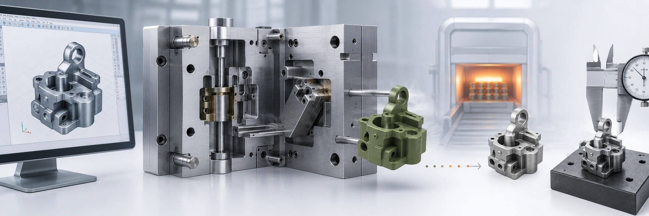
MIM mold design decision map showing CAD geometry, tooling layout, green part ejection, sintering shrinkage, and final inspection risk.
MIM mold design connects CAD geometry with tooling layout, green part handling, sintering shrinkage, and final inspection.
Core conclusion: Mold design decisions should be reviewed before tooling because they affect the full MIM production route, not only injection molding.
Best-fit parts Small, complex, high-volume precision metal parts where tooling can reduce machining, assembly, or part count.
High-risk features Side holes, undercuts, deep blind holes, thin slots, fragile ribs, and protected functional surfaces.
Key mold decisions Parting line, slides, inserts, core pins, ejection, shut-off, venting, and cavity layout.
Review before tooling Submit 2D drawings, 3D CAD, critical dimensions, protected surfaces, material, and volume.
Page scope: This page focuses on mold structure decisions such as parting line placement, mold opening direction, slides, inserts, core pins, ejector marks, protected surfaces, and tooling cost. Gate location, wall thickness, shrinkage compensation, and tolerances are connected topics, but they should be reviewed in their dedicated design pages.

What Should MIM Mold Design Solve Before Tooling?

MIM mold design should answer four practical questions before the customer invests in tooling: can the green part release from the mold without damage, can critical surfaces avoid unwanted marks, can side features be formed with acceptable tooling complexity, and can the mold layout support final dimensional control after debinding and sintering?

Metal injection molding starts with fine metal powder mixed with binder to form feedstock. After injection molding, the molded green component is removed before binder extraction and sintering. The MPIF overview of metal injection molding describes the route from green component removal through binder extraction and sintering, which is why mold release and green-part handling are not secondary details in MIM tooling.

From a design review perspective, MIM tooling should not be treated as a plastic injection mold copied into a metal part project. MIM may use injection molding principles, but the molded part must survive debinding, high sintering shrinkage, and final dimensional inspection after binder removal. Poor tooling decisions can remain visible or measurable in the final metal component.

Review Question Why It Matters What Should Be Checked Before Tooling
Can the part release from the mold? Mold release affects slides, parting line, draft, ejection, and green-part damage risk. Mold opening direction, undercuts, side features, ejector support
Are protected surfaces clearly marked? Gate marks, ejector marks, and parting lines may affect function or appearance. Sealing surfaces, sliding surfaces, cosmetic surfaces, datum surfaces
Are side holes or undercuts required? These may need slides, side cores, inserts, post-machining, or redesign. Feature direction, hole depth, tolerance, access for tooling
Are critical dimensions shrinkage-sensitive? Tooling layout and shrinkage compensation influence final dimensional control. Datum strategy, tolerance class, machining allowance, inspection method
Is tooling complexity justified by production volume? Slides and inserts can reduce secondary operations but may increase mold cost and maintenance. Annual volume, cost target, secondary machining alternatives

For the full drawing review workflow, see the DFM for MIM guide. This page focuses only on mold-design-related decisions before tooling.

Which Part Features Increase MIM Tooling Complexity?

Certain features are attractive because they reduce assembly, machining, or part count. In practice, the same features may increase tooling complexity if they require side action, long core pins, replaceable inserts, difficult shut-off areas, or protected surface planning.

The MIMA Design Center discussion of complex MIM designs explains that slides, cores, and other tooling elements can increase the complexity possible in MIM parts, but they usually add tooling and start-up engineering cost. Complexity is valuable when it replaces machining or assembly. It becomes a risk when the feature is not function-critical, creates avoidable flash, or makes the mold harder to maintain.

Simple MIM mold compared with slide, insert, and core pin tooling for side holes, undercuts, and complex molded metal features.
Side holes, undercuts, deep holes, and fragile slots may require slides, inserts, or core pins, increasing tooling cost and maintenance risk.
Core conclusion: MIM can form complex features, but tooling complexity must be justified by function, tolerance, and production volume.
Tooling Route or Feature Condition Typical Mold Impact Main Production Risk Better Design Review Action
Open-shut molded feature Can usually be formed in the main mold opening direction with lower tooling complexity. Lower mold mechanism risk, but parting line and ejector mark locations still need review. Keep non-critical features aligned with the main opening direction when function allows.
Side hole May require side core, slide, or post-sintering machining. Flash, tool wear, added mold cost, and longer tooling review. Review hole direction, tolerance, and whether the feature can be reoriented or machined after sintering.
Angled or cross hole May need more complex tool motion or a secondary operation. Higher mold complexity, alignment risk, and possible dimensional drift. Confirm whether the angled feature is function-critical before accepting complex tooling.
Internal undercut May require slide, collapsible action, insert strategy, or design simplification. Difficult release, higher tooling cost, and local flash risk. Evaluate redesign, split feature strategy, or secondary machining before tooling release.
Deep blind hole May require a long core pin with limited support. Core pin deflection, breakage, wear, and unstable hole geometry. Review depth-to-diameter ratio, hole tolerance, and whether a through hole or machining allowance is safer.
Thin slot May require fragile insert or tight shut-off surface. Insert wear, blocked slot, flash, and edge damage. Review minimum feature size, edge strength, and whether the slot should be molded or machined.
Protected cosmetic or functional surface Limits gate, ejector, parting line, and slide interface options. Visible marks, surface finishing conflict, or functional interference. Mark protected surfaces on the drawing before RFQ and define acceptable mark zones.
Tight datum near molded feature Increases mold layout, shrinkage control, and inspection demand. Dimensional variation after debinding and sintering. Review tolerance strategy, datum location, machining allowance, and inspection method together.

A common mistake is to ask the mold to create every feature in one operation without checking whether a simpler geometry, post-machined hole, or tolerance adjustment would reduce risk. A feature may be moldable, but not always economical or stable for mass production. For feature-specific guidance, review holes, slots, and undercuts in MIM design.

How Parting Line Placement Affects Function, Appearance, and Flash Risk

Parting line location should be decided with the part’s function in mind, not only with mold convenience in mind. A visible witness line may be acceptable on a non-functional surface, but it may be unacceptable on a sealing face, sliding face, cosmetic area, datum surface, or assembly interface.

MIM parting line and protected surface map showing gate mark, ejector marks, sealing surface, sliding surface, cosmetic surface, and datum area.
Protected surfaces should be identified before mold design so parting lines, gate marks, and ejector marks do not affect function or appearance.
Core conclusion: Parting line placement is a functional decision, not only a mold convenience decision.

In MIM, parting lines also matter because the molded green part still needs debinding and sintering. A parting line or shut-off mismatch that creates flash may require removal later, and that post-processing step can damage small features or change edge conditions. The issue is not only appearance. It can affect how the part assembles, seals, slides, or is inspected.

Surface Type Why It Should Be Protected Mold Design Concern
Sealing surface Flash or witness line may affect sealing performance. Avoid parting line, ejector marks, and gate vestige.
Sliding surface Raised marks may affect movement or wear. Control parting line and polishing requirements.
Mating surface Surface mismatch may affect assembly. Confirm flatness, mark location, and datum strategy.
Cosmetic surface Visible marks may be unacceptable. Plan gate, ejector, and parting line on less visible areas.
Inspection datum Mold marks may affect measurement repeatability. Keep datum surface stable and clearly specified.
Post-machined surface Molded condition may be less critical if machining is planned. Coordinate machining allowance and tooling layout.

If the drawing does not identify functional and cosmetic restrictions, the mold designer may place a gate, ejector pin, or parting line in a location that is technically moldable but unacceptable for final use. For deeper review of mark location and flow path, see MIM gate design and MIM tolerances.

When Are Slides, Inserts, and Core Pins Needed in MIM Tooling?

Slides, inserts, and core pins are used when a part has features that cannot be formed by a simple two-plate mold opening. They are common in MIM projects with side holes, cross holes, undercuts, internal pockets, small slots, bosses, and local details.

The better engineering question

The question is not only “Can MIM produce this feature?” A better question is: can this feature be molded repeatedly with acceptable tooling cost, maintenance risk, flash control, and dimensional stability?

Tooling Element Used For Main Risk What to Confirm Before Tooling
Core pin Holes, internal bosses, local cavities Pin deflection, wear, breakage, flash Hole depth, diameter, tolerance, feature direction
Slide / side action Side holes, undercuts, cross features Cost, maintenance, flash at slide interface Whether feature direction can be changed
Replaceable insert Local detail, wear area, fragile feature Insert fit, witness line, maintenance Whether insert replacement is expected
Shut-off surface Separating complex molded features Flash, mismatch, wear Shut-off angle, contact area, feature criticality
Post-machining alternative Holes or tight features not ideal for molding Extra operation cost Whether machining is lower risk than complex tooling

A side action may be justified when it eliminates multiple machined operations or allows several parts to be combined into one MIM component. It may not be justified if the feature is non-critical, avoidable, or easier to machine after sintering. For cost trade-offs, review MIM design for cost.

How Ejection Design Protects the MIM Green Part

Ejection design is especially important in MIM because the molded part is still a green part when it leaves the mold. It contains metal powder and binder, but it has not yet become the final dense metal component. The MIMA process overview explains the sequence from feedstock molding to binder removal and sintering, which is why green-part handling must be considered during tooling design.

MIM green part ejection risk diagram showing ejector pin placement, thin wall support, boss, rib, deformation risk, and protected surface zones.
Ejection design must protect the MIM green part before debinding and sintering because local stress can cause cracks, distortion, or visible marks.
Core conclusion: MIM ejector placement should be reviewed as a green-part protection issue, not only as a demolding function.

Poor ejection can create cracks, bending, local compression, deformation, or marks that remain visible after sintering. Thin walls, bosses, ribs, long flat sections, small projections, and asymmetric geometry all require careful ejection planning. In practice, ejector layout should be reviewed together with wall thickness, draft, protected surface notes, and sintering support orientation.

The proposed ejector layout and release direction should then be verified during the actual MIM injection molding process, where mold filling, cooling, mold opening, ejector movement, green-part release, and repeat-cycle stability can be observed together. A mold design should not be approved only because the part can be removed once; it should release consistently without cracking, distortion, sticking, or damage to protected surfaces.

Check Item Why It Matters Better Practice
Ejector mark location Marks may remain on the final part or affect assembly. Keep ejector marks away from sealing, sliding, cosmetic, and datum surfaces.
Thin wall support Thin sections may deform during ejection. Use wider support areas or modify local wall transitions.
Boss and rib layout Local thick/thin transitions can concentrate ejection stress. Review wall balance, radii, and ejector position together.
Flatness-sensitive surface Ejection force can introduce bending or distortion. Review ejector balance and sintering support together.
Fragile small features Pins, tabs, hooks, and small projections can break or distort. Add radius, adjust orientation, or review whether secondary operation is safer.

Composite Field Scenario for Engineering Training: Ejector Marks on a Functional Surface

What problem occurred A small MIM locking component had visible ejector marks on a surface used for sliding contact during assembly.
Why it happened The drawing did not identify the sliding surface as protected.
System cause The issue was a missing surface priority map during DFM review, not only ejector pin placement.
Correction The protected sliding surface was marked and ejector placement was moved to a less critical backside area.
Prevention Mark sealing, sliding, cosmetic, datum, and acceptable mark zones before RFQ.

How Shut-Off, Venting, and Flash Control Affect Molded MIM Quality

Flash control is a mold design issue, not only a trimming issue. In MIM, flash may occur around parting lines, side actions, core pins, small holes, slots, shut-off surfaces, or worn mold interfaces. Removing flash after molding or sintering may be possible, but it can increase cost, damage small features, or change edge conditions.

Shut-off surfaces define where mold steel contacts mold steel to block feedstock flow. If the shut-off area is too fragile, too sharp, poorly supported, or located around a critical feature, it may create repeatability problems. Venting also matters because trapped air can contribute to short shots, burn marks, or incomplete filling, but this topic should remain connected to mold design rather than become a full molding parameter discussion.

Risk Area Possible Cause Quality Impact Review Action
Parting line Poor alignment, wear, high local pressure Visible witness line, flash Review parting line location and shut-off fit.
Side action interface Slide mismatch or wear Flash around side hole or undercut Review slide direction, contact area, and maintenance risk.
Core pin area Small gap around pin Flash inside hole or local burr Review pin support and tolerance.
Thin slot Fragile insert or poor shut-off Blocked slot, flash, edge damage Review whether the feature should be molded or machined.
Vent area Over-venting or poor vent location Flash, surface defect Review vent size and placement through mold trial.

For molding-related quality causes beyond the tooling layout, see how injection molding affects MIM part quality and what affects part quality in MIM. For the specific quality-defect angle of tooling decisions, review mold-related quality risks in MIM parts.

MIM Mold Design Review Matrix Before RFQ

The most useful mold design review happens before RFQ or before tooling release. At this stage, design engineers and buyers should not only ask for a quote. They should provide enough information for the supplier to identify mold layout risk, surface restrictions, critical dimensions, and production assumptions.

MIM mold design review checklist showing 2D drawing, 3D CAD, protected surfaces, critical dimensions, material, volume, and tooling risk review before RFQ.
A useful MIM mold design review requires drawings, CAD files, protected surface notes, tolerance priorities, material requirements, and production volume.
Core conclusion: The better the RFQ input, the easier it is to identify tooling risks before mold investment.
Drawing Item Mold Design Risk What the Supplier Should Review Possible Action Before Tooling
Side hole Slide or side core may be required. Direction, access, tolerance, wall support Redesign hole direction, use slide, or machine after sintering
Internal undercut Complex tool motion may be required. Release direction, tooling feasibility, cost impact Simplify geometry or accept tooling complexity
Deep blind hole Long core pin may deflect or wear. Hole depth, diameter, tolerance, support Change to through hole, reduce depth, or post-machine
Protected cosmetic surface Gate, ejector, or parting mark may be unacceptable. Mark-free zones and acceptable mark zones Move marks to backside or non-functional area
Tight datum dimension Tooling and shrinkage may affect final dimension. Mold layout, shrinkage compensation, inspection datum Adjust tolerance, add machining allowance, or clarify datum
Thin wall near boss Ejection stress or filling imbalance may occur. Wall transition, ejector support, radii Add radius, adjust wall, or relocate ejector support
Flatness-sensitive area Ejection and sintering support may interact. Mold orientation, support surface, inspection method Review with sintering support strategy
High annual volume Multi-cavity tooling may be considered. Cavity balance, repeatability, maintenance Compare single-cavity, family mold, or multi-cavity strategy

For a practical pre-tooling review sequence, use the MIM DFM design checklist.

How Mold Complexity Affects Tooling Cost and Project Risk

Mold complexity affects cost because every additional slide, insert, side core, fragile shut-off, or precision feature adds design effort, manufacturing difficulty, trial risk, and maintenance demand. However, mold complexity is not automatically negative. It can be justified when it reduces CNC machining, eliminates assembly, improves repeatability, or supports high-volume production.

In practice, buyers should evaluate mold complexity together with expected annual volume, part function, tolerance needs, and the cost of alternative manufacturing routes. A simple mold with heavy secondary machining may not be cheaper overall, while an over-complex mold for a low-volume or non-critical feature may create unnecessary risk.

Cost Driver Why It Increases Risk or Cost When It May Be Justified
Slide or side action Adds moving mold mechanism and maintenance. When it eliminates expensive machining or assembly.
Replaceable insert Adds fitting and maintenance requirements. When local detail or wear area needs controlled replacement.
Long core pin May deflect, wear, or break. When the hole is functional and cannot be redesigned.
Multi-cavity tooling Requires cavity balance and higher upfront review. When annual volume supports tooling investment.
Tight shut-off feature Requires precise mold fit and maintenance. When the molded feature is essential to function.
Late T1 design change May require welding, re-cutting, or major tool modification. Should be reduced through early DFM review.

A practical purchasing question is not simply “Why is the mold expensive?” A better question is “Which geometry choices are creating tooling cost, and are those choices necessary for function?” For broader cost evaluation, review metal injection molding cost and MIM design for cost.

Common Mold Design Mistakes That Should Be Caught Before Tooling

Many mold-related problems are avoidable if the drawing is reviewed before tooling. The following mistakes are common because the part looks simple in CAD but behaves differently during mold release, green-part ejection, debinding, and sintering.

Common Mistake Production Risk Better Action
No protected surface notes on drawing Gate, ejector, or parting mark may affect function. Mark sealing, sliding, cosmetic, and datum surfaces.
Side holes placed without tooling review Slide or side core may increase cost and flash risk. Review whether direction, tolerance, or process can be changed.
Deep blind holes designed as molded features Core pin may deflect or break. Consider through hole, reduced depth, or secondary machining.
Tight tolerance applied to all dimensions Tooling and inspection cost may increase unnecessarily. Separate critical and non-critical dimensions.
Shrinkage treated as a simple scale factor Final dimensions may vary due to geometry and sintering behavior. Review shrinkage-sensitive features and inspection datum.
Ejector marks ignored until T1 Functional or cosmetic surfaces may be affected. Confirm acceptable mark zones before tooling.

Composite Field Scenario for Engineering Training: Avoidable Slide Increased Tooling Risk

What problem occurred A compact MIM bracket included a side hole that required a slide and created local flash risk.
Why it happened The CAD model came from a machined design where the side hole was easy to drill.
System cause The part was evaluated as geometry only, not as a tooling and production system.
Correction The side hole was moved to the main mold opening direction and tolerance was reviewed.
Prevention Each hole, slot, and undercut should be reviewed for function, direction, tolerance, and tooling risk.

For a broader mistake checklist, see common MIM design mistakes.

What Should You Send for a MIM Mold Design Review?

A useful MIM mold design review requires more than a part image or basic dimensions. The supplier should understand the part’s function, critical surfaces, tolerance priorities, material expectations, production volume, and whether the project is still flexible before tooling.

Information to Provide Why It Matters
2D drawing Shows tolerances, datums, surface notes, and inspection requirements.
3D CAD file Allows mold opening direction, undercuts, and tool motion to be reviewed.
Critical dimensions Helps identify shrinkage-sensitive and inspection-sensitive features.
Protected surfaces Prevents gate, ejector, and parting marks from being placed on functional areas.
Material requirement Affects feedstock choice, sintering behavior, properties, and application suitability.
Surface finishing requirement Affects allowed marks, polishing, machining, coating, or post-processing.
Estimated annual volume Helps determine whether tooling complexity and multi-cavity tooling are justified.
Application background Helps the engineering team understand load, wear, corrosion, assembly, or appearance needs.
Prototype or production stage Determines whether design changes are still practical before mold investment.

Before RFQ, mark these areas on the drawing

To make the mold design review more accurate, identify protected cosmetic surfaces, sealing surfaces, sliding surfaces, datum surfaces, critical dimensions, side holes, undercuts, thin slots, flatness-sensitive areas, and acceptable mark zones. This helps the engineering team review parting line, gate vestige, ejector marks, slide interfaces, shrinkage-sensitive dimensions, and secondary operation needs before mold investment.

The strongest review happens before tooling release. Once the mold is built, correcting parting line, gate, ejector, slide, or shrinkage-related problems can become slower and more expensive.

Submit Your Drawing for MIM Mold Design Review

If your part includes side holes, undercuts, deep holes, thin slots, protected cosmetic areas, sealing surfaces, tight datum dimensions, or high-volume production requirements, send your project information for a mold design and DFM review before tooling release.

2D drawing and 3D CAD file Critical dimensions and tolerance priorities Material and surface finishing requirements Protected functional or cosmetic surfaces Estimated annual volume and project stage Application background and assembly requirements

XTMIM can review mold opening direction, parting line placement, gate and ejector mark restrictions, slides, inserts, core pins, shut-off risk, shrinkage-sensitive dimensions, and whether any geometry should be simplified before mold investment, trial production, or repeat production.

Upload Your Drawing / Contact Engineering Team

FAQs About MIM Mold Design

What is MIM mold design?

MIM mold design is the tooling planning process that turns a part drawing into a moldable green component. It includes cavity layout, parting line placement, mold opening direction, slides, inserts, core pins, ejection, shut-off surfaces, venting, and mark location. In MIM, the mold design must also consider debinding, sintering shrinkage, final dimensions, and inspection requirements.

How is MIM mold design different from plastic injection mold design?

MIM uses injection molding principles, but the molded part is not the final product. It is a green part made from metal powder and binder. After molding, the binder must be removed and the part must be sintered into a dense metal component. This means mold design must consider green-part strength, ejection damage, shrinkage, sintering behavior, and final dimensional control.

Why does parting line placement matter in MIM?

Parting line placement matters because it can affect appearance, flash risk, assembly, sealing, sliding function, and inspection. A visible parting line may be acceptable on a non-critical surface, but it should usually be avoided on sealing surfaces, sliding surfaces, cosmetic areas, datum surfaces, and close-fit assembly areas.

When does a MIM part need slides or side actions?

A MIM part may need slides or side actions when it includes side holes, undercuts, cross holes, or features that cannot release in the main mold opening direction. However, slides increase tooling cost, maintenance demand, and flash risk. The supplier should review whether the feature is function-critical or whether redesign or secondary machining is more practical.

Do side holes or undercuts always require slides in MIM tooling?

Not always. Some side holes or undercuts can be redesigned, reoriented, simplified, or machined after sintering. Slides or side cores are usually considered when the feature is function-critical and when the expected production volume justifies added tooling cost, maintenance, and flash-control risk.

Can MIM produce undercuts and side holes?

Yes, MIM can produce certain undercuts and side holes, especially when the production volume and part function justify the tooling complexity. However, not every undercut should be molded. Some features are better redesigned, simplified, or machined after sintering if tooling risk is too high.

Do ejector pin marks remain on final MIM parts?

They can. Ejector marks created during green-part removal may remain visible or affect functional surfaces after debinding and sintering. If a surface is cosmetic, sealing, sliding, or used as an inspection datum, it should be marked as protected before mold design.

What files are needed for a MIM mold design review?

A useful review usually requires a 2D drawing, 3D CAD file, material requirement, critical dimensions, tolerance priorities, protected surface notes, surface finishing requirements, estimated annual volume, and application background. These inputs help the supplier review mold release, tooling complexity, ejection, shrinkage-sensitive dimensions, and production feasibility.

Reviewed by XTMIM Engineering Team

This article is reviewed from a MIM manufacturing and DFM perspective, with attention to process suitability, material selection, tooling risk, green-part handling, debinding and sintering influence, tolerance requirements, inspection planning, and production feasibility. The guidance is intended for early design review and RFQ preparation. Final decisions should be confirmed through project-specific drawing review, material selection, tooling design, and supplier process validation.

Standards and Technical References Note

This page references MIMA and MPIF materials only where they support MIM process understanding, tooling complexity, green-part handling, or material specification. The MIMA Design Center is relevant for complex MIM design and tooling considerations. The MPIF MIM process overview is relevant for understanding green component removal, binder extraction, and sintering. MPIF Standard 35-MIM is relevant for material specification, but it should not be treated as a mold design standard. Mold layout, tolerance capability, and production feasibility still require project-specific DFM review.