MIM Process Quality Guide In metal injection molding, many defects that buyers notice at final inspection do not truly start at final inspection. They often begin during molding, when powder-binder feedstock is injected through the tool, packed into the cavity, cooled, ejected, and transferred as a fragile green part. Quick Answer Injection molding affects MIM …
MIM Process Quality Guide
In metal injection molding, many defects that buyers notice at final inspection do not truly start at final inspection. They often begin during molding, when powder-binder feedstock is injected through the tool, packed into the cavity, cooled, ejected, and transferred as a fragile green part.
Quick Answer
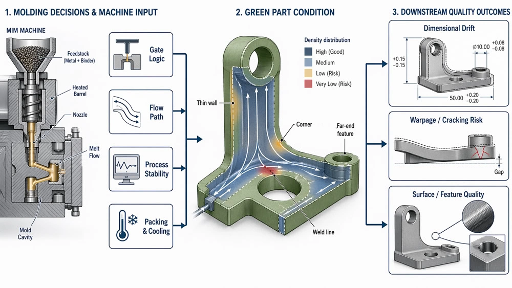
Injection molding affects MIM part quality by controlling how feedstock fills the cavity, how pressure is transferred during packing, how air escapes through the mold, and how safely the fragile green part is ejected and handled. Even when a molded green part looks complete, poor flow balance, unstable packing, excessive shear, weak venting, or ejection damage can later appear as distortion, cracking, density variation, surface inconsistency, or dimensional drift after debinding and sintering.
This article focuses on molding-stage quality risk. Material behavior, mold design, part geometry, debinding, sintering, and final dimensional control are covered in separate articles within the MIM part quality series.
Green density foundation: molding must create a uniform and stable green part before thermal processing can work predictably.
Key molding risks: fill imbalance, gate sensitivity, air traps, unstable packing, excessive shear, and ejection damage.
Buyer value: the page helps OEM engineers connect molding conditions with later distortion, cracks, density variation, and repeatability problems.
Why the Molding Stage Matters More Than Many Buyers Expect
According to the Metal Injection Molding Association process overview, MIM is valued for complex-shape production with good dimensional tolerance control and high-rate multi-cavity tooling. The European Powder Metallurgy Association also describes MIM as a process for complex parts in high quantities, with sintered densities commonly above 95%. Those advantages are real, but they only hold when the green part leaving the molding press is consistent enough for the rest of the process to work predictably.
In practical terms, the molding stage has one main quality job: create a green part with uniform fill, controlled binder-powder distribution, low internal stress, and enough integrity to survive transfer, debinding, and sintering. When that does not happen, later process steps are forced to carry a problem they did not create.
Engineering note: a part can look acceptable right after molding and still be at risk. Visual appearance alone is not proof of good molding quality in MIM.
Molding should also be reviewed together with the surrounding engineering decisions. Part geometry affects flow length, section balance, ejection risk, and green-part handling. Mold design determines gate position, venting, cooling, runner logic, and support during release. Material selection and feedstock behavior influence viscosity, shear response, green strength, and shrinkage stability. The molding stage is therefore a process-control point, but it cannot be separated from part design, tooling, materials, and downstream thermal behavior.
The Molding Decisions That Most Strongly Affect MIM Part Quality
Not every molding variable has the same impact. In real projects, the biggest quality effects usually come from fill balance, gate position, venting, packing stability, shear control, temperature control, and green-part release. These decisions determine whether the molded part has a stable density distribution or whether later processing must deal with hidden variation.
1) Fill balance and flow path control
If the cavity does not fill uniformly, the part can develop local density variation, weld-line weakness, air entrapment, or uneven shrinkage later. This is especially important in thin sections, long flow paths, multi-gate parts, and geometries with abrupt thickness transitions.
2) Gate position and gate strategy
Gate location affects how the feedstock enters the cavity, where flow fronts meet, how pressure is transferred, and which areas are more likely to see hesitation, jetting, weld-line sensitivity, or binder-rich flow behavior. A poor gate decision can create problems that no later setting change fully removes.
3) Venting quality
Poor venting makes air harder to evacuate and increases the risk of short shots, burn-like marks, trapped-gas defects, and unstable fill. In MIM, weak venting can also amplify local nonuniformity that later becomes visible after debinding or sintering.
4) Shear, temperature, and pressure stability
MIM feedstock is not ordinary plastic. When shear and temperature move outside a controlled range, powder-binder behavior becomes less stable. That can hurt moldability, green strength, surface finish, and dimensional repeatability.
5) Packing and green density consistency
A part that is under-packed or unevenly packed may leave the tool looking complete but still carry internal density differences. Those differences often become distortion, shrinkage inconsistency, or cavity-to-cavity variation later.
6) Ejection and green-part handling
Even a well-filled part can lose quality during ejection if the green part is stressed, dragged, bent, or impacted. Marks, hidden cracks, edge damage, and geometry shift often start here, not in sintering.
Several academic and engineering references on powder injection molding emphasize the same basic point: molding quality is tied to rheology, cavity filling behavior, air evacuation, and the way density uniformity is established before thermal processing. A useful technical example comes from the Center for Advanced Vehicular Systems (Mississippi State University) PIM simulation paper, which highlights simulation of filling time, gate position, weld lines, and air traps as practical tools for controlling molding-related risk.
For projects where wall thickness, holes, slender features, or abrupt section changes are part of the quality concern, it is also useful to review how part dimensions affect final MIM part quality. Dimensional risk and molding risk are separate topics, but they often interact in the same part.
How Gate Logic Changes Fill Balance and Visible Quality
Gate logic is often underestimated because buyers tend to focus on the finished part shape, not on how the cavity is actually filled. In MIM, gate logic directly influences the flow path, the meeting points of flow fronts, the pressure history of different regions, and the final uniformity of the green part. A gate that looks convenient for tooling may still create quality risk if it drives unstable filling or traps air in critical features.
A good gate strategy normally does four things well: it fills the cavity with balanced flow, reduces hesitation zones, places weld lines in lower-risk areas, and supports more even packing. A poor gate strategy tends to do the opposite: it creates longer weak flow paths, unstable front meeting, trapped air, local overpacking, or local underpacking. This is why gate review should connect molding trials with mold design review, not remain a press-setting discussion only.

What a good gate decision usually looks like
- The flow front reaches critical areas in a controlled and predictable sequence.
- Thin sections are not starved by thicker upstream zones.
- Air has a realistic path out of the cavity.
- Weld lines are moved away from cosmetic or structural high-risk zones where possible.
- Ejection, trimming, and downstream handling remain practical after molding.
What a poor gate decision usually causes
- Visible or hidden weld-line weakness.
- Short-shot sensitivity in thin or distant features.
- Jetting or unstable surface texture near the entrance region.
- Local overpacking or underpacking.
- Density variation that only becomes obvious after sintering.
This is one reason good MIM suppliers do not separate molding settings from tool design review. Gate quality belongs to both molding and tooling. For a tooling-focused view of gate position, venting, ejection support, and cavity balance, see How Mold Design Affects Part Quality in MIM.
Why a Stable Process Window Matters More Than One Good Sample Run
A common buyer mistake is judging molding quality from one acceptable sample batch. In real MIM production, that is not enough. The real test is whether the process can stay stable across cavity-to-cavity variation, machine-to-machine variation, material-lot changes, start-up conditions, and routine production shifts.
That is why a stable process window matters more than a one-time good result. A process that only works at a very narrow setting point is usually more fragile in mass production. In contrast, a robust process window gives the factory more room to control repeatability without constant firefighting.

What usually defines a stable molding window in MIM
- Fill is complete without relying on aggressive emergency settings.
- Pressure transfer is consistent from shot to shot.
- Part weight and critical dimensions stay within a predictable range.
- Green parts can be handled without frequent cracking or edge damage.
- Downstream distortion and scrap do not spike when production pace changes.
Process stability also supports better quality investigation. If the window is stable, later defects are easier to trace. If the window is unstable, root-cause analysis becomes much harder because too many variables move at the same time.
For broader materials data and benchmark values, readers can also refer to the Global PM Property Database, a joint resource developed by MPIF, EPMA, and JMPA to support realistic PM and MIM material comparisons.
Practical Signs That Molding Quality Needs Engineering Review
Some molding issues are easy to miss because the green part may still look complete. A molding-stage review is especially useful when one or more of the following signs appear during trial, pilot production, or repeat lots.
- Delayed distortion: parts look acceptable after molding but bend, twist, or shrink unevenly after sintering.
- Unstable thin features: thin sections, long flow paths, or sharp transitions show inconsistent fill or short-shot sensitivity.
- Gate-area surface marks: visible marks appear near gates, weld-line regions, or air-trap zones.
- Green-part damage: parts crack, bend, chip, or deform during ejection, collection, loading, or transfer.
- Repeat-lot drift: one sample batch passes, but later lots show dimensional drift, surface inconsistency, or cavity-to-cavity variation.
These signs do not automatically prove that molding is the only root cause. They indicate that molding history, green-part condition, tool design, and downstream debinding and sintering response should be reviewed together before changing one process parameter at random.
Why Molding-Origin Defects Often Appear Later in Debinding or Sintering
One of the most confusing things in MIM quality control is timing. The defect that becomes visible during debinding or sintering is not always caused during debinding or sintering. In many cases, the thermal stage is only where the earlier weakness finally becomes visible.
Examples are common. A hidden density difference created during molding can become differential shrinkage during sintering. A local crack initiated during ejection can open further during debinding. Flow imbalance can turn into distortion because different regions do not densify at the same rate. Surface inconsistency can become more obvious after binder removal and final shrinkage.

This is exactly why process-stage blame can become misleading. When a sintered part warps, the team should not automatically assume the furnace is the only issue. The correct question is whether the green part entered debinding in a truly uniform and stable condition.
That cross-stage logic is covered in more detail in How Debinding and Sintering Affect Part Quality in MIM. The thermal-stage article explains how binder removal, shrinkage behavior, support conditions, and sintering stability can expose weaknesses that were already built into the green part.
A Practical Engineering Checklist for Evaluating Molding Quality Risk
When you evaluate a new MIM supplier or review a troublesome part, these are the most useful molding-stage questions to ask.
- Gate review: Was gate position chosen based on actual fill behavior and not only tooling convenience?
- Flow balance: Are long-flow, thin-wall, or sharp-transition areas known and validated?
- Venting: Is air evacuation treated as a real design topic, not an afterthought?
- Robust process window: Can the supplier explain the acceptable range, not only one nominal setting?
- Green-part handling: Is there a clear method to protect fragile parts during ejection, collection, loading, and transfer?
- Cross-stage traceability: When defects appear after sintering, does the team trace them back to molding history and green-part condition?
- Verification method: Are downstream property and density checks tied to recognized standards when required by the project?
For projects requiring formal property verification, it is useful to align discussions with recognized references such as MPIF Standard 35-MIM for MIM material property data, ASTM B962 for density testing of PM products using Archimedes’ principle, and ISO 2740:2023 for tensile test pieces used for sintered metals, including MIM and sintering. These standards do not solve molding problems by themselves, but they help quality discussions stay objective.
Continue the MIM Part Quality Series
Injection molding is one part of the full MIM quality chain. Use the related articles below to separate molding-origin risks from design, feedstock, tooling, thermal processing, and dimensional-control issues.
- What Affects Part Quality in MIM? — overview of the complete process and design quality chain.
- How Feedstock Affects Part Quality in MIM — feedstock behavior, mold filling, green strength, and shrinkage consistency.
- How Part Design Affects Part Quality in MIM — geometry, wall thickness, transitions, and handling risks.
- How Material Selection Affects MIM Part Quality — material choice, sintering response, and property expectations.
- How Mold Design Affects Part Quality in MIM — gate, venting, ejection, and tooling stability.
- How Debinding and Sintering Affect Part Quality in MIM — thermal-stage causes and delayed defect visibility.
- How Part Dimensions Affect Final MIM Part Quality — dimensional risk, section balance, and final inspection concerns.
Need to Review a MIM Part for Molding-Stage Quality Risk?
If your part has thin sections, long flow paths, visible gate-area marks, repeat-lot drift, or distortion after sintering, the drawing should be reviewed together with molding, tooling, material, debinding, sintering, and inspection requirements.
Final Takeaway
Injection molding quality in MIM is not just about whether the cavity fills. It is about whether the molding stage creates a green part that is uniform enough, strong enough, and stable enough for everything that follows. When molding is well controlled, later stages become easier to stabilize. When molding is weak, the rest of the process spends time exposing problems that were already built in.
So if your goal is better MIM part quality, do not only ask whether the finished part passed. Ask whether the molding stage built the right foundation for the finished part to exist at all.
FAQ
No. In MIM, a green part can look acceptable and still contain flow imbalance, density variation, hidden stress, or small damage from ejection and handling. Those issues often become obvious only during debinding or sintering.
Gate location changes how the cavity fills, where flow fronts meet, how pressure is distributed, and where weld lines or hesitation zones form. That directly affects green density uniformity and later dimensional stability.
Yes. This is common in MIM. The root cause may start during molding, while the visible symptom only appears later when the part goes through debinding, sintering, sizing, or final inspection.
No. The real test is whether the process is stable across normal production variation. A supplier should be able to explain a robust process window, not just show a single successful trial.
They should be reviewed separately for clarity, but not treated as unrelated. Molding quality depends on part design, feedstock behavior, tool design, debinding, and sintering, so root-cause review should connect these stages.