
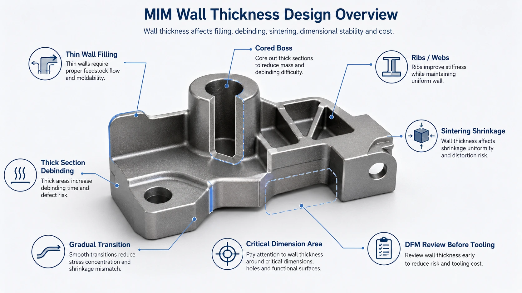
Quick Answer: Recommended MIM Wall Thickness Range
For early MIM design screening, a wall-thickness range of about 1.0–4.0 mm is a practical starting zone for many conventional parts. Sections around 0.4–1.0 mm should be treated as thin-wall features and reviewed for flow length, gate location, green-part strength, and sintering support. Sections around 4.0–6.0 mm require closer review of local mass, binder-removal distance, shrinkage balance, and distortion risk. Above 6.0 mm, coring, hollowing, ribs, or another process route should normally be evaluated before tooling.
Wall Thickness Screening Table
| Nominal Wall Thickness | Early Screening Classification | Main Engineering Risk | Recommended Review Action |
|---|---|---|---|
| Below 0.4 mm | Special thin-wall or micro-feature review | Incomplete filling, weak green-part handling, local distortion, and supplier-specific process limits | Do not treat as a standard capability. Confirm material, localized feature length, gate distance, mold venting, handling method, and validation plan with the MIM supplier. |
| 0.4–1.0 mm | Thin-wall design zone | Flow resistance, short shot, fragile green sections, and warpage when the feature is long or unsupported | Keep the thin section short and supported where possible. Review gate direction, flow length, radii, nearby holes or slots, ejection, and sintering support. |
| 1.0–4.0 mm | Preferred early-screening zone for many conventional MIM parts | Risk is usually driven more by abrupt transitions, local mass buildup, and tolerance location than by the nominal number alone | Use this as a starting range, then verify wall balance, feature length, material, critical dimensions, and support conditions before tooling. |
| 4.0–6.0 mm | Thick-section review zone | Longer debinding path, local shrinkage mismatch, sink or internal defect risk, distortion, and higher material cost | Review whether the area can be cored, hollowed, ribbed, tapered, or moved away from critical dimensions. |
| Above 6.0 mm | High-mass redesign or supplier-validation zone | Debinding and sintering become less forgiving, while cycle time, material consumption, distortion risk, and cost increase | Do not assume the section is impossible, but require project-specific validation. Prioritize coring or another geometry strategy; compare another manufacturing process when the mass is functionally unavoidable. |
How to use these numbers: They are screening references, not guaranteed production limits. Published MIM design envelopes differ because feasibility changes with material, overall part size, localized feature length, feedstock behavior, mold design, debinding route, sintering support, tolerance, and inspection requirements.
After the numerical screen, review the wall-thickness map as one manufacturing system:
- Thin regions: Can feedstock reach and fill the feature without creating a fragile green part?
- Thick regions: Can local mass be reduced without weakening the load path or assembly function?
- Transitions: Are thick-to-thin changes gradual, radiused, and separated from critical datums?
- Support-sensitive geometry: Can flat, thin, or cantilevered areas be controlled with suitable sintering support?
What Is a Good Wall Thickness for MIM Parts?
A good MIM wall thickness is not simply the smallest dimension a supplier can mold. It is a thickness that can be filled, handled as a green part, debound, supported during sintering, and inspected consistently at production volume. For early screening, start with the 1.0–4.0 mm range where the function allows, then identify every local region that falls below or above it.
Walls in the 0.4–1.0 mm range may be feasible when they are short, close to a suitable gate, supported by surrounding geometry, and not burdened by aggressive flatness or cosmetic requirements. Sections in the 4.0–6.0 mm range deserve a separate mass-distribution review because a part can mold successfully and still develop debinding, shrinkage, distortion, or cost problems later in the process.
Judge the Wall as a Geometry System, Not an Isolated Number
The most important question is how each wall interacts with feature length, nearby bosses and ribs, holes or slots, gate direction, critical dimensions, and sintering support. A short supported thin wall may be lower risk than a solid boss beside a tight-tolerance hole. Likewise, a nominally acceptable wall can become unstable when it connects abruptly to a heavy local mass.
Engineering decision rule: First screen the nominal thickness, then review wall uniformity, transition geometry, local mass, flow length, support conditions, and tolerance location. Final approval should come from the drawing and 3D model—not from one published minimum or maximum value.
Before tooling, mark thin walls, thick bosses, ribs, unsupported surfaces, abrupt transitions, and critical datums on the drawing. Review them together with the main MIM design guide, MIM gate design, shrinkage compensation, and MIM tolerances. For a broader quality perspective, see how part design affects MIM part quality.
Why the Same Wall Thickness Behaves Differently Across the MIM Process
A wall thickness that looks acceptable in CAD can behave differently during injection, green-part handling, debinding, and sintering. MIM feedstock must first fill the mold, but the molded part must also survive handling, release binder without internal damage, shrink predictably, and meet the final tolerance. This is why the numerical screening range is only the first decision.
The risk also changes with feature length and location. A localized 0.5 mm wall near the gate is not equivalent to a long 0.5 mm wall at the end of the flow path. A 5 mm mounting feature that is cored and gradually connected is not equivalent to a solid 5 mm block beside a critical bore.
Process-Stage Wall Thickness Check
| Process Stage | What Wall Thickness Changes | Typical Failure Signal | Drawing / DFM Question |
|---|---|---|---|
| Injection molding | Flow resistance, pressure balance, packing, weld-line location, and air escape | Short shot, incomplete rib, weld line, trapped gas, or local underfill | Is the thin region too long, too far from the gate, or interrupted by holes, slots, or sharp transitions? |
| Green-part handling | Local strength during ejection, degating, inspection, and tray loading | Cracked arm, damaged edge, bent rib, or broken thin feature | Can the feature be ejected and handled without relying on final-metal strength? |
| Debinding | Binder-removal distance and sensitivity of heavy local mass | Internal defect, cracking, blistering, or an unnecessarily narrow process window | Can thick areas be cored or connected with a more gradual mass transition? |
| Sintering | Shrinkage balance, gravity response, support contact, and local distortion | Warpage, flatness loss, hole shift, bore distortion, or dimensional drift | Is a critical feature located near a thick-to-thin transition or unsupported surface? |
| Final inspection | Stability of datums and critical dimensions after shrinkage | Unstable Cpk, high rejection risk, or unexpected need for secondary machining | Should the dimension remain as-sintered, receive machining allowance, or use another datum strategy? |
For more detail on the first and later process stages, see how feedstock affects MIM part quality and how debinding and sintering affect part quality in MIM.
Why Wall-Thickness Balance Matters More Than One Number
Uniform wall thickness does not mean that every feature must have exactly the same dimension. It means avoiding unnecessary local mass, abrupt section changes, and unsupported thin regions so that feedstock flow, binder removal, shrinkage, and measurement remain predictable. MIMA and EPMA design guidance both emphasize uniformity, coring, ribs or webs, and gradual transitions as practical ways to control these risks.
Balance Flow Length with Thin-Wall Geometry
Thin-wall feasibility depends on more than the minimum number in the drawing. Feature length, distance from the gate, nearby holes or slots, flow direction, venting, and green-part support determine whether the section can be filled and handled reliably. When a thin functional arm must remain, reduce abrupt restrictions and give the flow path and transition geometry enough support.
Reduce Local Mass Before Tightening Process Controls
A thick boss or solid block may create a longer binder-removal path and a different shrinkage response from the surrounding wall. Before relying on a narrower process window, review whether the mass can be cored, hollowed, replaced with ribs or webs, or connected through a taper or radius. The redesign should preserve the load path and assembly function while removing material that adds process risk but little functional value.
Keep Critical Dimensions Away from Unstable Transitions
Hole position, bore roundness, flatness, parallelism, concentricity, and mating-surface location are harder to stabilize when their datums cross an abrupt thickness change. The tolerance may be reasonable in isolation but difficult in that geometry. Place critical dimensions in stable sections where possible, and review shrinkage compensation, sintering support, datum selection, and machining allowance together.
Practical takeaway: Use the numerical screening table to identify risk zones, but use the wall-thickness map to make the final decision. The relationship between adjacent sections usually matters more than whether one isolated dimension is inside a published range.
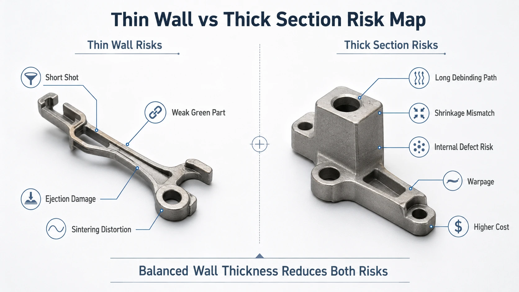
Thin Wall Risks in MIM Part Design
Thin-wall MIM parts can be feasible, especially when the part is small, the flow length is short, the geometry is well supported, and the tolerance requirement is realistic. However, thin walls should not be treated as a simple “minimum thickness” question. The same wall thickness may behave differently depending on flow length, gate position, material, part size, feature density, and nearby transitions.
Incomplete Filling and Short Shot
Thin walls increase flow resistance. If the wall is long, far from the gate, interrupted by slots, or connected to sharp transitions, the feedstock may not fill completely. This can cause short shots, weak edges, incomplete ribs, or local underfill.
From a design review perspective, the key questions are: How long is the thin section? Is the thin wall near or far from the gate? Does the feedstock need to pass through a narrow feature before reaching it? Are there ribs, holes, slots, or sharp corners that make filling harder? Is the feature cosmetic, functional, structural, or all three?
Weak Green Parts Before Sintering
A MIM green part is not yet the final metal component. It contains powder and binder and must survive ejection, degating, handling, debinding preparation, and tray loading. Thin walls, thin ribs, sharp corners, long unsupported arms, and small snap-like features may be fragile at this stage.
A design engineer may focus on final metal strength, but the manufacturing engineer must also ask whether the part can survive before sintering. If a thin feature breaks during handling, the final material properties are irrelevant because the part never reaches final inspection.
Distortion During Debinding and Sintering
Thin walls may be more sensitive to distortion if they are large, flat, unsupported, or connected to heavier sections. Long cantilevered arms, thin plates, shallow shells, and unsupported cosmetic surfaces should be reviewed with the sintering support plan.
If the design contains a thin wall that must remain flat, straight, or aligned with a hole pattern, the part should be reviewed for setter contact, support surface, loading orientation, and allowed post-sintering correction.
When Thin Walls Are More Feasible
Thin walls are more likely to be feasible when the feature is short rather than long, the flow path is simple, the thin wall is supported by surrounding geometry, transitions are radiused or tapered, the tolerance is realistic for as-sintered MIM, the gate strategy supports filling, and the design allows DFM changes before tooling.
Thin walls become more difficult when they are long, isolated, far from the gate, close to slots or holes, required to remain perfectly flat, or combined with aggressive cosmetic and dimensional requirements. For molding-stage quality factors, see how injection molding affects part quality in MIM.
Thick Section Risks in MIM Wall Thickness Design
Thick sections can be more problematic than many product teams expect. In machined parts, a thicker region may simply mean more material and more strength. In MIM, a thick region affects feedstock volume, debinding behavior, sintering shrinkage, cycle sensitivity, distortion risk, and cost. Thick sections are not automatically unacceptable, but they should be reviewed carefully before tooling.
Thick Sections Can Increase Debinding Risk
During debinding, binder must be removed from the molded part. A thick section can increase the binder removal path and may make the process less forgiving. If the section is too massive relative to the surrounding geometry, internal defects or cracking risk can increase.
The issue is not only whether the mold can fill the shape. A thick MIM section may fill successfully but still create problems during binder removal or sintering. This is why wall thickness review should not stop at moldability.
Thick Areas Can Shrink Differently from Thin Areas
MIM parts shrink during sintering. If the part has heavy local mass connected to thin regions, the shrinkage response may become less uniform. Thick-to-thin transitions can create local stress, dimensional drift, warpage, or cracking.
For parts with tight hole position, flatness, perpendicularity, concentricity, or assembly alignment requirements, this can become a serious risk. The critical dimension may not fail because the nominal tolerance is impossible; it may fail because the wall thickness around that dimension is unstable.
Thick Sections Can Increase Cost
Thick sections can increase cost through more feedstock consumption, longer or more difficult debinding, thermal processing sensitivity, higher distortion or rejection risk, more complex tooling if coring is required, and added secondary machining if dimensions cannot remain stable as-sintered.
This is why wall thickness is also a cost issue, not only a quality issue. For broader cost drivers, see MIM design for cost.
Thick Sections Should Be Reviewed Before Tooling
A thick section is not always a design error. Some functional features need local strength, thread engagement, press-fit support, or load-bearing geometry. However, the design should be reviewed before tooling to determine whether the thick section can be cored, hollowed, replaced with ribs or webs, transitioned gradually, moved away from critical dimensions, supported during sintering, or finished with secondary machining where necessary.
For related process quality risks, see how debinding and sintering affect part quality in MIM.

How to Redesign Thick Areas Without Losing Function
The purpose of wall thickness design is not to make every region equally thin. The purpose is to maintain function while reducing local process risk. In MIM, the best redesign often keeps the load path, assembly interface, or functional surface, but removes unnecessary mass that makes debinding, sintering, or dimensional control harder.
Use Coring to Reduce Local Mass
Coring is commonly used to reduce heavy sections and improve wall thickness uniformity. It can be especially useful for thick bosses, mounting blocks, lugs, or local support features that do not need to remain fully solid.
However, coring is not a free design change. It may introduce core pin strength limits, mold alignment requirements, flash risk around holes, ejection or demolding concerns, inspection requirements for hole position, tolerance trade-offs, and tooling cost changes. For tooling-related quality risks, see how mold design affects MIM part quality.
If a thick boss, lug, or mounting block can be cored without weakening the function, it should be reviewed early. Detailed hole and core-pin issues belong in holes, slots and undercuts for MIM design.
Use Ribs and Webs Instead of Solid Thick Blocks
Ribs and webs can reinforce thin walls, reduce local mass, improve flow behavior, and limit distortion. A rib should be treated as an engineered feature, not decoration.
Poor rib design can create its own problems: overly thick ribs may create local mass buildup, overly thin ribs may not fill well, tall unsupported ribs may distort, dense rib networks may complicate mold filling, and ribs near cosmetic faces may create visible marks or distortion.
Add Gradual Transitions Between Thick and Thin Areas
Abrupt section changes are a common source of MIM design risk. A sharp step between a thin wall and a thick block may increase stress concentration, shrinkage mismatch, and distortion risk.
Better approaches include adding radii, using tapered transitions, replacing thick steps with hollow structures, spreading load through ribs or webs, and avoiding sudden mass accumulation near functional faces.
Move Critical Dimensions Away from Risky Transitions
If a tight tolerance is placed near a thick-to-thin transition, the tolerance may be harder to control. This is especially true for hole center distance, bore alignment, flatness, parallelism, concentricity, gear bore-to-tooth relationship, hinge pin alignment, and mating surface location.
From a DFM standpoint, the drawing should identify which dimensions are truly critical and whether those dimensions are located in stable wall sections. If not, the design may need geometry adjustment, tolerance adjustment, datum review, or secondary machining allowance.
Wall Thickness Transitions, Bosses, Ribs and Local Features
Local features often create wall thickness problems. Bosses, ribs, holes, slots, undercuts, and cosmetic surfaces may appear as separate design details, but they often change local wall thickness and process behavior. This section covers only their wall-thickness impact; detailed tooling, slides, inserts, and demolding decisions should be handled in the relevant design pages.
Bosses and Mounting Features
Bosses are common in MIM parts because they support screws, pins, press-fit areas, assembly interfaces, or mounting loads. The risk is that the base of the boss often becomes a thick local mass. If the boss is solid and connected to a thin wall, it may create a high-risk thick-to-thin transition.
Ribs and Webs
Ribs and webs are useful when they replace solid material or support thin walls. They are risky when they are added without considering feedstock flow, demolding, sintering support, or adjacent wall thickness.
Holes and Slots Near Thin Walls
Holes and slots can reduce local section strength. When placed too close to a thin wall, they may increase the risk of green part damage, flash, distortion, or inspection instability. They may also require core pins, slides, inserts, or special tooling features.
Cosmetic Surfaces and Gate Marks
Wall thickness affects gate strategy. If the thickest region is far from the best gate location, or if the only feasible gate location is on a cosmetic surface, the design may create visible gate marks, flow imbalance, or local dimensional risk.

How Wall Thickness Affects MIM Dimensional Stability
Wall thickness affects dimensional stability because MIM parts shrink during sintering. Shrinkage compensation is built into tooling, but the actual dimensional result still depends on material behavior, geometry, wall balance, support conditions, and inspection requirements.
Uneven Wall Thickness Can Cause Uneven Shrinkage Response
Uneven wall thickness can create uneven shrinkage response. This may affect flatness, hole alignment, bore roundness, parallelism, concentricity, edge straightness, cosmetic surface stability, and assembly fit.
The issue is usually not that MIM cannot produce precision parts. The issue is whether the geometry supports stable shrinkage and stable measurement. For a broader dimensional-quality view, see how part dimensions affect final MIM part quality.
Critical Dimensions Need Early Review
Before tooling, the drawing should clearly identify critical dimensions and inspection datums. A dimension that looks simple in 2D may be unstable if it crosses a thick-to-thin transition, a thin rib, a cored area, or a sintering support-sensitive surface.
Critical dimensions should be reviewed for location relative to wall transitions, proximity to holes, slots, ribs, or bosses, whether as-sintered tolerance is realistic, whether secondary machining is needed, whether inspection datum selection is stable, and whether the part can be supported during sintering without affecting function.
Tolerance Should Be Reviewed Together with Wall Thickness
A common RFQ mistake is to ask only, “Can you hold this tolerance?” A better engineering question is: “Is this tolerance realistic for this material, wall thickness, feature location, shrinkage behavior, sintering support condition, and inspection datum?”
For MIM parts, tolerance review and wall thickness review should happen together. If the design includes thin walls, local thick sections, long unsupported geometry, or abrupt transitions, the tolerance strategy may need to be adjusted before tooling. For a focused review path, see the MIM tolerance and shrinkage checklist.
Wall Thickness and Tolerance Risk Matrix
The matrix below helps separate dimensions that may be realistic as-sintered from dimensions that should be reviewed for datum control, machining allowance, or secondary finishing.
| Feature / Dimension Situation | Wall Thickness Risk | Tolerance Concern | Recommended Review |
|---|---|---|---|
| Hole position near a thick boss | Local mass imbalance and shrinkage response | Hole shift, center distance drift, datum instability | Review coring, transition radius, datum location, and possible machining allowance. |
| Flat thin surface connected to a thick section | Different support behavior during sintering | Flatness loss, warpage, cosmetic surface distortion | Review setter support, loading orientation, transition design, and flatness requirement. |
| Bore inside a thick hub | High local mass and internal shrinkage sensitivity | Bore roundness, concentricity, press-fit stability | Review whether the bore should be as-sintered, sized, reamed, or machined. |
| Thin rib or web with tight location requirement | Filling and green part handling sensitivity | Rib position, straightness, edge quality | Review gate location, rib thickness balance, demolding, and inspection method. |
Composite Field Scenarios for Engineering Training
What problem occurred:A small precision housing included a long thin side wall connected to a thicker mounting area. During early manufacturability review, the thin wall was identified as a filling and handling risk because the feedstock had to travel through a narrow path before reaching the end of the feature.
Why it happened:The CAD design focused on final part compactness and assembly clearance. It did not account for feedstock flow resistance, green part strength, or the transition between the thin wall and the thicker base.
Real system cause:The risk was not only the thin wall itself. The system cause was the combination of long flow length, abrupt wall transition, and weak local support before sintering.
How it was corrected:The design was reviewed for gate direction, local radius, feature support, and possible wall transition adjustment. The thin wall was kept where function required it, but the connection to the thicker base was made more gradual.
How to prevent recurrence:Before tooling, thin-wall regions should be reviewed together with flow length, gate strategy, green part handling, and sintering support. Thin-wall features should not be evaluated by thickness alone.
What problem occurred:A part design included a solid mounting boss attached to a thinner arm. The boss provided assembly strength, but it created a heavy local mass near a critical hole position.
Why it happened:The design team assumed that a thicker boss would improve reliability. However, the solid boss created a thick-to-thin transition that increased the risk of uneven shrinkage response and hole position drift.
Real system cause:The system cause was local mass imbalance. The boss, arm, hole location, and critical tolerance were not reviewed as one manufacturing system.
How it was corrected:The boss was reviewed for coring, rib support, and gradual transition. The critical hole datum was also checked to determine whether tolerance could remain as-sintered or required secondary finishing.
How to prevent recurrence:Mounting features should be reviewed for wall thickness balance, coring feasibility, mold complexity, sintering support, and tolerance sensitivity before tooling.

Wall Thickness DFM Checklist Before Tooling
A wall thickness review should be performed before the MIM mold is built. Once tooling is made, correcting thick-section problems, thin-wall filling issues, or unstable tolerances becomes more expensive and slower.
| Check Item | Why It Matters | Review Direction |
|---|---|---|
| Are thick and thin areas balanced? | Reduces shrinkage mismatch and distortion risk | Review a section thickness map |
| Are thick blocks cored or lightened? | Reduces debinding and sintering risk | Consider coring, hollow design, ribs, or webs |
| Are thin walls supported? | Reduces filling and handling risk | Check flow length, gate direction, and support geometry |
| Are transitions gradual? | Reduces cracking, warpage, and stress concentration | Add radius, taper, or fillet where possible |
| Are critical dimensions near risky sections? | Affects tolerance stability | Review datum strategy and tolerance location |
| Are holes close to thin walls? | May cause flash, weak sections, or core pin risk | Review hole direction and mold feasibility |
| Are flat or cantilevered areas supported? | Controls sintering deformation | Review sintering support and loading orientation |
| Is secondary machining needed? | Prevents unrealistic as-sintered tolerance assumptions | Define machining allowance and inspection datums |
| Is the annual volume suitable for MIM tooling? | Tooling investment must match project economics | Review volume, complexity, and cost target |
For a broader project review, use the MIM DFM design checklist.
MIM Part Examples Where Wall Thickness Should Be Reviewed Carefully
Wall thickness should be reviewed in any MIM part with a mix of thin features, thick functional areas, holes, bosses, ribs, or critical assembly dimensions. The examples below are not separate part design rules. They show where wall thickness commonly affects manufacturability.
| Part Type | Wall Thickness Concern | Review Focus |
|---|---|---|
| MIM hinges | Thin arms, pin areas, local bosses | Strength, distortion, hole alignment |
| MIM brackets | Thick mounting zones and thin webs | Warpage, support, cost |
| MIM gears | Hub thickness, tooth root, bore area | Shrinkage, concentricity, machining allowance |
| MIM shafts and pins | Shoulders, grooves, small-diameter zones | Straightness, tolerance, secondary machining |
| Watch hardware | Cosmetic surfaces and thin structures | Distortion, surface quality, gate marks |
| Medical instrument parts | Thin jaws, slots, local thick areas | Strength, inspection, dimensional control |
| Connector parts | Thin walls, slots, snap features | Filling, deformation, assembly fit |
| Sensor or electronic hardware | Thin shells, mounting bosses, small holes | Flow balance, hole location, assembly tolerance |
This type of review is especially useful when the part is being converted from CNC machining, die casting, investment casting, stamping, or assembly from multiple components into one MIM part. For broader geometry suitability, see MIM part design.
FAQ: MIM Wall Thickness Design
What is the recommended wall thickness for MIM parts?
For early design screening, about 1.0–4.0 mm is a practical target range for many conventional MIM parts. Walls around 0.4–1.0 mm should be treated as thin-wall features, while sections around 4.0–6.0 mm require closer review of local mass, debinding, shrinkage, and distortion. These are not guaranteed limits: material, feature length, gate location, wall transitions, sintering support, and tolerance requirements can change the feasible range.
Can MIM produce thin-wall metal parts?
Yes, MIM can produce thin-wall metal parts in suitable designs, but thin-wall feasibility depends on flow length, gate location, feedstock behavior, green part strength, feature support, and tolerance requirements. A short, well-supported thin wall may be feasible, while a long unsupported thin wall far from the gate may create filling or distortion risk.
Why are thick sections risky in MIM?
Thick sections can increase binder removal difficulty, sintering shrinkage variation, distortion risk, internal defect risk, processing time, and cost. A thick section may look stronger in CAD, but in MIM it must be reviewed for debinding, sintering, dimensional stability, and tooling feasibility.
How thick is too thick for a MIM part?
A section above roughly 6.0 mm should trigger a coring, hollowing, or supplier-validation review rather than automatic acceptance. It is not universally impossible, and some supplier envelopes extend higher, but thick local mass increases debinding distance, shrinkage variation, distortion risk, material use, and processing cost. The final decision must consider material, overall geometry, coring feasibility, sintering support, and tolerance requirements.
How can thick areas be reduced in MIM design?
Thick areas can often be improved through coring, hollow features, ribs, webs, gradual transitions, or local geometry redesign. The goal is to reduce unnecessary mass without weakening the functional load path. However, coring and ribs can also affect mold construction, demolding, flash risk, and inspection, so they should be reviewed before tooling.
Does wall thickness affect MIM tolerances?
Yes. Uneven wall thickness can affect shrinkage consistency, flatness, hole location, concentricity, datum stability, and critical dimensions. A tolerance should be reviewed together with material, geometry, wall thickness, sintering support, and inspection method—not only as a number on a drawing.
Are ribs good for MIM parts?
Ribs can be useful in MIM when they reinforce thin walls, reduce thick solid sections, improve stiffness, or help control distortion. However, ribs that are too thick, too thin, too tall, or poorly connected may create filling, demolding, or sintering problems. Rib design should be reviewed as part of wall thickness DFM.
What information should I send for a wall thickness DFM review?
Send 2D drawings, 3D CAD files, material requirements, critical dimensions, surface requirements, estimated annual volume, and application background. If the part has thin walls, thick bosses, ribs, holes, slots, cosmetic surfaces, or tight tolerances, mark the functional and critical areas clearly on the drawing.
Request a Wall Thickness DFM Review Before Tooling
If your MIM part has thin walls, thick bosses, thick-to-thin transitions, ribs, holes near thin sections, cosmetic surfaces, or tight dimensional requirements, it is better to review the wall thickness before tooling.
Send your 2D drawing, 3D CAD file, material requirement, critical dimensions, surface finish requirements, estimated annual volume, and application background. XTMIM can review thin-wall filling risk, thick-section debinding risk, sintering distortion sensitivity, tolerance strategy, and possible design changes before tooling.
- Review whether thin walls are likely to fill reliably.
- Check whether thick sections may increase debinding or sintering risk.
- Evaluate whether coring, ribs, webs, or gradual transitions are needed.
- Review whether critical dimensions are placed near unstable sections.
- Confirm whether as-sintered tolerance is realistic or secondary machining should be considered.
Standards and Technical References Note
MIM wall thickness design should be evaluated through project-specific DFM review. General industry references can support design judgment, but they should not replace supplier-specific review of material, geometry, tooling, debinding, sintering support, tolerance, and inspection requirements.
- MPIF — Metal Injection Molding process overview: relevant for explaining the MIM process route, including fine metal powder and binder feedstock, injection molding, debinding, and sintering.
- MIMA Design Center — Complex Designs with MIM: relevant for cored holes, ribs, webs, uniform wall thickness, material flow, sintering support, and thickness transition.
- EPMA — Metal Injection Moulding overview: relevant for coring, wall thickness uniformity, shrinkage-related dimensional control, and rib design considerations.
- Alfa MIMTech — MIM Part Design Guide: provides an industry screening envelope of 0.4–6 mm for wall thickness and advises against material accumulation and abrupt thickness changes. This is a general reference, not an XTMIM production guarantee.
- INDO-MIM — MIM Envelope: identifies approximately 1.0–4.0 mm as a design sweet spot and shows that minimum thin-wall capability depends strongly on material and feature length. This supplier envelope is used only to support early screening logic.
- MPIF Standard 35-MIM materials standards reference: useful for material specification context. It should not be treated as a wall thickness design rule; wall thickness must still be confirmed by project-specific DFM review.