Share your drawing, material requirements, annual volume, tolerance needs, or application details. Our engineering team will review your MIM project and respond with technical feedback or a quotation.
MIM Design for Manufacturability How Part Dimensions Affect Final MIM Part Quality In metal injection molding, dimensions are not just drawing numbers. Overall size, wall thickness, thickness transitions, hole geometry, slenderness, and unsupported spans all influence filling behavior, debinding efficiency, sintering shrinkage, distortion risk, and final dimensional stability. That is why many MIM quality issues …
In metal injection molding, dimensions are not just drawing numbers. Overall size, wall thickness, thickness transitions, hole geometry, slenderness, and unsupported spans all influence filling behavior, debinding efficiency, sintering shrinkage, distortion risk, and final dimensional stability.
That is why many MIM quality issues do not begin with the material alone. They begin with how size is distributed through the part. A geometry can look acceptable in CAD and still become unstable in production if its dimensional logic pushes the process outside a robust manufacturing window.
Quick answer: Part dimensions affect final MIM part quality because size distribution controls how feedstock fills the cavity, how binder escapes during debinding, how shrinkage develops during sintering, and how stable the part remains before final inspection. Overall size matters, but wall thickness, thick-to-thin transitions, holes, slots, flatness-sensitive areas, slender features, and unsupported spans usually create the greater quality risk. A part may fit within a general MIM size range and still show warpage, hole drift, flatness error, cracking, or unstable assembly fit if its dimensional logic is not balanced. This page explains which dimensional features should be reviewed before tooling and when secondary machining, sizing, or design adjustment may be needed.
Engineering Review Perspective
Written for OEM engineers, buyers, and DFM reviewers evaluating real MIM production risk
This article is structured from a manufacturing-side perspective rather than a marketing perspective. The focus is not whether a part can be molded once in theory, but whether its dimensional logic supports stable filling, cleaner debinding, predictable sintering shrinkage, and realistic final tolerance control.
The discussion is intentionally centered on wall thickness, section transitions, holes, slots, slender features, flatness-sensitive geometry, and the practical boundary between as-sintered control and secondary machining.
Process view: molding, debinding, sintering, sizing risk, CNC follow-up, and dimensional stability are treated as one linked system.
User value: the goal is to help determine whether a drawing is suitable for stable MIM production, not just whether it looks manufacturable in CAD.
Editorial standard: this page prioritizes engineering judgment, manufacturability logic, and defect prevention over broad capability claims.
Why Dimensions Matter More Than Many Buyers Expect in MIM
When engineers evaluate a MIM part, the first question should not be whether the part is simply “small enough.” The more important question is whether its dimensions are balanced enough for stable molding, effective debinding, predictable sintering shrinkage, realistic as-sintered tolerance control, and a clear secondary machining decision for critical features.
Published MIM design guidance shows that MIM can cover a broad dimensional range, but those reference windows should be treated as screening guidance rather than a guarantee that every geometry inside that range will run robustly. Small details may still carry distortion risk, and overall size alone says very little about dimensional stability.
For a general process overview, you can also review our metal injection molding process page. For drawing-level review, our MIM part design guide explains how geometry decisions affect manufacturability before tooling. The key point here is that size is not a passive drawing parameter in MIM. It actively changes process behavior.
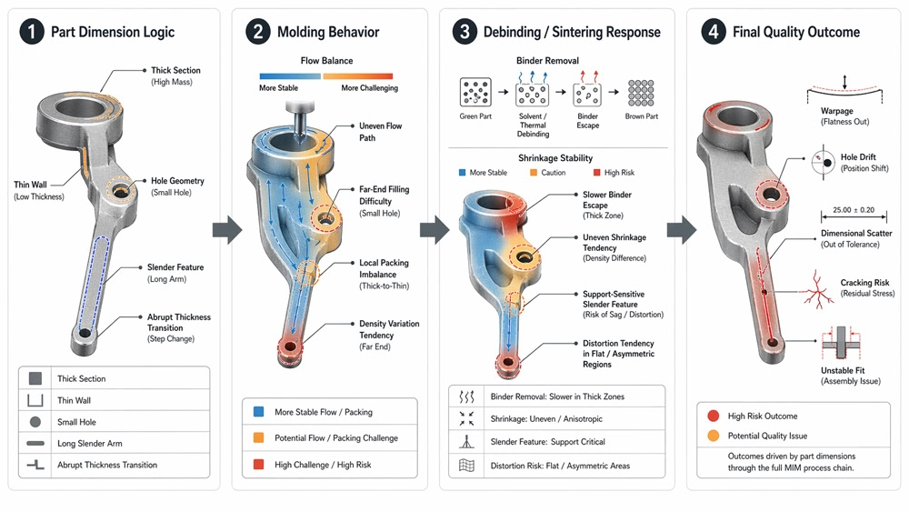
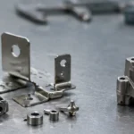
Figure 1. Part dimensions influence the full MIM process chain. Wall thickness, feature size, and section transitions affect filling behavior first, then binder removal, shrinkage stability, and final dimensional quality.
How Dimensions Influence the Full MIM Process Chain
1. During Molding
Dimensions control flow length, pressure transfer, packing effectiveness, and whether thin downstream features can fill consistently. Long thin sections, narrow ribs, and abrupt section changes often increase the risk of density imbalance, incomplete feature definition, and unstable green part handling.
If you are reviewing where dimensional instability starts in early processing, see our MIM injection molding page for the molding-stage link between feedstock flow, cavity filling, gate logic, and green part quality.
2. During Debinding
Dimensions also affect how easily binder can leave the part. Thick sections, enclosed mass, and poor escape paths make binder removal slower and less forgiving. In practice, heavy cross-sections and abrupt mass concentration often create higher risk than many buyers expect.
For a deeper process explanation, see our guide to the MIM debinding process, where binder removal behavior is treated as preparation for stable sintering rather than as an isolated step.
3. During Sintering
After debinding, size distribution influences shrinkage consistency, support conditions, and deformation tendency. Long unsupported spans, thin flat surfaces, and asymmetrical mass distribution are common drivers of warpage, bending, and positional drift. For dimensions that cannot remain stable as-sintered, the drawing should identify whether shrinkage compensation, sizing, or secondary machining is the safer route.
4. During Final Inspection and Assembly
Many parts do not fail because the nominal dimensions are impossible. They fail because the critical tolerances are placed on features that are unstable as-sintered. Hole position, flatness, straightness, and slot width become difficult when their reference geometry moves during shrinkage. Final dimensional planning should therefore connect the drawing to MIM tolerance planning and inspection and testing.
Which Dimensional Details Most Often Affect Final Quality
The most important dimensional review points in MIM are rarely the overall outside dimensions alone. In real projects, the highest-risk dimensions are usually functional dimensions located on unstable features: holes near free edges, slots in weak ligaments, flatness requirements on thin plates, or assembly datums placed on long unsupported geometry.
Dimensional Detail
Why It Matters in MIM
Typical Quality Risk
Wall thickness
Controls filling, debinding speed, and local shrinkage behavior.
Short shot, local density variation, cracking, warpage, unstable dimensions.
Thickness transitions
Large thick-to-thin jumps create different local process responses inside one part.
Distortion, stress concentration, dimensional drift, local weakness.
Length and slenderness
Long unsupported features are more likely to bend or twist during sintering.
Small openings and narrow ligaments are sensitive to fill stability and shrinkage movement.
Hole drift, slot spread, poor roundness, edge deformation, fit issues.
Large flat areas
Flat geometry offers less resistance to nonuniform shrinkage.
Flatness failure, bowing, unstable datum surfaces.
Critical dimensions on unstable features
Not every feature is equally safe to control as-sintered, especially when the tolerance is placed on a feature that moves during shrinkage.
Batch scatter, rework, heavy inspection burden, secondary machining cost, or late drawing changes.
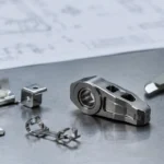
Figure 2. Good dimensional logic in MIM is not only about keeping the part small. It is about controlling wall thickness, smoothing section transitions, supporting slender features, and placing critical dimensions on more stable geometry.
Wall Thickness
Wall thickness is one of the first dimensions that should be reviewed. Thick sections are not only a cost issue. They also slow binder removal and make local shrinkage less forgiving. Very thin sections can create a different problem: incomplete fill, weak green parts, and fragile downstream handling. In most MIM projects, a more uniform wall pattern matters more than simply pushing for the thinnest possible section.
Thickness Transitions
Even when each individual wall looks acceptable, abrupt transitions between thick and thin regions can still create instability. A thick boss attached to a thin arm, or a heavy flange tied to a narrow section, often behaves like two different shrinkage bodies connected in one part. That mismatch is a common source of distortion and dimensional scatter.
Long, Slender, or Unsupported Features
A long part is not automatically unsuitable for MIM, but long unsupported geometry is much more sensitive during sintering. Tabs, fork arms, narrow frames, and slender lever-like features can survive molding but still move later. Length only becomes meaningful when combined with local thickness, support logic, and mass balance.
Holes, Slots, and Windows
Small holes and slots should not be judged by nominal size alone. The more important question is how much stable material remains around them after shrinkage. Deep or narrow openings near free edges, or slots that leave thin ligaments on both sides, are common sources of final fit problems. When necessary, the right engineering decision is to leave a critical bore or hole to secondary machining rather than forcing it to hold fully as-sintered.
Large Flat Surfaces and Asymmetrical Mass Distribution
Broad thin surfaces with local pads, steps, or windows often create flatness problems. Likewise, asymmetrical mass distribution can drive one side of the part to shrink differently from the other. These cases often look acceptable in early review but become much more visible at production scale.
Typical Quality Failures Caused by Poor Dimensional Logic
Many MIM defects are not random. They follow a fairly repeatable dimensional logic. When a geometry contains thickness imbalance, long unsupported zones, small openings in weak ligaments, or large flat areas, the final quality problem is usually one of the following: distortion, dimensional drift, poor assembly fit, unstable flatness, or increased secondary finishing cost.
Case 1: Thick Boss + Thin Arm
A lever-like part may look easy to mold, but once a thick mounting boss is tied to a long thin arm, the geometry becomes much harder to shrink consistently. The boss and arm do not behave the same way in debinding and sintering. The result is often angular error, hole position drift, or a mismatched tip location.
Case 2: Long Slot + Coaxial Holes
A fork-shaped part with a narrow slot and two position-critical holes often creates trouble because the slot leaves thin walls that can move relative to each other. The final inspection problem may show up as slot spread, inward collapse, or a loss of positional relationship between holes.
Case 3: Flat Plate + Local Pads
A part with a broad flat area and several thicker local pads may pass early molding checks but still bow after sintering. In this case, the problem is not only size. It is the uneven mass distribution across a weak flat body.
These examples illustrate a broader rule: in MIM, the final defect often appears later than the dimensional design mistake that caused it.
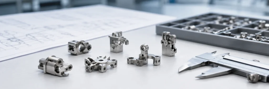
Figure 3. Many final MIM defects can be traced back to dimensional logic. Thick sections, weak ligaments, flat asymmetrical areas, and long unsupported features often lead to distortion, cracking, hole drift, or unstable fit after sintering.
What Size Conditions Are More Suitable for MIM
MIM is usually strongest when the part is small to medium in overall size, geometrically complex, and produced at volumes that justify tooling. But even more important than overall size is whether the dimensional logic supports stable manufacturing.
Parts are usually better suited to MIM when they combine these conditions:
Wall thickness is reasonably controlled and not dominated by abrupt thick-to-thin jumps.
Critical features are not all concentrated on long unsupported geometry.
Hole sizes, slots, and fine details are balanced by enough surrounding support.
Large flat surfaces are limited or structurally balanced.
Not every critical tolerance is forced into the as-sintered condition.
Material selection also interacts with dimensional behavior. If you are comparing alloy choices against tolerance, strength, corrosion resistance, or post-processing needs, see our guide to MIM materials. If the issue is design feasibility rather than alloy choice, use our DFM for MIM guide to review the drawing before tooling.
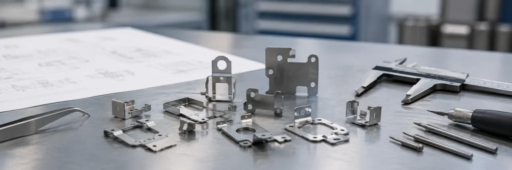
Figure 4. A part is not suitable for MIM just because it fits within a general size range. The better evaluation is whether its dimensions support stable filling, debinding, shrinkage control, and an economical tolerance plan.
Practical DFM Checklist Before Tooling
Before approving a MIM design, engineers and buyers should review more than the nominal dimensions on the print. The dimensional questions below are often more useful than a simple pass/fail check against a generic size range.
Check 1: Is wall thickness reasonably uniform, or are there major local mass concentrations?
Check 2: Are thick-to-thin transitions gradual, or do they create obvious shrinkage imbalance?
Check 3: Are long features structurally supported during sintering, or are they free to bend?
Check 4: Do holes and slots leave enough stable material around them after shrinkage?
Check 5: Are the most critical dimensions assigned to the most stable features?
Check 6: Which dimensions should remain as-sintered, and which should be machined or otherwise corrected later?
Check 7: Has gate logic and support logic been discussed early with the MIM supplier?
Check 8: Is the quality target realistic for the chosen material, geometry, and production route?
For standards language and material specification references, it is good practice to review relevant MPIF standards rather than relying on broad capability claims alone. For a real production example showing how geometry-sensitive features may require stronger process support, see this industry example from MPIF.
Drawing review note: If several checklist items apply to your part, the next step should not be a simple “MIM yes or no” answer. The safer review is to separate dimensions that can remain as-sintered from dimensions that may need mold compensation, sizing, CNC finishing, or inspection control. You can submit your drawing for MIM review when these decisions are not clear from the print alone.
Practical Signs That Part Dimensions Need MIM Engineering Review
Some dimensional risks are easier to find before tooling than after sampling. The signs below do not mean the part is unsuitable for MIM, but they do indicate that the drawing needs engineering review before mold design, tolerance commitment, or quotation finalization.
Practical Sign on the Drawing
Why It Needs Review
Likely Engineering Decision
A thick boss connects to a thin arm
The boss and arm may shrink differently, creating angular error or hole position drift.
Review wall transition, support logic, gate location, and whether a local tolerance needs machining.
A long slot leaves weak ligaments
Thin ligaments can spread, collapse, or move during sintering.
Check slot width, ligament support, inspection datum, and possible post-sinter correction.
Critical holes are close to free edges
Edge movement during shrinkage can shift hole position or roundness.
Decide whether the hole can be molded as-sintered or should be finished after sintering.
Large flat areas include local pads or steps
Uneven mass on a thin flat area can drive bowing and unstable flatness.
Review mass balance, sintering support, flatness tolerance, and inspection method.
All functional tolerances are required as-sintered
Some tolerances may be realistic after sintering, while others may increase rework and inspection burden.
Separate as-sintered dimensions from dimensions requiring sizing, machining, or tighter inspection control.
A long unsupported feature controls assembly fit
Even small bending or twist can create assembly mismatch.
Review straightness, datum strategy, fixture support, and the total tolerance stack.
Practical takeaway: Dimensional review should happen before tooling, not after the first trial parts. If the drawing contains several of these signs, use Submit Drawing for Review so the MIM route, tolerance plan, and secondary operation strategy can be checked together.
Related Quality Factors in This MIM Part Quality Series
Part dimensions are only one quality driver. Final MIM part quality is usually controlled by the combined effect of part design, material selection, mold design, feedstock behavior, injection molding, debinding, sintering, and inspection. Use the related pages below to review the full quality chain without mixing the page sovereignty of each topic.
Review how dimensional inspection supports tolerance confirmation, functional fit, and production quality control.
FAQ: Part Dimensions and MIM Quality
Why do part dimensions affect MIM quality so much?
Because dimensions directly change flow behavior in molding, binder removal paths in debinding, and shrinkage stability in sintering. In MIM, dimensional design affects process behavior all the way from green part formation to final inspection.
Is a thicker section always safer in MIM?
No. Thicker sections may improve local stiffness, but they often slow debinding and increase the risk of nonuniform shrinkage. In many cases, a more uniform section is safer than a locally overbuilt one.
Which dimensional features most often cause warpage in MIM?
Common warpage drivers include large flat areas, asymmetrical mass distribution, long unsupported features, and abrupt thick-to-thin transitions. These conditions make shrinkage less balanced during sintering.
Are small holes and thin walls always suitable for MIM?
Not automatically. Small features may be technically possible, but suitability depends on flow path, local support, remaining ligament thickness, material system, and the required final tolerance. Some critical holes are better left for post-sinter machining.
How do you know whether a part is dimensionally suitable for MIM?
A suitable MIM part is not judged by overall size alone. The better test is whether the geometry supports stable filling, effective binder removal, predictable shrinkage, realistic as-sintered tolerances, and an economical total process route.
Conclusion
In MIM, dimensions do not simply describe the part. They shape the process. A part may sit inside a published size window and still perform poorly if its wall thickness, transitions, holes, flat surfaces, or unsupported spans are dimensionally unbalanced.
The most reliable MIM parts are not the ones pushed to every geometric limit. They are the ones whose dimensions are designed for stable filling, cleaner debinding, more predictable shrinkage, and realistic quality control after sintering. When the dimensional risk is unclear, the most useful next step is an early drawing review rather than waiting until tooling or trial production exposes the issue.
Need a Dimension Review Before MIM Tooling?
If your drawing includes thick-to-thin transitions, small holes, long unsupported features, flatness-sensitive surfaces, or critical dimensions that may be difficult to hold as-sintered, an early MIM engineering review can help separate stable dimensions from features that may need sizing, secondary machining, or design adjustment.
Send the drawing before tooling so we can review dimensional stability, shrinkage risk, as-sintered tolerance expectations, inspection requirements, and possible post-sinter operations together.