
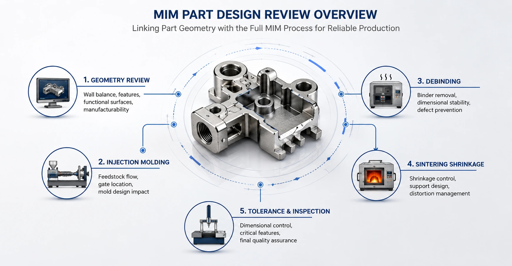
A design that looks acceptable in CAD may still create risks during injection molding, green part handling, debinding, sintering, or final inspection.
Quick Engineering Summary for MIM Part Design
Before tooling, the key question is whether the part geometry can survive the full MIM process chain without creating avoidable molding, debinding, sintering, tolerance, or inspection problems. For machined, stamped, or assembled parts, this is also a design-conversion review: the goal is not to copy every CNC feature into MIM, but to decide whether the geometry can be redesigned into a moldable, sinterable, inspectable metal component. This page helps you decide whether the overall part geometry is suitable for MIM before moving into detailed wall thickness, mold, gate, tolerance, or full DFM review.
What MIM Part Design Really Means
MIM part design means reviewing a component as a full manufacturing system, not as an isolated 3D shape. In practice, the design must pass through several linked stages: feedstock injection, demolding, green part handling, debinding, sintering shrinkage, possible secondary machining, surface finishing, and final inspection.
A part may look suitable in CAD but still create production risk if it has abrupt wall transitions, unsupported thin features, hidden thick sections, unrealistic tolerances, or critical surfaces located where gates, ejector marks, parting lines, or support marks may appear.
From a design review perspective, the strongest MIM candidates are usually small, complex metal parts where geometry adds value. MIM can be useful when multiple machined, stamped, or assembled features can be consolidated into one molded metal component. When the starting point is a machined part, review CNC to MIM conversion as a design evaluation, not a direct copy of the original machining drawing. The Metal Injection Molding Association explains that MIM provides plastic-injection-like design freedom while producing a metal component, which is why shape complexity, material performance, production quantity, and component cost should be considered together.
| MIM Part Design Review Question | Why It Matters |
|---|---|
| Is the part small and complex enough for MIM? | MIM value increases when complexity replaces machining or assembly. |
| Are wall sections reasonably balanced? | Unbalanced sections may increase shrinkage variation, void risk, or distortion. |
| Are holes, slots, and undercuts moldable? | These features affect core pins, slides, ejection, flash, and mold cost. |
| Are critical surfaces clearly marked? | Gate position, parting line, ejector marks, and support surfaces must be planned. |
| Can the part be supported during sintering? | Unsupported spans, thin frames, and flat areas may distort. |
| Are tolerances realistic for the process? | Critical dimensions may need secondary machining or a specific inspection plan. |
When a Part Is a Good Candidate for MIM
A part is usually a good candidate for MIM when complexity, production volume, material performance, and dimensional requirements align. MIM is not automatically the best option for every metal part. It is most effective when the geometry would be costly to machine, difficult to stamp, hard to cast cleanly, or inefficient to assemble from multiple small parts.
Good MIM candidates often include small metal components with thin walls, cross holes, slots, bosses, ribs, undercuts, splines, irregular contours, micro features, or integrated functional details. Complex features can strengthen the rationale for MIM when the business and material conditions also fit.
Replacing a machined part with MIM is usually strongest when the redesign consolidates features, reduces repeated machining operations, or removes separate assembly steps while still allowing realistic mold release, sintering support, tolerance planning, and inspection access.

MIM is most suitable for small, complex, multi-feature metal parts where molded geometry can reduce machining, assembly, or secondary operations.
| Part Condition | MIM Suitability | Design Review Note |
|---|---|---|
| Small, complex, multi-feature metal part | High | Strong candidate for MIM feasibility review. |
| Simple block, plate, or straight shaft | Low | CNC, stamping, casting, or PM may be more economical. |
| Multiple holes, slots, or undercuts | Medium to High | Tooling direction, core pins, slides, and flash risk must be reviewed. |
| Large thick solid section | Low to Medium | Debinding time, sintering shrinkage, and distortion risks increase. |
| Critical functional surfaces | Medium to High | Gates, parting lines, ejector marks, and inspection datums must be planned early. |
| Tight tolerance required on every dimension | Medium to Low | Critical dimensions should be separated from general dimensions. |
| Medium to high repeat production | High | Tooling investment is easier to justify when production volume is sufficient. |
| Low-volume development part with unstable design | Low to Medium | CNC or prototype routes may be better before committing to MIM tooling. |
A common mistake is treating MIM as a direct replacement for CNC machining without changing the design. A machined part often has features created by cutting tools, whereas a MIM part must be shaped by injection molding and then controlled through sintering shrinkage. If the project is comparing machining and MIM, review MIM vs CNC machining and CNC to MIM conversion before deciding which features should remain as-molded, which dimensions need secondary machining, and which cost drivers should be checked in MIM design for cost.
Key Geometry Factors in MIM Part Design
The strongest part design reviews look at geometry as an interacting system. This is especially important when converting a machined, stamped, or assembled part into a MIM component, because cutting-tool features may need to become moldable features. Wall balance, holes, slots, undercuts, ribs, bosses, functional surfaces, datum areas, and support areas should be reviewed together before tooling.

The most important MIM part design risks are not isolated features, but how multiple features interact through molding, debinding, sintering shrinkage, and inspection.
Overall Part Size, Mass, and Complexity
The first review point is the relationship between part size, mass, and complexity. MIM is strongest when a component is small enough to be molded and sintered efficiently, but complex enough to justify tooling and process development.
A large simple part may not be a good MIM candidate because it does not use the main advantage of the process. A very thick part may create debinding and sintering challenges because binder removal and shrinkage behavior become harder to control. A very thin or long unsupported part may be difficult to handle as a green part and may distort during sintering.
In production, the practical size limit depends on material, feedstock, tool design, debinding route, sintering support, tolerance expectations, and the supplier’s process capability. Fixed “maximum part size” claims should not be used as universal design rules.
Wall Balance and Section Transitions
Wall balance is one of the first geometry checks in MIM part design. Uneven wall sections can affect feedstock flow during injection molding, binder removal during debinding, and shrinkage consistency during sintering. Thick areas may shrink differently from thin areas, especially when they connect abruptly.
A design engineer should look for sudden thick-to-thin transitions, heavy bosses, isolated thick pads, and thick sections hidden inside cosmetic shapes. The goal is not always to make every area identical. The goal is to avoid unnecessary mass concentration and to create smoother transitions where the function allows it.
For deeper rules on thickness distribution, thick-section risk, coring strategy, and transitions, see the dedicated page on MIM wall thickness design.
Holes, Slots, and Undercuts
Holes, slots, and undercuts can be valuable in MIM because they allow functional geometry to be molded into the part. They can reduce machining, drilling, or assembly operations. However, these features also introduce tooling and inspection risk.
The review should consider feature direction, depth, opening access, core pin strength, slide requirements, possible flash locations, and whether the feature can be measured after sintering. A cross hole that looks simple on the drawing may require additional mold action. A blind slot may create filling, venting, or inspection limitations.
For detailed moldability review, continue to holes, slots and undercuts in MIM.
Ribs, Bosses, Thin Features, and Local Details
Ribs, bosses, thin walls, logos, markings, and local functional details can improve the value of MIM by integrating multiple features into one metal part. They can also create localized risk.
A tall thin rib may fill poorly or deform after ejection. A large boss may create a thick mass that shrinks differently from the surrounding wall. A sharp logo or marking may be difficult to mold cleanly if placed on a functional or cosmetic surface. Local details should be reviewed not only for shape, but also for mold release, filling, green part strength, and sintering stability.
Functional Surfaces, Critical Dimensions, and Datum Areas
MIM part design should clearly identify functional surfaces before tooling. These may include sealing faces, bearing seats, sliding surfaces, rotational features, electrical contact areas, magnetic surfaces, locking features, or cosmetic zones.
A supplier should not have to guess which surfaces are critical. If a functional area is not marked, the gate, parting line, ejector mark, or sintering support mark may be placed in a location that creates assembly or inspection problems later.
Critical surfaces should be reviewed together with MIM gate design and MIM tolerances. Specifying tight tolerances everywhere often increases cost and rejection risk without improving function.
How Part Design Affects Molding, Debinding, and Sintering
MIM part design affects every process stage. A feature that looks minor in CAD may create issues during filling, ejection, binder removal, sintering shrinkage, or inspection.
MIM uses fine metal powder mixed with binder to form feedstock. The feedstock is injection molded into a green part, debound to remove binder, and sintered into a dense metal component. Material specifications such as ASTM B883 are relevant to ferrous MIM materials, but material standards should not be treated as universal geometry rules for every MIM part design.

MIM design issues rarely stay in one process step; the same geometry problem can become a molding defect, debinding risk, sintering distortion, or inspection disagreement.
| Part Design Factor | Injection Molding Impact | Debinding / Sintering Impact | Review Action |
|---|---|---|---|
| Uneven wall thickness | Flow imbalance, weld line, short shot risk | Non-uniform shrinkage or distortion | Review wall transitions and mass distribution. |
| Deep blind hole | Core pin, venting, and demolding concern | Cleaning and inspection difficulty | Check feature direction and access. |
| Long unsupported span | Ejection and green part handling risk | Warpage or sagging risk | Review sintering support surfaces. |
| Sharp internal corner | Stress concentration and flow hesitation | Crack initiation or distortion risk | Add radius where the function allows it. |
| Critical cosmetic surface | Gate, parting line, or ejector mark concern | Surface acceptance issue after finishing | Mark cosmetic and functional zones clearly. |
| Tight tolerance stack-up | Mold correction and inspection challenge | Post-sintering variation may exceed function | Separate critical dimensions from general tolerances. |
| Thick local boss | Filling and cooling imbalance | Slow debinding and local shrinkage difference | Consider coring or geometry adjustment. |
For deeper background on process-related quality risk, see how injection molding affects MIM part quality and debinding and sintering quality risks.
MIM Part Design Risks to Check Before Tooling
Tooling is one of the most important commitment points in a MIM project. Before mold construction, the drawing should be reviewed for geometry risks that may affect molding stability, sintering distortion, secondary operations, and inspection agreement.
| Risk Area | What to Check | Why It Matters |
|---|---|---|
| Wall transition | Sudden thick-to-thin changes | May cause shrinkage imbalance, void risk, or local distortion. |
| Unsupported geometry | Long arms, thin frames, flat plates, cantilever features | May distort during green handling or sintering. |
| Side features | Cross holes, side slots, internal undercuts | May require slides, core pins, or complex mold actions. |
| Functional surfaces | Sealing, bearing, sliding, contact, and cosmetic areas | Gate, parting line, and support locations must be planned. |
| Critical dimensions | Which dimensions truly control function | Avoid unnecessary tight tolerance on non-critical areas. |
| Post-machining areas | Threads, bearing seats, sealing faces, datum faces | Secondary operations should be planned before tooling. |
| Datum and inspection | Measurement access and functional datum strategy | Prevent inspection disagreement after trial production. |
| Surface finishing zones | Polishing, coating, passivation, heat treatment, or cosmetic requirements | Surface treatment may change appearance or dimensions. |
For a deeper list of avoidable issues, continue to common MIM design mistakes.
Composite Field Scenario for Engineering Training: Thin Frame Distortion After Sintering
What problem occurred: A thin frame-like MIM part showed distortion after sintering. The CAD model appeared symmetrical, but the flatness-sensitive area could not remain stable through production trials.
Why it happened: The part had long unsupported spans and uneven local mass near mounting features. During sintering shrinkage, different sections moved differently because the part did not have a stable support strategy.
What the real system cause was: The issue was not only the sintering process. The design did not identify flatness-sensitive areas early, and the tooling and sintering support plan were not reviewed together before mold construction.
How it was corrected: The design was reviewed for support surfaces, wall transitions, and functional datums. Non-critical geometry was adjusted to improve stiffness, and the support strategy was planned around the functional flatness area.
How to prevent recurrence: Long spans, thin frames, and flatness-critical surfaces should be reviewed before tooling. Sintering support requirements should be considered as part of part design, not treated as a late production adjustment.
For more detail, review sintering support for MIM parts.
Pre-Tooling MIM Part Design Checklist
Before mold construction, the design team should confirm that the part geometry, functional surfaces, tolerance plan, inspection method, and expected production route are aligned. This checklist is intended for early engineering screening, not as a replacement for drawing-based DFM review.
Check whether the part is small, complex, and repeat-produced enough to justify MIM tooling and process development.
Identify thick sections, sudden transitions, heavy bosses, and areas that may cause shrinkage imbalance or distortion.
Separate sealing faces, bearing seats, sliding surfaces, cosmetic zones, electrical contacts, or assembly-control areas.
Review feature direction, core pin strength, slide requirements, flash risk, demolding, and inspection access.
Avoid placing gates, parting lines, ejector marks, or support marks on functional or high-visibility surfaces.
Check long spans, thin frames, flatness-sensitive surfaces, cantilever areas, and possible setter contact zones.
Classify critical dimensions, general dimensions, post-machining dimensions, and reference dimensions before quoting.
Clarify datums, CMM needs, gauges, thread checks, visual criteria, surface finish requirements, and acceptance priorities.
When MIM Part Design Should Be Reconsidered
Not every metal component should be converted to MIM. A responsible MIM design review should also identify cases where CNC machining, stamping, die casting, casting, forging, or pressed powder metallurgy may be more suitable.
The part design should be reconsidered when the geometry does not use the strengths of MIM, when tooling cannot be justified, or when the tolerance and functional requirements would force excessive secondary machining.
| Requirement | Concern | Possible Direction |
|---|---|---|
| Very simple geometry | MIM tooling may not be justified | CNC machining, stamping, PM, or casting may be reviewed. |
| Very low annual volume | Tooling and development cost may be hard to amortize | CNC or prototype routes may be more practical. |
| Large solid section | Debinding and sintering risks may increase | Casting, forging, or machining may be more suitable. |
| Tight tolerance on most surfaces | Secondary machining may dominate cost | Use CNC or a hybrid MIM + machining strategy only where justified. |
| Large flat thin plate | Sintering distortion risk may be high | Stamping or machining may provide better stability. |
| Critical surface cannot accept gate, parting line, or support marks | Tooling and finishing complexity increases | Rework the surface plan or consider another process. |
| Material requirement is not defined | Performance cannot be validated early | Confirm material specification before DFM. |
Composite Field Scenario for Engineering Training: CNC Part Converted to MIM Without Tolerance Separation
What problem occurred: A CNC-machined component was redesigned for MIM, but the drawing kept tight machining-style tolerances on nearly every dimension.
Why it happened: The original drawing was created for subtractive machining. It did not distinguish functional dimensions from non-critical geometry.
What the real system cause was: The issue was not only tolerance capability. The project lacked a tolerance strategy. Critical surfaces, datums, secondary machining areas, and inspection methods were not separated before tooling review.
How it was corrected: The drawing was updated to classify critical dimensions, general dimensions, post-machining areas, and inspection datums. Only function-critical features were kept under tighter control.
How to prevent recurrence: Before converting CNC to MIM, the design team should review which dimensions affect function, which surfaces can remain as-sintered, and which features may require secondary machining or sizing.
For related dimensional planning, see MIM shrinkage compensation and MIM tolerances.
MIM Part Design Review Matrix
The following matrix helps design engineers decide which part features need deeper review and which related MIM design guide page should be used for the next step.
| Design Feature | Review Priority | Main Risk | Related Guide Page |
|---|---|---|---|
| Overall part geometry | High | Wrong process selection or poor MIM fit | Current page |
| Wall thickness | High | Shrinkage imbalance, voids, distortion | Wall Thickness Design |
| Holes and slots | High | Tooling, flash, demolding, inspection risk | Holes, Slots and Undercuts |
| Undercuts | High | Slides, mold cost, ejection risk | Holes, Slots and Undercuts |
| Gate-sensitive areas | Medium to High | Gate mark, flow imbalance, cosmetic issue | Gate Design |
| Long unsupported features | High | Sintering distortion | Sintering Support |
| Critical dimensions | High | Tolerance, datum, and inspection risk | MIM Tolerances |
| Shrinkage-sensitive geometry | High | Mold compensation and dimensional variation | Shrinkage Compensation |
| Tight cost target | Medium | Over-complex tooling or excessive machining | Design for Cost |
| Full project review | High | Missed manufacturability risk | DFM for MIM |
Critical Dimensions, Datums, and Inspection Strategy
A MIM part design review should not treat every dimension as equally critical. Before tooling, the drawing should separate functional dimensions, general dimensions, reference dimensions, post-machining areas, and inspection datums so the supplier can plan mold compensation, sintering control, secondary operations, and final acceptance.
| Drawing / Inspection Item | What to Define | Why It Matters for MIM |
|---|---|---|
| Functional dimensions | Fits, positions, sealing faces, bearing seats, locking features, assembly-control areas | These dimensions may need tighter process control, secondary machining, sizing, or a dedicated inspection method. |
| General dimensions | Non-critical external shapes, support features, non-functional contours | Over-tightening non-critical dimensions increases cost and rejection risk without improving function. |
| Datums | Primary, secondary, and tertiary references used for measurement and assembly | Unclear datums can create inspection disagreement after sintering or secondary machining. |
| Post-machining zones | Threads, precision holes, bearing surfaces, sealing surfaces, flat datum faces | These zones should be planned before mold construction so enough stock and access are available. |
| Inspection method | CMM, gauges, thread gauges, pin gauges, visual criteria, surface finish checks | The inspection method should match the functional requirement and realistic production control route. |
| Cosmetic and contact surfaces | Areas that cannot accept gate marks, ejector marks, parting lines, support marks, or polishing variation | These areas affect gate planning, mold layout, support strategy, and surface finishing decisions. |
Drawing Information Needed for MIM Part Design Review
A MIM part design review is most useful when the supplier receives enough technical information to understand the function, risks, and production target. A 3D model alone is not enough. A 2D drawing without functional notes may also be incomplete.
| Information Needed | Why It Helps |
|---|---|
| 2D drawing with tolerances | Identifies critical and non-critical dimensions. |
| 3D CAD file | Helps review geometry, wall sections, feature direction, and moldability. |
| Material requirement | Affects feedstock selection, sintering route, strength, corrosion resistance, wear, or magnetic behavior. |
| Estimated annual volume | Helps judge tooling feasibility and production strategy. |
| Functional surfaces | Helps protect critical areas from gates, parting lines, ejector marks, and support marks. |
| Assembly requirements | Helps define datums, fits, and inspection priorities. |
| Surface finish or post-treatment needs | Helps plan secondary operations, polishing, coating, passivation, or heat treatment. |
| Current manufacturing method | Helps evaluate whether MIM can reduce machining, assembly, or cost. |
| Known failure or cost issue | Helps focus DFM review on the real project problem. |
| Inspection requirements | Helps align supplier capability with acceptance criteria. |
If your part has thin walls, complex holes, undercuts, critical cosmetic surfaces, tight assembly dimensions, or high machining cost, it should be reviewed before mold construction.
Send Your Drawing for MIM Part Design Review
If your part includes thin walls, holes, slots, undercuts, complex functional surfaces, tight assembly dimensions, or high CNC machining cost, submit the drawing before tooling. A drawing-based review can help confirm whether the part geometry is suitable for MIM and what should be adjusted before mold investment.
Please provide:
- 2D drawing with tolerances;
- 3D CAD file;
- material requirement;
- estimated annual volume;
- critical dimensions, datums, and functional surfaces;
- surface finish or post-treatment requirements;
- assembly or application background;
- current process problem if replacing CNC, casting, stamping, or assembly.
The engineering review can help evaluate process suitability, wall balance, moldability, gate-sensitive areas, sintering support, shrinkage risk, tolerance strategy, secondary operations, inspection planning, and production feasibility before mold investment.
Standards, Engineering Review, and Practical Limits
MIM part design should be reviewed together with material selection, tolerance requirements, tooling strategy, sintering control, inspection method, and production feasibility. Industry references can guide the discussion, but they should not replace project-specific DFM review.
The MIMA Design Center is useful for understanding why MIM can support complex metal part geometry, part consolidation, and functional features. However, design freedom still needs to be checked against moldability, debinding behavior, sintering shrinkage, support strategy, and inspection requirements.
MPIF Standard 35-MIM covers common materials used in metal injection molding with explanatory notes and definitions. It is most useful when material specification and engineering property expectations are being discussed, not as a universal geometry rulebook.
ASTM B883 is relevant to ferrous metal injection molded materials and should be used as a material specification reference where applicable. It should not be used alone to decide wall thickness, gate location, undercut feasibility, sintering support, or dimensional tolerance strategy.
Final design recommendations should be confirmed through project-specific DFM review using the customer’s drawing, 3D model, material requirement, tolerance specification, functional surfaces, surface finish needs, inspection criteria, and expected production volume.
FAQs About MIM Part Design
What makes a part suitable for MIM design?
A suitable MIM part is usually small, complex, multi-featured, and intended for repeat production. The part should use MIM’s strengths, such as molded holes, slots, ribs, bosses, undercuts, fine details, or assembly consolidation. The design should also be reviewed for wall balance, sintering support, material selection, tolerance requirements, and secondary operations before tooling.
Can a CNC machined part be directly converted to MIM?
Not usually. A CNC part is designed around cutting tools, while a MIM part must pass through injection molding, green part handling, debinding, and sintering shrinkage. Before conversion, the drawing should be reviewed for wall sections, holes, undercuts, critical surfaces, tolerances, datums, and post-machining requirements.
How is MIM part design different from plastic injection molding design?
MIM part design uses some moldability concepts similar to plastic injection molding, but the molded green part must later pass through debinding and high-shrinkage sintering to become a dense metal component. This means wall balance, support surfaces, shrinkage compensation, material behavior, and inspection strategy must be reviewed more carefully than in a simple plastic part design comparison.
Which part features need special review before MIM tooling?
Thin walls, thick local sections, cross holes, deep slots, undercuts, long unsupported spans, sharp corners, cosmetic surfaces, sealing faces, bearing seats, and tight tolerance features should be reviewed before tooling. These features may affect mold design, gate location, ejection, sintering distortion, inspection, or secondary machining.
Does MIM allow undercuts and internal features?
MIM can support complex features, including some undercuts and internal details, but feasibility depends on mold action, core pin strength, feature direction, demolding, flash control, and cost. Some undercuts are practical; others may require slides, redesign, or secondary machining.
How does part design affect sintering distortion?
Sintering distortion is influenced by wall imbalance, uneven mass, long unsupported spans, flatness-sensitive areas, thin frames, and unstable support surfaces. A geometry that looks acceptable in CAD may still move during sintering if shrinkage and support are not considered during design review.
Do all MIM dimensions need tight tolerances?
No. Tight tolerances should be applied only to dimensions that affect function, assembly, sealing, rotation, positioning, or inspection. General dimensions should be controlled according to realistic MIM capability, while critical features may need secondary machining, sizing, or a dedicated inspection strategy.
How should critical dimensions be marked for a MIM part design review?
Critical dimensions should be separated from general dimensions and linked to functional surfaces, assembly requirements, datum references, and inspection methods. If a dimension controls sealing, sliding, rotation, fit, positioning, or safety-related assembly, it should be clearly marked so the MIM supplier can review tolerance strategy, secondary machining, and measurement feasibility before tooling.
What files should I provide for a MIM part design review?
Provide a 2D drawing with tolerances, a 3D CAD file, material requirements, estimated annual volume, functional surfaces, surface finish requirements, heat treatment or coating needs, assembly requirements, and any current manufacturing problems. These inputs help the engineering team review manufacturability before tooling.
When should I request a MIM DFM review?
Request a MIM DFM review before mold construction, especially if the part has thin walls, thick local sections, holes, slots, undercuts, critical surfaces, tight assembly dimensions, or high machining cost. Early review helps confirm process suitability, tooling risk, sintering support, tolerance strategy, inspection planning, and secondary operation needs before investment is locked.