Share your drawing, material requirements, annual volume, tolerance needs, or application details. Our engineering team will review your MIM project and respond with technical feedback or a quotation.
Metal injection molding is used in industries that need small, repeatable metal parts with geometry that is difficult, slow, or wasteful to machine. Typical MIM industries include medical and dental devices, automotive components, electronics, wearables, locks, industrial tools, watches, eyewear, consumer hardware, and selected aerospace-related assemblies. This article explains industry applications and part suitability; it …
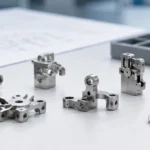
Metal injection molding is used in industries that need small, repeatable metal parts with geometry that is difficult, slow, or wasteful to machine. Typical MIM industries include medical and dental devices, automotive components, electronics, wearables, locks, industrial tools, watches, eyewear, consumer hardware, and selected aerospace-related assemblies. This article explains industry applications and part suitability; it is not a market-size forecast or a general MIM market report. MIM is not selected only because a part looks complex. It becomes practical when the part size, material, annual volume, tolerance plan, and secondary operations all fit the process window. The strongest metal injection molding applications are small MIM parts with fine features, internal shapes, bosses, slots, miniature mechanisms, or difficult-to-machine alloys. The weak applications are large parts, long flat parts, very thick sections, mirror-cosmetic surfaces, or datum-critical dimensions that cannot tolerate sintering shrinkage variation. For a good manufacturing decision, engineers should evaluate MIM materials, MIM tolerances, tooling cost, debinding risk, sintering shrinkage, density, surface finish, and post-sinter machining before approving the process or submitting a drawing for review.
MIM is commonly used for small repeatable metal parts in medical, automotive, electronics, industrial, and wearable applications.
Why Different Industries Use Metal Injection Molding
Different industries use metal injection molding when a small metal part has enough repeated demand, geometry complexity, and material requirement to justify tooling and sintering control. The process usually includes metal powder selection, binder system preparation, feedstock mixing, injection molding, debinding, sintering, and secondary operations when required. The main engineering value is not simply “complex shape.” It is the ability to consolidate fine features, internal shapes, bosses, slots, teeth, hinges, or compact mechanisms into a repeatable near-net-shape part while reducing unnecessary machining on non-critical surfaces.
ASTM B883 is relevant when ferrous MIM materials are specified because it defines the general material route for metal injection molded ferrous parts, including powder and binder mixing, injection, debinding, sintering, and possible heat treatment. MPIF Standard 35-MIM is relevant because it helps engineers and buyers specify MIM materials with more consistent expectations. These standards matter during quoting, drawing review, material approval, mechanical testing, and production acceptance.
For engineering evaluation, the real question is not only “what industries use MIM parts.” The better question is: “Which industries have small metal parts where MIM geometry, material performance, tooling cost, sintering control, and post-processing make sense together?” Industry references such as the Metal Injection Molding Association and European Powder Metallurgy Association describe MIM as a process used across multiple industrial markets, but final process selection still depends on part geometry and qualification requirements. For market-direction reading, use the MIM industry trends guide; for part-level feasibility, use the MIM application selection guide.
Industry Demand vs MIM Part Suitability
A growing MIM market or strong industry demand does not mean every metal part in that industry should use MIM. Market terms such as medical MIM applications, automotive MIM parts, electronics MIM components, or wearable device MIM parts show where the process is often considered. The manufacturing decision still has to be made at part level: geometry, wall thickness, annual volume, material grade, tolerance strategy, debinding risk, sintering shrinkage, surface finish, and inspection method must all fit together.
Search or Business Signal
What It Tells You
What It Does Not Prove
Best Next Step
MIM market growth
More industries are considering MIM for compact metal components
It does not prove a specific part is moldable or economical
Review part geometry, annual volume, and material route
MIM part quality depends on feedstock control, molding stability, debinding, sintering shrinkage, density, and secondary processing.
Industries That Commonly Use MIM Parts
The industries below should be read as application categories, not as a market-share ranking. Each industry uses MIM for different reasons: medical projects may care about corrosion resistance and cleaning; automotive projects may care about wear, fatigue, and batch stability; electronics and wearable projects may care about miniaturization, assembly fit, and surface treatment. If you need a broader navigation page by industry, see the MIM industries hub. If you need part-level examples, see the metal injection molding applications page.
Medical and Dental Devices
Medical and dental applications often use MIM for small stainless steel, titanium alloy, or application-specific alloy components where geometry, corrosion resistance, repeatability, and validated surface condition matter. Typical examples include surgical instrument components, orthodontic brackets, small jaws, dental tool parts, endoscopic hardware, grasping features, and compact housings.
MIM can be useful in this field because many medical parts are small, detailed, and difficult to machine economically in volume. However, medical MIM parts require stricter control than general industrial hardware. Engineers should review material certification, biocompatibility requirements, passivation, cleaning, burr limits, surface roughness, lot traceability, and inspection method before approving production.
A common engineering mistake is assuming that a medical MIM part can come directly from sintering with every functional surface finished. In a composite field scenario for engineering training, a medical instrument jaw was initially designed as a fully molded MIM component, but the gripping surface did not meet the required contact behavior and edge definition. The real issue was not only surface roughness; the design had mixed near-net-shape geometry with precision functional datums. The correction was to keep the body as a MIM near-net-shape part while adding post-sinter machining on the gripping surface and functional datum. To prevent recurrence, medical projects should separate molded geometry, machined contact surfaces, polished areas, passivated surfaces, and inspection-controlled datums before tooling.
Automotive and Mobility Components
Automotive applications use MIM where small metal parts need stable production volume and repeatable functional geometry. Typical MIM parts may include actuator components, sensor-related hardware, small brackets, locking elements, seat mechanism parts, transmission-related small components, EV hardware, and compact wear parts.
The reason automotive projects consider MIM is usually a combination of geometry consolidation, reduced machining, wear resistance, consistent batches, and cost control at volume. For automotive MIM parts, the key review items are sintering shrinkage control, density, porosity, heat treatment response, fatigue behavior, dimensional stability, and functional gauging.
Automotive projects also show why MIM design guidelines must be reviewed before transferring a machined design into a mold. In a composite field scenario for engineering training, a small automotive bracket had acceptable green part quality but failed final flatness after sintering. The part had one thick boss connected to a long thin arm, so the two areas shrank and cooled differently. The systemic cause was that the CNC design had been moved into MIM without redesigning wall transition, sintering support, gate position, and part orientation. The correction was to smooth the boss transition, change the setter support, and move the critical flatness area away from the highest shrinkage-risk zone. Before quoting automotive MIM parts, wall balance, sintering support, gate location, and possible sizing or machining should be reviewed together.
Electronics, Connectors, and Wearable Devices
Electronics and wearable products often use MIM for hinges, buttons, small structural frames, connector-related parts, shielding components, sensor housings, latch parts, camera-related hardware, smartwatch parts, and compact mechanical interfaces.
These parts often combine small size, assembly fit, thin features, and cosmetic or semi-cosmetic surfaces. MIM can support detailed geometry, but electronics projects often underestimate surface treatment risk. Polishing, PVD, plating, blasting, and passivation can reveal pores, flow marks, parting lines, weld lines, or sintering distortion.
For visible electronics parts, the drawing and quality plan should define cosmetic surfaces, non-cosmetic surfaces, gate area, polishing allowance, acceptable pits, edge rounding limits, inspection lighting, and whether PVD or plating is decorative, protective, or functional. In a composite field scenario for engineering training, a wearable device hinge looked acceptable after sintering and polishing, but after PVD coating, small pits and dark spots became visible. The polishing step had opened near-surface pores, and the PVD coating made them easier to see under reflected light. The systemic cause was that the team approved the MIM part mainly by dimensions and did not define cosmetic zones, pore acceptance, polishing allowance, or pre-PVD inspection. The corrective action was to adjust density control, change polishing steps, and inspect before coating. For future projects, coating route and cosmetic inspection should be part of tool-release review, not an afterthought.
Locks, Security Hardware, and Mechanical Hardware
Lock and mechanical hardware industries use MIM for cams, pawls, levers, latches, buttons, internal linkages, small gears, sliding blocks, and compact mechanical parts with multiple functional faces.
MIM is often considered because lock parts may need complex profiles, local wear resistance, small features, and stable assembly fit. Low-alloy steels, stainless steels, and hardenable stainless grades may be selected depending on strength, corrosion resistance, sliding wear, and surface hardness requirements.
A lock component can pass dimensional inspection but still fail during cycle testing if material hardness, density, surface condition, edge geometry, lubrication, or heat treatment is not suitable. In a composite field scenario for engineering training, a lock cam had correct dimensions but showed early wear during cycling. The selected stainless material had acceptable corrosion resistance but insufficient surface hardness for repeated sliding contact. The real cause was material selection based on appearance and corrosion resistance rather than contact stress and wear mechanism. The correction was to change to a hardenable grade and verify heat treatment hardness. For locks and mechanical hardware, torque transfer, sliding contact, lubrication, hardness, edge condition, and wear testing should be reviewed before final MIM material approval.
Industrial Tools, Power Tools, and Equipment Parts
Industrial tools and equipment may use MIM for small levers, holders, drive parts, wear components, adjustment parts, miniature tool components, pump-related parts, valve-related small parts, and parts with multiple machined-like faces.
The key engineering question is whether the part mainly needs strength, surface hardness, wear resistance, toughness, corrosion resistance, magnetic behavior, or dimensional repeatability. For example, 17-4PH may be suitable when strength and corrosion resistance are both needed. Low-alloy steel may be more suitable when heat treatment response and wear resistance matter more than corrosion resistance.
Industrial parts also need a practical inspection plan. A drawing with many tight tolerances can force unnecessary post-machining and increase cost. During design review, the supplier should separate molded dimensions, sizing dimensions, machined dimensions, and functional gauge dimensions.
Aerospace-Related and High-Specification Assemblies
Aerospace-related assemblies may use MIM for selected small parts where geometry, weight control, and repeatability are valuable. Possible applications include small brackets, sensor housings, actuator components, fastener-related features, secondary hardware, and compact mechanism parts.
These projects require cautious evaluation. The decision should start with material standard, density, microstructure, mechanical testing, traceability, heat treatment, surface condition, and approval process. MIM should not be promoted as a quick replacement for critical aerospace parts without proper qualification.
For high-specification assemblies, the question is not “can the shape be molded?” The real question is whether the supplier can prove material performance, dimensional stability, batch consistency, inspection repeatability, and long-term process control.
Watches, Eyewear, Jewelry, and Lifestyle Products
Watches, eyewear, jewelry-like products, and lifestyle hardware may use MIM for cases, hinges, buckles, frames, decorative components, wearable housings, and miniature mechanical parts.
These products often need attractive geometry and surface finish. MIM can create near-net-shape metal parts, but the as-sintered surface is not automatically ready for mirror polishing, PVD, or electroplating. Pores, parting lines, gate marks, and polishing waves can become visible after finishing.
If a part has a visible A-surface, the tooling plan should define gate location, parting line direction, polishing allowance, surface roughness target, edge protection, sintering support, pore acceptance, and final cosmetic inspection criteria before tool release.
Consumer Products and Small Appliance Components
Consumer products use MIM for latches, buttons, hinges, locking parts, grooming device components, small appliance mechanisms, kitchen hardware, compact brackets, and small structural parts that require metal strength in repeatable production.
The reason to use MIM in consumer goods is usually the combination of production volume, part consolidation, and reduced machining. If the annual volume is low, or if the part is simple enough for stamping, die casting, CNC turning, or zinc alloy casting, MIM may not be the best economic choice.
For consumer products, the project team should check not only the unit price but also tooling cost, cosmetic rejection risk, assembly tolerance, plating or coating yield, packaging protection, and long-term batch consistency.
Industry Suitability Table for MIM Parts
Industry
Typical MIM Parts
Why MIM Is Considered
Main Engineering Risk
Medical and dental
Instrument parts, brackets, jaws, small housings
Small geometry, corrosion resistance, repeatability
MIM is usually considered when small complex metal parts require repeatable production volumes and reduced machining.
MIM vs CNC vs PM: Which Process Fits the Industry Need?
Process
Best Fit
Strengths
Limitations
When Not to Use
Metal injection molding
Small, complex MIM parts in medium to high volume
Multi-feature geometry, material options, reduced machining on non-critical areas
Tooling cost, sintering shrinkage, debinding risk, distortion control
Very low volume, large parts, extreme flatness, ultra-tight datum control
CNC machining
Low volume, prototypes, tight datum-critical features
Flexible material choice, accurate datums, fast design changes
Higher cost for repeated complex small parts
High-volume parts with many repeated 3D features
Conventional PM
Simple pressed shapes in production volumes
Efficient for axial compaction shapes
Limited side features, undercuts, and complex 3D geometry
Miniature parts with complex multi-directional features
Die casting
High-volume zinc or aluminum alloy parts
Fast cycle time and good shape capability for non-ferrous alloys
Material limitations, porosity risk, different strength profile
Stainless steel, hardenable ferrous parts, high-density alloy parts
Stamping
Thin sheet-metal parts
Low unit cost at scale for flat or formed sheet parts
Limited 3D thickness and local boss geometry
Thick 3D parts, internal features, compact metal mechanisms
MIM Materials by Industry
MIM materials should be selected from the actual service requirement, not only from the industry name. The same industry may use 316L, 17-4PH, 420 stainless steel, low-alloy steel, titanium alloy, tungsten alloy, or other materials depending on corrosion resistance, strength, hardness, magnetic behavior, wear resistance, density, polishing, and coating requirements.
The MPIF Standard 35-MIM 2025 edition is a useful reference when designers and buyers need a common language for MIM material requirements. It does not remove the need for project-specific testing, but it helps avoid vague material descriptions during RFQ, sampling, and production release.
Higher material and processing cost; stricter process control is needed
Tungsten alloy
Counterweights, vibration control, density-driven parts
High density in compact volume
Heavy parts require careful debinding, sintering, and distortion review
When an Industry Should Not Use MIM
MIM is not the right process just because the part is metal and complex. The process becomes risky when geometry, tolerance, volume, or surface requirement does not match the realities of feedstock molding, debinding, sintering shrinkage, and post-processing.
Situation
Why It Is Risky
Better Direction
Very low annual volume
Tooling cost cannot be amortized
CNC machining, metal additive manufacturing, soft tooling, or simplified design
Large and heavy part
Debinding time, sintering support, and distortion become difficult
Casting, forging, PM, CNC machining, or welded assembly
Long flat thin geometry
Warpage risk during debinding and sintering
Stamping, machining, redesign, or MIM plus sizing if justified
Very tight datum-critical tolerance
Sintering shrinkage variation makes direct control difficult
MIM plus post-sinter machining, or full CNC machining
Mirror cosmetic surface required
Pores, parting lines, and polishing waves may appear after finishing
MIM with defined polishing allowance, or CNC from wrought material
Abrupt wall-thickness change
Differential shrinkage can cause cracking, sink-like deformation, or distortion
Redesign with smoother transitions and balanced sections
Sharp internal corners
Stress concentration and incomplete filling risk increase
Add radii, adjust gate location, and review mold flow
Deep blind holes
Feedstock filling, debinding, and powder packing can become unstable
Redesign the hole or machine it after sintering
MIM Design Guidelines by Industry
Keep Wall Thickness as Balanced as Possible
Many industries want MIM because the part is compact and detailed. However, MIM does not like sudden thick-to-thin transitions. Thick sections and thin sections shrink differently during sintering. This can cause warpage, cracking, internal pores, local deformation, or poor flatness. Early DFM review should focus on wall balance, local bosses, ribs, holes, and unsupported spans.
Define Which Dimensions Are Molded and Which Are Machined
Not every dimension should be controlled directly from the sintered part. Critical holes, bearing fits, sealing faces, threads, sliding faces, and datum-critical surfaces may need post-sinter machining or sizing. A good drawing separates functional dimensions from non-critical molded features so the supplier can quote the part realistically.
Discuss MIM Surface Finish Before Tooling
MIM surface finish should be planned before tooling. Polishing, blasting, passivation, PVD, electroplating, and black oxide can change dimensions, expose pores, round edges, or highlight parting lines. Cosmetic MIM parts should define visible surfaces, acceptable pits, polishing direction, coating thickness, masking areas, and inspection lighting before sample approval.
Treat Sintering Shrinkage as a Design Variable
MIM parts shrink from the molded green part to the sintered metal part. The mold is built with shrinkage compensation, but shrinkage is influenced by material, powder loading, feedstock stability, gate position, wall thickness, furnace loading, setter support, and sintering profile. This is why MIM tolerances should be discussed with the supplier before the drawing is frozen.
Prototyping and Qualification Checklist for MIM Parts
Important for 17-4PH, 420, and low-alloy steel MIM parts
Inspection method
CMM, projectors, plug gauges, functional gauges, hardness test, visual standard
Prevents disputes during sample approval and mass production
Packaging and handling
Scratch control, anti-rust method, part separation, burr protection
Important for cosmetic, plated, and precision assembly parts
Warpage, cracking, porosity, underfill, and surface pits should be reviewed during MIM design, sampling, and production approval.
Common MIM Defects by Industry Application
Common MIM defects are usually connected to feedstock stability, molding conditions, debinding route, sintering support, wall-thickness balance, furnace loading, and secondary finishing. A defect should not be treated only as a visual issue. It often points to a process or design weakness that may affect assembly, surface finish, strength, or batch consistency.
MIM Defect
Common Industry Impact
Likely Cause
Corrective Action
Warpage
Poor assembly fit in electronics, locks, automotive parts
Uneven wall thickness, poor sintering support, long flat geometry
A suitable MIM supplier should not only quote the part. The supplier should review the drawing, material, tolerance stack-up, gate location, wall thickness, surface treatment, expected annual volume, inspection method, and possible post-processing before confirming feasibility. If the part is already in drawing stage, a drawing review is usually more useful than judging suitability from industry name alone.
For medical, automotive, electronics, locks, industrial hardware, and wearable products, ask the supplier to confirm the items below:
Material standard and powder source
Feedstock control method
Mold shrinkage compensation strategy
Debinding and sintering route
Expected shrinkage variation
Density and porosity control method
Heat treatment capability and distortion control
Post-sinter machining or sizing capability
Surface treatment experience for polishing, plating, PVD, passivation, or blasting
Dimensional inspection plan
Cosmetic inspection criteria
FAI, PPAP, or customer-specific approval requirements when applicable
Standards and External Technical References for MIM Decisions
Standards and technical references should be used to reduce ambiguity, not to decorate the article. For ferrous MIM parts, ASTM B883 helps define the material and process basis. For material specification, MPIF Standard 35-MIM gives engineers and buyers a practical reference for common MIM materials. For general process understanding, ASM International provides a process overview from powder and binder blending to injection molding, debinding, sintering, and finishing.
These references affect real purchasing and engineering decisions because they help define material expectations, testing direction, qualification requirements, and communication between buyer and supplier. They do not replace drawing-specific tolerances, sampling reports, density checks, heat treatment verification, or cosmetic acceptance standards.
Final Engineering Answer: Which Industries Benefit Most from MIM?
The industries that benefit most from metal injection molding are those that need small, complex, repeatable metal parts at production volumes high enough to justify tooling. Medical, dental, automotive, electronics, wearables, locks, industrial tools, watches, eyewear, consumer products, and selected aerospace-related assemblies are common application areas. For a structured overview, compare this article with the MIM industries hub and the MIM applications page.
MIM is strongest when it reduces machining steps, combines multiple features into one part, supports difficult small geometry, and uses suitable MIM materials such as stainless steel, low-alloy steel, hardenable steel, titanium alloy, or tungsten alloy. It becomes risky when the part is too large, too flat, too thick, too thin, too cosmetic, or too tolerance-critical without secondary operations.
A good MIM decision is not based on industry name alone. It is based on part geometry, material performance, annual volume, tolerance strategy, surface finish, testing requirements, and the supplier’s ability to control feedstock, molding, debinding, sintering shrinkage, density, heat treatment, and post-processing.
FAQ: Industries That Use Metal Injection Molding
What industries use metal injection molding most often?
Metal injection molding is commonly used in medical devices, dental products, automotive components, electronics, wearables, locks, industrial tools, watches, eyewear, consumer products, and selected aerospace-related assemblies. These industries use MIM when small metal parts require complex geometry, repeatable production, and material properties that are difficult or expensive to achieve by machining alone.
Is MIM suitable for automotive parts?
Yes, MIM can be suitable for small automotive parts such as actuator components, sensor-related hardware, brackets, locking elements, and compact wear parts. However, automotive MIM parts must be reviewed for fatigue, density, heat treatment, dimensional stability, functional gauging, and batch consistency before production approval.
Is MIM used in medical devices?
Yes, MIM is used in medical and dental applications, especially for small stainless steel, titanium alloy, and application-specific metal components. The project must confirm material standard, surface finish, passivation, cleaning requirements, traceability, burr control, and inspection criteria before production.
Why do electronics and wearable products use MIM?
Electronics and wearable products use MIM because it can produce small metal parts with fine features, compact geometry, and repeatable assembly interfaces. Typical concerns include flatness, cosmetic surfaces, plating, PVD coating, burrs, parting lines, and dimensional control after sintering.
When should a company not use MIM?
A company should avoid MIM when the part has very low volume, large size, extreme flatness requirements, abrupt wall-thickness changes, very tight datum-critical tolerances, or mirror-finish cosmetic requirements without allowance for polishing, sizing, or machining.
Is MIM cheaper than CNC machining?
MIM can be more economical than CNC machining when the part is small, complex, and produced in medium to high volume. For low-volume projects, simple geometries, or parts requiring frequent design changes, CNC machining may be more practical because MIM requires tooling and process validation.
What materials are commonly used for MIM parts?
Common MIM materials include 316L stainless steel, 17-4PH stainless steel, 420 stainless steel, 430 stainless steel, low-alloy steels, titanium alloys, and tungsten alloys. Material selection depends on corrosion resistance, hardness, strength, wear, magnetic behavior, density, heat treatment, surface treatment, and industry requirements.
Do MIM parts always need secondary machining?
No. Many non-critical features can be produced directly by MIM. However, critical holes, threads, sealing surfaces, bearing fits, sliding surfaces, and datum-controlled features may need post-sinter machining, sizing, grinding, polishing, or other secondary operations depending on the tolerance and functional requirement.