
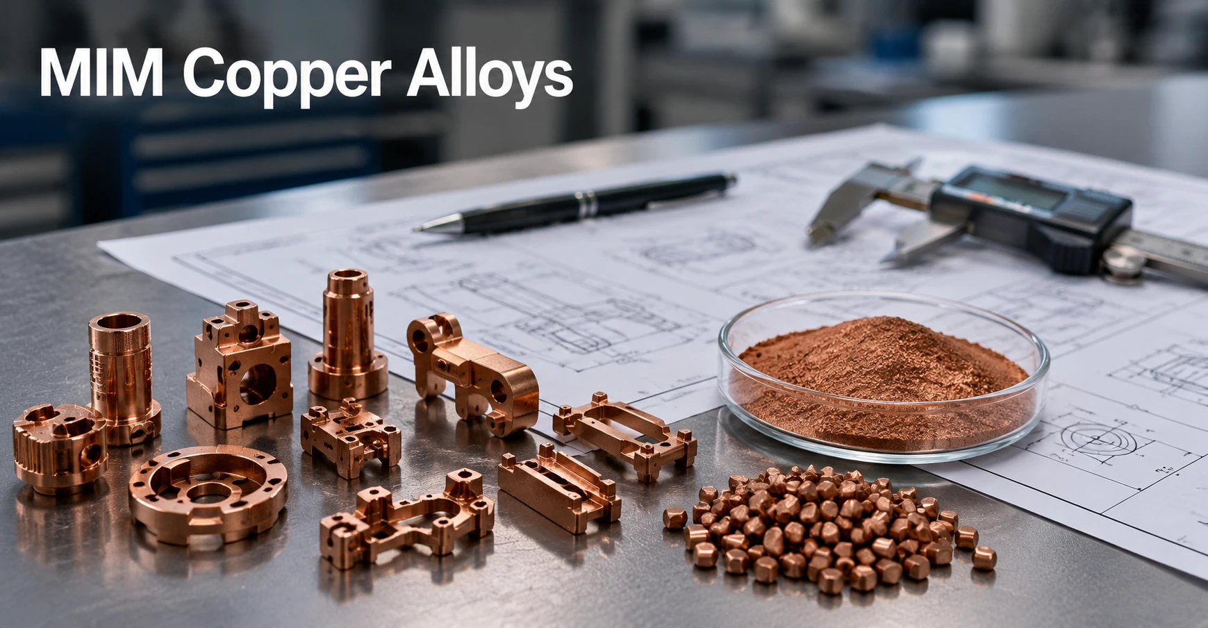
Selected copper and copper-alloy systems can be evaluated for metal injection molding when a project combines small three-dimensional geometry with electrical, thermal or copper-based functional requirements. Suitability must be confirmed through fine-powder availability, feedstock stability, molding behavior, debinding, sintering response, dimensional compensation and final inspection. A copper alloy name used for machining, stamping, casting or conventional powder metallurgy does not automatically define a viable MIM material.
XTMIM reviews drawing-based projects for finished custom copper or copper-alloy MIM components. This is not a copper powder, MIM feedstock, wrought brass stock, cast bronze, PM bearing or oil-impregnated bushing product catalog. Material availability and production feasibility are confirmed for each project before tooling.
Can Copper Alloys Be Used for Metal Injection Molding?
Yes, selected copper and copper alloy systems can be processed by MIM, but they require more careful review than common stainless steel MIM grades. Stainless steels such as 316L or 17-4 PH are widely used in MIM with mature feedstock systems and established production experience. Copper-based materials are more sensitive to powder oxygen content, impurity control, sintering atmosphere, residual carbon, porosity and final conductivity.
From a design review perspective, copper MIM is usually considered when the part has a three-dimensional shape that is not suitable for simple stamping, when CNC machining would remove too much material, or when a compact conductive or thermal component needs repeatable production. The value is not only the copper alloy itself. The value is the combination of material function and MIM geometry freedom.
A common mistake is to assume that any copper alloy used in machining, casting or PM can be moved directly into MIM. In practice, the nominal alloy name is only the starting point. The manufacturability depends on fine powder availability, binder compatibility, molding behavior, debinding control, sintering response and inspection requirements.
Where Copper Alloy MIM Makes Engineering Sense
Copper alloy MIM is most relevant when the part needs both material function and shape complexity. If the part is a flat terminal, stamping may be the better choice. If it is a simple round copper pin, bar stock machining may be more practical at low volumes. If it is a large bronze bushing, PM or casting is usually closer to the correct manufacturing route.
Copper MIM becomes more attractive when several of the following conditions are present:
| Project condition | Why MIM may be considered | What must be reviewed |
|---|---|---|
| Small three-dimensional conductive part | MIM can form compact geometry with features that are difficult to stamp. | Feedstock flow, gate position, sintering shrinkage and final conductivity. |
| Complex heat dissipation structure | MIM may form compact thermal geometry closer to net shape. | Density, porosity, thermal conductivity and surface condition. |
| Miniature connector or contact hardware | MIM can integrate small three-dimensional features into one part. | Contact surface, plating strategy, dimensional repeatability and burr control. |
| RF or sensor-related hardware | MIM may support compact shielding, mounting or conductive features. | Material stability, surface finish, assembly tolerance and electrical path. |
| Conductive mechanical part with internal geometry | MIM may reduce secondary machining when geometry is complex enough. | Debinding risk, sintering distortion, datum strategy and critical dimensions. |
In production, copper MIM is usually not selected only because copper is conductive. It is selected when conductive or thermal performance must be combined with a shape that benefits from injection molding and sintering-based near-net-shape production.
Copper Alloy Families for MIM Feasibility Review
The following material families are presented as engineering review candidates, not as standard stock feedstocks or guaranteed production offerings. Actual feasibility depends on a suitable fine-powder source, stable feedstock preparation, molding and debinding behavior, sintering response, final property targets and supplier-specific validation.

| Copper alloy family | Example naming | Review status | Engineering note |
|---|---|---|---|
| High-conductivity copper | HC Cu / high-purity Cu | Feasibility-review candidate; source confirmation required | Potentially relevant for conductive or thermal parts. Final performance depends on powder quality, sintered density, oxygen, impurities and residual porosity. |
| Oxygen-free copper | OFHC Cu | Feasibility-review candidate; source confirmation required | Relevant to low-oxygen and conductivity-oriented projects, but powder and feedstock availability must be confirmed before tooling. |
| Copper-aluminum alloy | Cu10Al reference chemistry | Project-specific candidate; availability unconfirmed | The reference chemistry may be evaluated when project requirements justify it. It is not presented as a standard stock MIM feedstock. |
| Copper-tin alloy system | Cu-Sn | Project-specific candidate; availability unconfirmed | Evaluate the copper-tin system against powder, feedstock and performance requirements. Do not equate it directly with standard bearing-bronze grades. |
| Copper-nickel alloy system | Cu-Ni | Project-specific candidate; availability unconfirmed | Potentially relevant where corrosion behavior or stable service performance matters, subject to project-level material and process validation. |
XTMIM does not represent Cu10Al, Cu-Sn, Cu-Ni or other non-standard copper-alloy systems as universally available feedstocks. A quotation should follow confirmation of the powder source, feedstock route, sample plan, final acceptance targets and drawing-based process feasibility.
For a requested chemistry outside established production materials, use the custom MIM materials review route rather than transferring a machining, casting or wrought-alloy designation directly into the MIM specification.
Copper MIM Material and Process Boundaries
A copper or bronze designation is not sufficient to establish MIM suitability. Copper MIM requires a complete route based on fine powder, binder or feedstock preparation, injection molding, controlled debinding, sintering, shrinkage compensation and final property verification. Conventional PM copper and bronze use compaction-based forming logic, while wrought brass, cast bronze and machined copper start from different material forms and process assumptions.

| Material or part request | Typical manufacturing context | Copper MIM review decision |
|---|---|---|
| HC Cu or OFHC Cu miniature conductive component | Conductive or thermal function combined with small complex geometry. | May enter MIM feasibility review after powder, feedstock, density and performance requirements are confirmed. |
| Cu10Al, Cu-Sn or Cu-Ni reference chemistry | Project-specific copper-alloy performance requirement. | Treat as a candidate chemistry only. Do not assume stock feedstock availability or routine production capability. |
| SAE 660 / C93200 or SAE 620 / C90300 | Bearing bronze, casting, PM, bushing or machining applications. | Use as a route-selection boundary. These designations are not presented as standard copper MIM feedstocks. |
| Oil-impregnated bronze bearing or porous bronze component | Conventional PM with controlled porosity and possible oil impregnation. | Normally outside the copper MIM target range because porosity is an intended PM feature. |
| H62, H63, C26000, C36000 or similar brass stock | Wrought strip, tube, bar, stamping or machining. | Requires separate Cu-Zn powder, feedstock, zinc-control and sintering feasibility review; stock-form availability does not prove MIM suitability. |
| Large, simple bronze sleeve, valve body or pump component | PM, casting or machining depending on size, geometry and quantity. | Usually better evaluated through those processes unless the design contains genuine small-complex MIM geometry. |
Copper MIM vs PM Copper, CNC, Stamping and Casting
Copper MIM is one manufacturing route among several. The right choice depends on geometry, quantity, material function, tolerance, secondary operations and cost structure.

| Manufacturing route | Better fit | Not ideal for | Key decision point |
|---|---|---|---|
| MIM copper alloys | Small, complex, three-dimensional conductive or thermal parts. | Large simple parts, flat strip parts and very low-volume prototypes. | Best when geometry complexity and material function both matter. |
| PM copper / bronze | Bushings, bearings, porous parts, oil-impregnated parts and relatively regular shapes. | Thin-wall undercuts, micro-features and complex 3D geometry. | Strong for cost-sensitive regular shapes, but not the same as MIM. |
| CNC machining | Low-volume parts, prototypes and local precision features. | High-volume complex parts with high material waste. | Good for validation, low-volume production or secondary machining. |
| Stamping | Flat terminals, contacts, spring features and shielding sheets. | Thick 3D structures or enclosed complex features. | Best for sheet-metal geometry. |
| Casting | Larger bronze or copper alloy components, pump and valve bodies. | Small precision MIM-like geometries. | Better for larger section parts and casting-friendly shapes. |
Regular PM bushings, oil-impregnated bearings, porous bronze components and wrought brass stock follow different design and production logic. They should be evaluated through their corresponding PM, casting, stamping, machining or wrought-material routes rather than being defaulted to MIM.
For the general manufacturing route, see the MIM process overview. For the material preparation stage, see MIM feedstock.
Key Process Risks in Copper Alloy MIM
Copper alloy MIM is not only a material selection question. It is a process control question. A material that looks suitable on a chemistry sheet can still fail at the project level if the feedstock cannot fill the geometry, the binder removal creates defects, the sintering response is unstable, or the final part does not meet conductivity and dimensional requirements.

Powder Oxygen and Impurity Control
Copper’s electrical and thermal performance can be affected by oxygen, impurities and porosity. For high-conductivity copper or OFHC copper projects, engineers should not rely only on nominal alloy naming. They should confirm powder quality, supplier process capability and final inspection requirements.
Feedstock Flow and Molding Stability
The fine copper powder must be compounded with binder into a stable feedstock. During molding, the feedstock must fill small features without short shots, flow lines, severe separation or gate-related defects. Thin walls, ribs, blind holes and miniature conductive features should be checked before tooling.
Debinding Residue and Carbon Control
Debinding must remove the binder without leaving residue that harms sintering or final properties. For copper and copper alloys, residual carbon or contamination can affect density, surface condition and performance. Debinding problems may also lead to cracking, blistering or internal defects that become visible only after sintering.
Related page: MIM debinding
Sintering Atmosphere and Densification
Sintering must develop density while controlling shrinkage and distortion. Copper alloy parts may require careful atmosphere selection and thermal profile control. A part that looks acceptable after molding can still fail after sintering if densification is uneven or the geometry is not well supported.
Related page: MIM sintering
Porosity and Conductivity Loss
For conductive and thermal applications, porosity is not only a mechanical issue. It can reduce conductivity, affect heat flow and create variability between lots. If the application depends on conductivity, the requirement should be stated in the RFQ instead of assumed from the copper alloy name.
Dimensional Shrinkage and Distortion
MIM parts shrink during sintering. Copper alloy materials require part-specific review of wall thickness, section transitions, flatness, hole position, gate location and support strategy. This is especially important for miniature connectors, thin ribs and conductive parts that must assemble with plastic housings, springs, pins or PCB-related components.
Related page: MIM tolerances
Typical Applications for MIM Copper Alloy Parts
Copper alloy MIM should be discussed through the lens of part geometry and functional requirements. Suitable application directions may include:
| Application direction | Why copper MIM may be reviewed | Key engineering concern |
|---|---|---|
| Electrical contact hardware | Conductive material plus compact geometry. | Contact surface, plating, dimensional repeatability and wear condition. |
| Miniature connectors | Small features and integrated geometry. | Thin walls, pin alignment, gate mark location and assembly fit. |
| RF or shielding components | Compact conductive features. | Surface condition, assembly fit and material stability. |
| Sensor hardware | Small structural-conductive components. | Dimensional control and interface features. |
| Heat dissipation components | Copper thermal function with shaped geometry. | Density, porosity, thermal path and surface area. |
| Conductive mechanical parts | Combined mechanical and electrical role. | Strength, conductivity, wear and secondary operations. |
Large pump bodies, valve bodies, regular bronze sleeves and oil-impregnated bearings normally fit casting, machining or conventional PM more closely. Copper MIM is most relevant where small complex geometry and copper-based function must be combined in a finished component.
Design and RFQ Review Points Before Tooling
Copper alloy MIM projects should be reviewed before tooling. A material name alone is not enough for quotation, process planning or quality control. A useful RFQ package should connect the geometry, material target, functional requirement, tolerance strategy and production volume. For geometry-focused review, see DFM review for MIM parts.

Drawing and Geometry Checklist
- 2D drawing with critical dimensions and tolerances.
- 3D CAD file for geometry, wall thickness and feature review.
- Critical assembly interfaces and datum expectations.
- Thin walls, ribs, holes, slots, undercuts and sharp transitions.
- Expected gate mark restrictions.
- Flatness, concentricity, hole position or datum requirements.
- Any secondary machining or finishing surfaces.
Material and Performance Checklist
- Target copper alloy family or reference material.
- Electrical conductivity or thermal performance requirement, if applicable.
- Corrosion or operating environment.
- Required surface finish, contact surface or plating requirement.
- Mechanical load, wear or contact condition.
- Application temperature range.
- Whether the part must match wrought copper properties or only meet functional project targets.
Production and Purchasing Checklist
- Estimated annual volume.
- Prototype or sample expectations.
- Target production timeline.
- Inspection requirements.
- Packaging or handling requirements for delicate conductive surfaces.
- Existing process comparison, such as CNC, stamping, PM or casting.
Inspection and Acceptance Checks for Copper MIM Parts
Inspection planning should be defined before production. Copper alloy MIM parts may need both dimensional and functional checks. If conductivity, thermal performance or plating quality is part of the product function, those requirements should be stated before tooling instead of being assumed from the alloy family name.
| Inspection area | Why it matters |
|---|---|
| Dimensional inspection | Confirms shrinkage compensation, datum strategy and assembly fit. |
| Density review | Helps evaluate sintering quality and possible porosity. |
| Surface inspection | Important for contact areas, plating, appearance and assembly. |
| Conductivity or thermal validation | Required if electrical or heat-transfer performance is part of the function. |
| Microstructure review | Useful when density, porosity or abnormal defects must be investigated. |
| Oxygen / impurity confirmation | Relevant for high-conductivity or oxygen-sensitive copper projects. |
| Secondary operation control | Needed when machining, plating, polishing or heat treatment affects final use. |
The current edition of MPIF Standard 35-MIM may be consulted for MIM terminology and for material specifications that are actually included in that standard. It does not establish that every copper-alloy candidate discussed here is standardized, commercially available as feedstock or within a supplier’s routine production capability. Powder source, feedstock route, drawing feasibility, sample validation and project-specific acceptance criteria remain necessary.
When Copper Alloy MIM May Not Be the Best Choice
Copper MIM is not the right answer for every copper part. It may not be the best route when:
- The part is a flat stamped terminal or spring contact.
- The part is a simple pin, rod, ring or spacer that can be machined economically.
- The part is a large bronze bushing, sleeve or bearing.
- The required material is a PM oil-impregnated bronze.
- The part needs a porous bronze structure.
- The required conductivity must closely match wrought copper and cannot tolerate MIM-related variability.
- The selected alloy powder or feedstock is not commercially practical.
- The annual volume is too low to justify tooling.
- Critical tolerances require extensive post-machining anyway.
The correct question is not whether copper is a valuable material. The correct question is whether the geometry, performance target, quantity and manufacturing route fit MIM.
Representative Engineering Scenario: Conductive Connector Housing
Initial issue: A compact conductive connector housing was specified as a generic brass alloy because the prototype had been machined from brass bar stock.
Why the specification needed review: The prototype material had been carried into the production concept without confirming whether the same chemistry was available and stable in a powder-and-feedstock MIM route.
Engineering decision: The part contained small ribs, internal features and assembly interfaces that could benefit from MIM, but the requested brass grade had not been confirmed for powder availability, zinc control, feedstock stability or sintering response.
Review approach: The project was evaluated through candidate copper material families, conductivity targets, plating requirements, wall thickness, dimensional interfaces and annual volume rather than assuming a direct brass-grade conversion.
RFQ lesson: A CNC prototype material should not be transferred automatically into a MIM production specification. Powder and feedstock availability, sintering risk, final conductivity and inspection criteria must be reviewed first.
Representative Engineering Scenario: Bronze Bushing Process Selection
Initial issue: A regular bronze sleeve bushing was submitted for a MIM quotation with SAE 660 referenced as the material.
Why the request needed review: The term “powder metal” had been applied broadly without distinguishing injection-molded feedstock from conventional powder compaction, casting or machining routes.
Engineering decision: The cylindrical geometry and primary friction-and-wear requirement aligned more closely with bearing bronze, PM, casting or machining than with MIM geometry freedom.
Review approach: The material requirement and manufacturing route were separated. MIM was not treated as the default process, and the component was evaluated through routes better suited to regular bearing geometry.
RFQ lesson: A regular bushing, oil-impregnated bearing, porous sleeve or large cast-bronze component should first be evaluated through conventional PM, casting or machining unless the design contains genuine small-complex MIM features.
Copper Alloy MIM Project Review by XTMIM
Contact XTMIM when your copper-based part requires small complex geometry, conductive or thermal function, tight assembly interfaces, or a production route comparison between MIM, PM, CNC, stamping and casting.
For copper alloy MIM projects, please provide 2D drawings, 3D CAD files, target material or reference alloy, electrical or thermal performance requirements, surface finish or plating needs, tolerance expectations, estimated annual volume and application background. XTMIM reviews whether the copper alloy family is realistic for MIM, whether the geometry is suitable for molding and sintering, whether critical dimensions require secondary machining, and whether another manufacturing route may reduce project risk before tooling begins.
FAQ: Copper Alloys for MIM
Can copper alloys be used in metal injection molding?
Yes. Selected copper and copper-alloy systems can enter MIM feasibility review when the part combines small complex geometry with electrical, thermal or other copper-based functional requirements. Suitability still depends on powder availability, feedstock stability, molding, debinding, sintering response, density, final properties and part geometry.
Which copper alloys are most relevant for MIM review?
HC Cu and OFHC Cu may be reviewed for conductivity-oriented projects, while Cu10Al, Cu-Sn and Cu-Ni may be considered as project-specific reference chemistries. These are engineering review candidates, not universal stock feedstocks or guaranteed production options.
Is OFHC copper suitable for MIM parts?
OFHC copper may be considered when low oxygen content and conductivity potential are important. The project must still confirm powder quality, feedstock availability, sintered density, impurity control and whether the finished component can meet its electrical or thermal acceptance targets.
Can brass be processed by MIM?
A Cu-Zn brass system may be evaluated case by case, but availability as brass bar, strip, tube or stamping stock does not prove MIM suitability. Zinc behavior, powder source, feedstock stability, debinding, sintering atmosphere, dimensional control and final properties must be confirmed before tooling.
Are SAE 660 / C93200 and SAE 620 / C90300 standard copper MIM materials?
No such assumption should be made. These designations are strongly associated with bearing bronze, casting, PM, bushings and wear applications. They should be treated as route-selection references unless a project-specific powder, feedstock, debinding, sintering and property-validation path has been confirmed.
What is the difference between MIM copper and PM bronze?
MIM uses fine metal powder mixed with binder to create injection-molding feedstock, followed by debinding and sintering. Conventional PM bronze normally uses powder compaction and sintering and is commonly associated with bushings, bearings, porous parts or oil-impregnated components. The processes use different geometry rules, porosity assumptions and cost structures.
What information is needed for a copper alloy MIM RFQ?
Provide 2D drawings, 3D CAD files, the target material or reference chemistry, electrical or thermal requirements, surface finish or plating needs, critical tolerances, estimated annual volume and application conditions. This allows review of material sourcing, feedstock feasibility, tooling risk, sintering behavior, inspection needs and whether MIM is the correct route.
Engineering Review Note
Reviewed by: XTMIM Engineering Team
This article was reviewed from the perspective of MIM material suitability, copper alloy selection, feedstock feasibility, debinding and sintering risk, dimensional control, inspection requirements and production feasibility. The purpose is to help engineers and sourcing teams distinguish MIM copper alloy candidates from PM bronze, cast bronze and wrought brass materials before requesting tooling or production quotation.
Standards and Technical References
MIMA / MPIF Standard 35-MIM: consult the current edition for MIM terminology and for material specifications explicitly included in that standard. The standard should not be interpreted as evidence that every copper-alloy family discussed on this page is standardized, commercially available as feedstock or qualified within XTMIM’s routine production capability. External references: MIMA Standard 35-MIM page and MPIF standards resources.
Copper Development Association resources: these references provide conventional copper-alloy composition, property and application context. They are useful for understanding why C93200 / SAE 660 and C90300 / SAE 620 are commonly associated with bearing bronze or casting, but they do not establish a viable MIM powder, feedstock or production route. External references: bronze bearing materials, C93200 alloy data and C90300 alloy data.
Project qualification: supplier-specific powder and feedstock confirmation, drawing-based DFM review, sample validation and agreed acceptance criteria are required before any candidate copper-alloy chemistry is treated as a production material.