
Binder Removal, Brown-Part Stability, and Preparation for Sintering
In metal injection molding, debinding is the controlled removal of binder from a molded green part before sintering. The objective is to create a porous but handleable brown part with open escape paths for the remaining binder and decomposition gases.
This page is the parent guide to the MIM debinding process. It explains how binder chemistry, wall thickness, escape distance, part support, and process verification affect cracking, blistering, distortion, residual carbon, and final sintering stability. Detailed route-specific controls are covered separately in the solvent debinding process and thermal debinding process guides.
For engineering review, the key question is not only whether a part can be injection molded. It is whether binder can leave the geometry at a controlled rate without damaging the weak powder structure before MIM sintering.
Quick Answer: What Does Debinding Do in the MIM Process?
Debinding removes the primary binder from a molded MIM green part and forms an interconnected pore network while a secondary backbone helps the part retain its shape. The resulting brown part is fragile but prepared for the remaining binder to escape during thermal treatment and for the metal powder to densify during sintering.
| Engineering Question | Debinding Requirement |
|---|---|
| What must be removed? | The removable binder phase inside the full part volume, not only contamination on the surface. |
| What must remain stable? | The powder structure, critical features, and any backbone binder needed for handling and loading. |
| What must be created? | Open pore channels that allow the remaining binder and gases to escape without excessive internal pressure. |
| What must be prevented? | Cracking, blistering, swelling, slumping, handling damage, residual binder, and uneven shrinkage after sintering. |
Process boundary: This parent page explains the complete debinding decision path. Route-specific operating details belong on the solvent and thermal debinding child pages rather than being duplicated here.
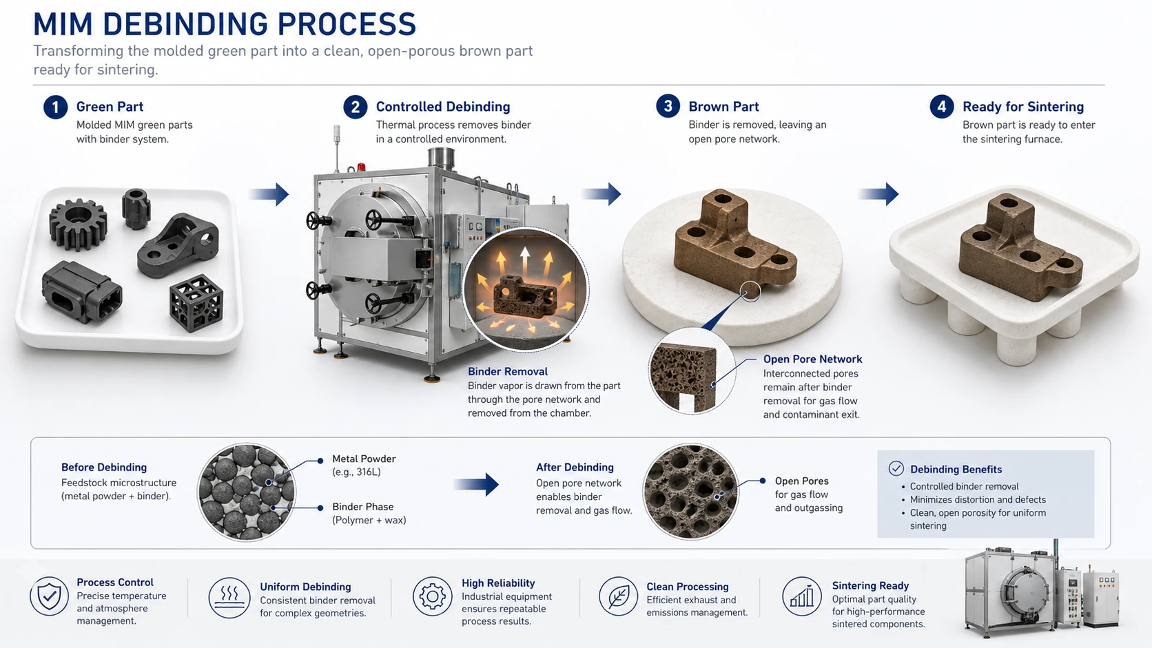
Illustration note: This is a representative engineering diagram, not a photograph of a customer part or a production test result.
Engineering takeaway: The brown part must retain enough structural support while gaining open pore channels for the remaining binder and gases to escape during later heating.
What Is Debinding in Metal Injection Molding?
Metal injection molding feedstock combines fine metal powder with a multi-component binder so the material can flow during injection molding. After molding, the binder is temporary: the removable phase must leave the part before metal particles can bond and densify during sintering.
The molded component is called a green part. After the primary binder phase is removed, it becomes a porous brown part. The brown part keeps the general geometry but has limited strength, so handling, tray loading, setter contact, and transfer to the furnace must be controlled.
The MIMA process overview describes the same staged principle: most of the first-stage binder is removed while a secondary backbone temporarily maintains part geometry before final thermal removal and densification.
What Changes from Green Part to Brown Part?
Binder removal progresses through the part volume rather than cleaning only the surface. As the removable phase leaves, interconnected pores form from the surface toward the interior. These channels reduce the risk that remaining binder or decomposition gases will become trapped during later heating.
The process must preserve a usable balance: enough binder must be removed to create escape paths, but enough temporary support must remain for weak features to survive handling and furnace loading.
Why Must Binder Removal Be Controlled?
If removal is too fast, the outer region may lose binder before the core has a safe escape path, creating stress or internal gas pressure. If the binder softens before a stable pore network forms, unsupported areas may slump. If removal is incomplete, residue can affect carbon control, atmosphere response, densification, and final properties.
Thick sections, blind holes, deep slots, enclosed features, abrupt wall transitions, and large unsupported surfaces therefore require more review than thin, open, and uniform geometries.

Illustration note: Representative engineering illustration for process explanation; it is not presented as a customer part, production record, or measured defect result.
Core conclusion: The key engineering purpose of debinding is to create controlled internal pore channels, not simply to remove binder quickly.
Binder removal usually progresses from the outside surface toward the inner core. If the outer region debinds much faster than the center, the part may develop internal pressure or stress imbalance. This is why thick sections, blind holes, and long binder removal paths require slower and more carefully controlled debinding conditions.
Why the MIM Debinding Process Is Critical Before Sintering
Debinding is critical because sintering depends on a stable brown part structure. If the binder has not been removed correctly, the sintering furnace will not fix the root cause. In many cases, sintering only makes the problem easier to see.
A part can look acceptable after injection molding but still fail during debinding or early sintering if the internal binder removal path is not controlled. Experienced MIM manufacturers review molding, debinding, and sintering as one connected process chain, not as three isolated steps.
Debinding Creates Escape Paths for Remaining Binder
The purpose of debinding is not always to remove all binder at once. In many MIM systems, the primary binder is removed first, while some backbone binder remains to support the brown part before final thermal removal.
The controlled removal of the primary binder creates open pore channels. These channels allow remaining binder and decomposition gases to escape during heating. Without these escape paths, gas pressure can build inside the part and cause cracking, blistering, or internal defects.
Debinding Protects Shape Before High-Temperature Shrinkage
Sintering causes the part to shrink and densify. In MIM, shrinkage is expected and designed into the tooling through an oversize factor. However, shrinkage must be stable and predictable.
If debinding creates uneven pore structure, internal cracks, partial collapse, or local binder residue, the sintering stage may produce uneven shrinkage. The final part may show distortion, dimensional drift, density variation, or surface defects.
Debinding Affects Carbon, Porosity, and Mechanical Properties
Debinding also affects final material quality. Incomplete binder removal can leave carbon residue or contamination. Depending on the material system, sintering atmosphere, and thermal profile, this may influence carbon content, corrosion behavior, magnetic performance, hardness, ductility, or strength.
For stainless steels, low alloy steels, controlled expansion alloys, and magnetic alloys, debinding and sintering atmosphere should be reviewed together. A profile that works for one feedstock system should not be copied blindly to another.
Main Debinding Methods Used in MIM
The complete MIM debinding process may use catalytic, solvent, thermal, aqueous, or combined removal stages. Method selection begins with binder chemistry and feedstock architecture, then considers wall thickness, extraction distance, feature support, furnace route, material sensitivity, and production scale.
A metal grade alone does not define the cycle. Asking for one public “316L debinding temperature” or “17-4PH debinding time” ignores differences in binder systems, powder loading, geometry, equipment, and atmosphere. The engineering question is: Which removal mechanism is compatible with this feedstock, and can the part release binder without losing shape?
This parent guide compares the available routes and their selection logic. Use the dedicated solvent debinding process and thermal debinding process pages for method-specific risk and control details. The EPMA overview of metal injection moulding provides broader process context.

Illustration note: Representative engineering illustration for process explanation; it is not presented as a customer part, production record, or measured defect result.
Core conclusion: There is no universal debinding method for all MIM parts. The correct route depends on binder chemistry, feedstock system, part thickness, and geometry.
Catalytic debinding is often used with POM-based binder systems. Solvent debinding extracts a soluble binder phase to form pore channels. Thermal debinding removes binder through controlled heating. Each method has its own equipment, control points, and defect risks.
Catalytic Debinding
Catalytic debinding is commonly associated with POM-based binder systems and Catamold-type feedstocks. In this process, the binder is decomposed in a controlled acid vapor atmosphere, usually at a relatively low temperature compared with thermal debinding. The reaction proceeds from the surface inward, creating pore channels while helping the part maintain shape.
The BASF Catamold catalytic debinding reference is a useful technical source for understanding POM-based feedstock and acid-catalyzed binder removal. In production, this route requires correct equipment, acid vapor control, exhaust treatment, and feedstock compatibility.
Solvent Debinding
Solvent debinding removes a soluble binder component by immersing the green part in a compatible solvent. As the soluble phase is extracted, pore channels form inside the part. After solvent debinding, the remaining binder is usually removed during thermal treatment or sintering.
Key risks include swelling, cracking, drying defects, solvent residue, and uneven extraction in thicker sections.
Thermal Debinding
Thermal debinding removes binder by heating the part under a controlled temperature profile and atmosphere. The binder decomposes or evaporates gradually as the part is heated.
If the temperature rises too quickly, binder can decompose before enough escape channels exist. This may cause internal pressure, blistering, cracking, or local collapse.
Aqueous or Water-Based Debinding
Aqueous debinding uses water to remove a water-soluble binder component. It is suitable only for specific binder systems. After water-based debinding, the part still normally needs thermal treatment to remove remaining binder and prepare for sintering.
It should not be treated as a universal solution. Drying cracks, incomplete removal, and geometry-related removal differences still need to be controlled.
| Debinding Method | Main Mechanism | Suitable For | Key Risks |
|---|---|---|---|
| Catalytic debinding | Acid vapor decomposes specific binder systems | POM-based feedstocks, high-volume MIM | Acid control, exhaust safety, feedstock compatibility |
| Solvent debinding | Solvent extracts soluble binder phase | Selected binder systems, delicate parts | Swelling, cracking, drying defects, solvent residue |
| Thermal debinding | Heat decomposes or evaporates binder | Broad furnace-based systems | Blistering, long cycles, distortion, internal pressure |
| Aqueous debinding | Water removes water-soluble binder | Water-soluble binder systems | Drying cracks, incomplete removal, geometry limits |
How Binder System and Feedstock Affect Debinding
Feedstock is one of the strongest factors affecting debinding. A MIM feedstock is not simply “metal powder.” It is a mixture of metal powder and binder, engineered to flow during injection molding and then release binder during debinding and sintering.
This is why two materials with the same metal name may still require different debinding conditions if they use different binder systems.
Binder Chemistry Comes Before Furnace Settings
The MIM binder system determines the debinding route. A POM-based catalytic system, a wax-polymer solvent system, and a thermally debound binder system cannot be processed in the same way.
From a project review perspective, it is not enough to select a metal grade and then ask for a fixed debinding cycle. The manufacturer must understand binder type, powder loading, powder-binder distribution, green part density, wall thickness, expected shrinkage, and atmosphere requirements during sintering.
Powder Loading and Binder Distribution
Powder loading affects both molding behavior and debinding behavior. If the powder-binder mixture is not uniform, some areas of the green part may have different binder content or green density. During debinding, these local differences may cause uneven pore formation.
This can lead to local cracking, uneven shrinkage after sintering, density variation, weak edges, and unstable dimensions between batches.
Why the Same Material Name May Need Different Debinding Parameters
A common buyer-side mistake is assuming that every 316L, 17-4PH, 4605, 4140, or Fe-Ni alloy uses the same debinding profile. In reality, debinding depends on the feedstock supplier, binder system, part geometry, and furnace route.
Debinding should therefore be treated as a project-specific process review item rather than a fixed parameter table. Material selection, green part molding quality, debinding route, and sintering profile should be reviewed together.
How Part Geometry Affects Debinding Stability
Part geometry strongly affects debinding. A part that is easy to mold may still be difficult to debind. This is especially true for MIM because the parts are often small, complex, and selected specifically because machining or casting would be inefficient.
From a DFM perspective, debinding risk should be reviewed before tooling. Wall thickness, blind features, support surfaces, and binder escape paths all influence whether the brown part can reach sintering without cracks, blisters, or local collapse.

Illustration note: Representative engineering illustration for process explanation; it is not presented as a customer part, production record, or measured defect result.
Core conclusion: A part that can be injection molded may still be difficult to debind if its geometry restricts binder removal or weakens brown part support.
Thick sections increase binder removal distance. Blind holes and deep slots restrict gas escape. Thin walls and flat unsupported areas may become fragile after binder removal. These geometry risks should be reviewed before MIM tooling because they affect debinding, sintering shrinkage, and final dimensional stability.
Wall Thickness and Binder Removal Distance
Wall thickness is one of the most important debinding factors. The thicker the section, the longer the binder removal path. If the outer region debinds faster than the inner core, internal stress and gas pressure can develop.
Thick sections may require slower debinding cycles, longer holding time, modified geometry, improved support, adjusted gate and molding strategy, or additional sintering risk review.
Blind Holes, Deep Slots, and Enclosed Cavities
Blind holes and deep slots can restrict binder escape. The risk is higher when these features are combined with thick walls or sharp transitions.
During DFM review, engineers should check whether the geometry allows binder removal and gas release without excessive pressure buildup.
Thin Walls, Flat Sections, and Unsupported Areas
Thin walls and large flat surfaces create a different type of risk. These areas may debind more quickly, but the brown part may be too weak to resist deformation.
Flat parts, thin ribs, long arms, and unsupported overhanging sections may require carefully designed setter support. If the support is poor, the part may sag, twist, or distort before or during sintering.
Common Debinding Defects and Root Causes
Debinding defects may appear during the debinding stage, after brown part handling, or during early sintering. In many cases, the root cause begins earlier in the process chain.
A part may look acceptable as a green part but fail during debinding because of internal density variation, trapped air, binder segregation, wall thickness imbalance, or an aggressive debinding profile.

Illustration note: Representative engineering illustration for process explanation; it is not presented as a customer part, production record, or measured defect result.
Core conclusion: Most debinding defects are not random. They usually come from a mismatch between binder system, part geometry, removal rate, support method, and thermal profile.
Cracking can result from fast binder removal or stress imbalance. Blistering often indicates trapped gas or incomplete pore formation. Warpage and slumping are related to weak brown part strength and poor support. Residual binder may lead to carbon or sintering-related property problems.
Cracking
Cracking is one of the most common debinding-related defects. It can occur when binder removal is too fast, when the internal binder cannot escape, or when solvent swelling creates internal stress.
Possible causes include rapid binder removal, excessive heating rate, solvent swelling, uneven green density, poor gate location, abrupt wall thickness changes, weak green part handling, and poor support during debinding.
Blistering
Blistering occurs when internal gas pressure forms beneath the part surface. This usually means binder or decomposition gas cannot escape quickly enough.
Blisters are not cosmetic only. They can indicate internal binder removal failure and may affect final density and strength.
Warpage and Slumping
Warpage and slumping are usually related to weak brown part strength, poor support, or thermal softening during binder removal.
In MIM, support design is not an afterthought. Brown parts are porous and fragile. The way they are loaded can influence the final part geometry.
Residual Binder and Carbon Issues
If binder is not removed completely or predictably, residual carbon or contamination may affect sintering and final properties.
Depending on the material system, carbon control can influence hardness, strength, ductility, corrosion resistance, magnetic properties, dimensional stability, and surface condition.
Contamination and Surface Defects
Debinding may also contribute to surface stains, discoloration, contamination, or reaction marks if the atmosphere, furnace cleanliness, binder residue, solvent residue, or setter material is not controlled.
| Defect | Likely Cause | Where It Appears | Prevention |
|---|---|---|---|
| Cracking | Fast binder removal, swelling, uneven green density | Brown part or sintered part | Slower profile, suitable solvent, better molding control |
| Blistering | Trapped gas or incomplete pore channels | Debinding or early sintering | Controlled heating and proper pore formation |
| Warpage | Weak brown part or poor support | Brown part or sintered part | Setter design, loading control, geometry review |
| Residual carbon | Incomplete binder removal | Final material property | Atmosphere control and thermal profile validation |
| Surface stains | Contamination or binder residue | Brown or sintered surface | Clean furnace, compatible support, stable atmosphere |
Debinding Process Control Points in Production
A stable debinding process depends on more than equipment. The process must be controlled through material understanding, process profile, part loading, verification, and connection to sintering.
How XTMIM Controls Debinding Before Sintering
XTMIM handles debinding in-house and treats it as a controlled transition between injection molding and sintering. The review focus is not a universal public cycle. It is whether the selected binder-removal route, loading method, brown-part condition, and handoff to sintering are suitable for the specific feedstock and part geometry.
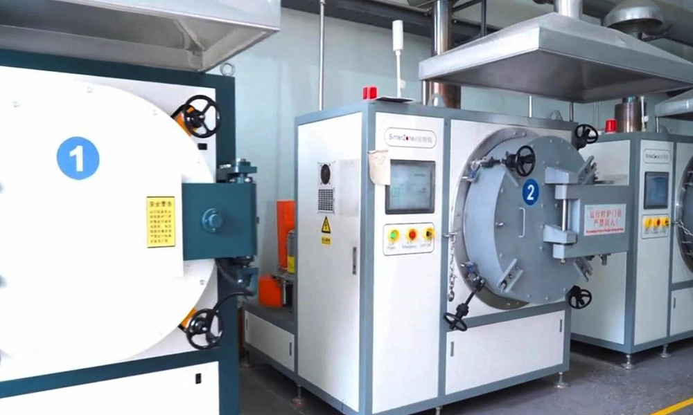
Project-specific control: Exact temperature, time, atmosphere, solvent, catalytic conditions, and acceptance limits depend on the feedstock, geometry, material, and final performance requirements. They should be confirmed through project review and trial validation rather than copied from a generic public parameter table.

Illustration note: Representative engineering illustration for process explanation; it is not presented as a customer part, production record, or measured defect result.
Core conclusion: Debinding quality depends on a controlled production workflow, not only on having a debinding furnace.
A reliable MIM debinding process should include green part inspection, proper tray loading, controlled debinding conditions, weight loss or debinding rate verification, brown part inspection, and stable transfer to sintering. This workflow helps reduce cracks, deformation, residual binder, and final dimensional instability.
Temperature Profile and Holding Time
The temperature profile must match the binder system and part structure. A slow profile is not automatically better, and a fast profile is not automatically wrong. The profile should allow binder removal without excessive internal pressure, deformation, or residue.
Atmosphere, Acid Vapor, Solvent, or Vacuum Control
Different debinding routes require different controls. For catalytic debinding, acid vapor concentration, gas flow, temperature, and exhaust treatment are important. For solvent debinding, solvent type, extraction temperature, time, drying, and swelling control are critical. For thermal debinding, heating rate, atmosphere, flow, pressure, and furnace cleanliness matter.
Debinding Rate or Weight Loss Verification
Debinding should be verified before the part moves into sintering. Depending on the process route and internal quality plan, verification may include weight loss measurement, debinding rate check, visual inspection, brown part crack inspection, sample section review, sintered density verification, carbon or chemistry check when required, and dimensional comparison after sintering.
Brown Part Handling and Setter Design
The brown part is weaker than the molded green part in many practical situations. It is porous and can be damaged by rough handling, point contact, stacking pressure, or unsupported loading.
Good brown part handling includes stable tray loading, suitable ceramic setter support, spacing between parts, support for thin or flat areas, and controlled transfer into sintering.
Process Control Points for Debinding Projects
| Process Stage | What Must Be Controlled | Common Risk | Why It Matters to Final Parts | Typical Verification Method |
|---|---|---|---|---|
| Feedstock selection | Binder system, powder loading, material grade | Wrong debinding route or unstable binder removal | Affects pore formation, carbon control, and sintering stability | Feedstock data review, material confirmation, trial processing |
| Green part molding | Green density, gate quality, flow balance, internal stress | Density variation, weld lines, gate damage, hidden cracks | Uneven green parts often debind unevenly | Visual inspection, weight check, green part handling review |
| Debinding profile | Temperature, time, atmosphere, solvent or acid vapor condition | Cracking, blistering, swelling, incomplete binder removal | Determines whether the brown part can enter sintering safely | Weight loss check, debinding rate record, brown part inspection |
| Brown part handling | Tray loading, setter contact, part spacing, transfer method | Corner chipping, sagging, tray dents, handling cracks | Damage at this stage may become final distortion or scrap | Loading record, visual inspection, support review |
| Sintering transition | Remaining binder escape, atmosphere, support, shrinkage direction | Residual carbon, warpage, density variation, sintering distortion | Debinding quality directly affects final dimensional control | Sintered density, dimension check, surface inspection, hardness check when required |
How Debinding Connects Injection Molding and Sintering
Debinding is the bridge between injection molding and sintering. Problems from injection molding often appear during debinding, and problems from debinding often become final defects after sintering.
Green Part Quality Determines Debinding Risk
If the green part has uneven density, trapped air, internal stress, poor gate balance, weld lines, or weak trimming damage, debinding risk increases.
For example, a green part with local density variation may debind unevenly. A thin corner damaged during degating may crack during debinding. A thick section with poor flow packing may trap binder and gas during thermal treatment.
Debinding Quality Determines Sintering Stability
If debinding is incomplete or uneven, sintering becomes less predictable. The final part may show distortion, unstable shrinkage, cracks, low density, surface defects, carbon-related property changes, or poor mechanical consistency.
A Good Final Part Starts Before the Furnace
Many MIM defects are not caused by one isolated step. They result from a chain reaction:
Representative Engineering Scenario: Debinding Risk in a Thick-Walled MIM Part
Scenario disclosure: The following example combines common debinding risks seen in thick-to-thin MIM geometries. It is provided for engineering explanation and does not identify a specific customer project, production batch, or measured test result.
Consider a small stainless steel MIM component with a compact body, several thin features, and one thick mounting boss. The geometry may mold successfully while still developing cracks during debinding that become more visible after sintering.
Geometry and Process Situation
The part was designed for a compact assembly and required both a thick load-bearing boss and thin surrounding functional features. The first drawing looked suitable for MIM from a molding perspective, but the geometry created an uneven binder removal distance during debinding.
Likely Failure Pattern
Fine cracks appeared near the transition between the thick boss and thinner ribs. Some parts also showed slight distortion after sintering. The issue was not caused by one single furnace setting. It came from the interaction between wall thickness, green density, binder escape path, and brown part support.
Engineering Cause
The thick mounting boss created a long binder removal path. During debinding, the outer surface began forming pore channels, but the inner core released binder more slowly. If the debinding profile was too aggressive, internal pressure developed before the binder could escape safely. At the same time, the thinner features around the boss became weak earlier than the thick region, creating a stress imbalance.
Process Adjustment
- Reduced excessive wall thickness where the functional design allowed it.
- Added smoother transitions between thick and thin sections.
- Reviewed gate position and green density risk near the boss.
- Adjusted the debinding profile for the thicker section.
- Improved ceramic setter contact and brown part support.
- Used weight loss and brown part inspection before moving into sintering trials.
Expected Engineering Effect and Review Lesson
These adjustments would be expected to reduce trial risk and improve sintering stability, but the result must be confirmed through project-specific tooling trials, brown-part inspection, debinding verification, and final dimensional data. The main lesson is that furnace settings alone cannot fully compensate for a geometry that traps binder or lacks adequate support.
How Buyers Should Evaluate a MIM Supplier’s Debinding Capability
For purchasing teams and product engineers, debinding is not always easy to inspect directly. However, it is possible to evaluate whether a supplier understands the process.
A supplier that only says “we can do MIM” may not be enough for complex parts. For high-risk geometries, you should ask how the supplier controls binder removal, brown part handling, and the transition into sintering.
Ask Which Debinding Method Matches Your Feedstock
The supplier should be able to explain whether the project uses catalytic, solvent, thermal, aqueous, or combined debinding. The answer should be related to feedstock and binder chemistry, not just metal grade name.
Check Brown Part Handling and Setter Support
Ask how brown parts are loaded, supported, and transferred. Thin walls, flat sections, fragile ribs, and asymmetrical parts may need dedicated support strategies. Poor brown part handling can cause cracks and deformation even if the debinding furnace profile is correct.
Review How Debinding Completion Is Verified
A reliable supplier should have a method to verify that debinding is complete enough for sintering. This may include weight loss, debinding rate, visual inspection, sample checks, or sintered part validation.
Confirm Debinding and Sintering Are Reviewed Together
Debinding should not be separated from sintering. The debound brown part must be ready for the sintering atmosphere, temperature profile, support method, and shrinkage behavior.
| Buyer Question | Why It Matters |
|---|---|
| Which debinding route will be used for this feedstock? | Prevents the wrong binder removal strategy. |
| Does the part have thick sections or restricted binder escape paths? | Reduces cracking and blistering risk. |
| How will brown parts be supported? | Reduces warpage, slumping, and handling damage. |
| How is debinding completion verified? | Reduces residual binder and carbon-related problems. |
| Is debinding reviewed together with sintering shrinkage? | Improves final dimensional stability. |
| Does the supplier review debinding risk before tooling? | Avoids expensive redesign after mold completion. |
Send Your Drawing for Debinding and Sintering Risk Review
If your MIM part has thick sections, thin walls, blind holes, deep slots, flat areas, or tight dimensional requirements, debinding risk should be reviewed before tooling.
XTMIM can review your drawing from the full process chain: feedstock, injection molding, green part handling, debinding, sintering, and final inspection.
Send us your 2D drawing, 3D model, material requirement, estimated annual volume, and key functional dimensions. Our engineering team can help evaluate whether the part geometry, binder removal path, brown part support, and sintering plan are suitable for MIM production.
Submit Drawing for MIM ReviewMIM Debinding FAQs
What is debinding in MIM?
Debinding is the controlled removal of binder from a molded MIM green part before sintering. It creates a porous brown part with escape paths for the remaining binder and decomposition gases.
What is the difference between a green part and a brown part?
A green part is the molded component containing metal powder and binder. A brown part is the porous, fragile component after most of the removable binder phase has been extracted and before final sintering.
Which debinding method is best for MIM?
There is no universal best method. Catalytic, solvent, thermal, aqueous, or combined debinding must be matched to binder chemistry, feedstock type, geometry, wall thickness, equipment, and final material requirements.
What defects can poor debinding cause?
Poor debinding can cause cracking, blistering, swelling, warpage, slumping, residual binder, carbon-related property changes, incomplete densification, surface defects, and unstable shrinkage.
Why are thick MIM sections harder to debind?
Thick sections increase the distance binder and gases must travel. If the surface debinds faster than the core can release binder, internal pressure or stress imbalance may cause cracks, blisters, or hidden defects.
Can debinding defects be fixed after sintering?
Usually not completely. Sintering may make existing cracks, distortion, residue, or pore-related problems more visible, but it does not reliably remove their original cause.
How can I identify debinding risk in a drawing?
Review thick sections, blind holes, deep slots, enclosed cavities, thin unsupported areas, large flat surfaces, and abrupt wall transitions. These features affect binder escape distance, brown-part strength, and setter support.
Should debinding be reviewed before MIM tooling?
Yes. Binder system, wall thickness, green-part density, escape paths, support strategy, and sintering shrinkage should be reviewed before tooling because late geometry changes increase cost and trial time.
Standards and Technical References
MIM dimensional capability, material performance, and process validation should be confirmed through project-specific DFM review, trial production, and inspection data. Useful references for material specification, process understanding, and engineering review include the MPIF Standard 35-MIM materials standards, the MIMA metal injection molding process overview, the EPMA MIM process reference, and supplier-specific feedstock processing guidance such as the BASF Catamold processing brochure.
These references are useful for understanding MIM materials, feedstock behavior, debinding methods, brown part preparation, and sintering-related process control. They should not be treated as fixed production settings for every project.
XTMIM does not recommend using generic public process parameters as final production settings. Debinding temperature, holding time, atmosphere, solvent route, catalytic system, and sintering profile should be confirmed according to feedstock, part geometry, wall thickness, material grade, and final application requirements.