
MIM vs CIM: Metal vs Ceramic Injection Molding for Precision Parts
MIM and CIM are related powder injection molding routes, but the finished parts serve different functions. Choose MIM when the component must retain metallic strength, toughness, corrosion resistance, magnetic response, threaded or press-fit assembly, or secondary-machining capability. Choose CIM when the component must provide ceramic behavior such as electrical insulation, high hardness, non-metallic wear resistance, chemical stability, or thermal resistance. The engineering decision should begin with the required final-part behavior—not with process similarity. Use this comparison to review material route, load path, brittle-fracture risk, tolerance strategy, finishing needs, and production feasibility before RFQ or tooling.
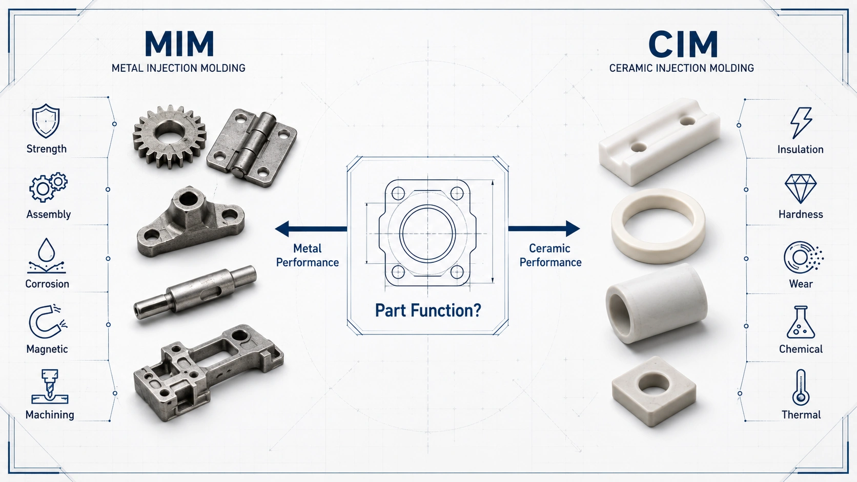
Representative engineering illustration: This graphic explains general MIM-versus-CIM selection logic and is not a specific customer project, production record, or verified test result.
MIM vs CIM Comparison Topics
How Should You Choose Between MIM and CIM?
Choose MIM when the finished component must behave as metal: load-bearing strength, toughness, corrosion resistance, magnetic response, threaded or press-fit assembly, or secondary machining. Choose CIM when it must behave as ceramic: electrical insulation, high hardness, non-metallic wear resistance, chemical stability, thermal resistance, or low metallic contamination.
When reviewing whether a stainless steel MIM part can be replaced with ceramic, compare function zones rather than shape alone. CIM may be suitable where insulation, wear, hardness, chemical exposure, or heat resistance dominate and brittle-fracture, thread, impact, and assembly risks can be controlled. Keep MIM when the part still depends on metallic toughness, ductility, magnetic behavior, thread strength, or mechanical assembly. Review the drawing before selecting metal injection molding or ceramic injection molding.
| Your Part Requires... | Recommended First Review | Why It Matters |
|---|---|---|
| Metallic strength and toughness | MIM | Metal parts usually handle assembly stress, functional load, and movement better than brittle ceramics. |
| Stainless steel, low alloy steel, or special metal performance | MIM | MIM is designed for small complex metal components made from suitable metal powder feedstock. |
| Soft magnetic behavior | MIM | Magnetic performance requires metal material selection and process control. |
| Replacing a metal or stainless steel part with ceramic | Function-zone comparison | Confirm whether the requirement is still metal load-bearing behavior or has shifted toward insulation, hardness, wear, chemical stability, or thermal resistance. |
| Electrical insulation | CIM | Technical ceramics are commonly selected when the component must remain non-conductive. |
| High hardness and non-metallic wear resistance | CIM | Alumina, zirconia, and other ceramics may be suitable when wear and hardness dominate the design. |
| Very low-volume simple geometry | Neither as first choice | CNC machining, ceramic machining, or another prototype route may be more practical before tooling. |
MIM and CIM Share a Process Family, But They Do Not Replace Each Other Automatically
MIM and CIM belong to the broader Powder Injection Molding (PIM) family. Both routes use powder-binder feedstock that can flow into an injection mold, form a green part, remove binder through debinding, and then densify the part through sintering. This shared process structure is why engineers and buyers often compare CIM and MIM components in the same early manufacturing review.
The important difference appears after sintering. MIM starts with metal powder and produces a metal component; CIM starts with ceramic powder and produces a ceramic component. A part shape that appears moldable by both routes may still fail if the selected material behavior does not match the real function. When reviewing whether a stainless steel or other metal MIM part can be changed to ceramic, separate the drawing into function zones: load path, thread or press-fit area, wear surface, insulation requirement, chemical exposure, thermal exposure, critical dimensions, and impact risk. This prevents a process-flow comparison from becoming a wrong material substitution.

Representative engineering illustration: This graphic explains general process relationships and is not a specific customer project, production record, or verified test result.
| Process Factor | MIM | CIM |
|---|---|---|
| Powder type | Fine metal powder | Ceramic powder |
| Binder system | Required to create moldable feedstock | Required to create moldable feedstock |
| Forming method | Injection molding | Injection molding |
| Debinding | Required before metal sintering | Required before ceramic sintering |
| Sintering | Controls density, strength, distortion, and dimensions | Controls ceramic densification, cracking risk, warpage, and surface quality |
| Final material behavior | Metallic | Ceramic |
| Replacement review logic | Keep MIM when the part still needs metallic toughness, thread strength, assembly load, magnetic response, or metal corrosion performance. | Review CIM when the requirement shifts toward insulation, hardness, non-metallic wear resistance, chemical stability, or thermal resistance. |
| Typical decision driver | Strength, toughness, corrosion resistance, magnetic or assembly function | Insulation, hardness, wear resistance, heat resistance, chemical stability |
The Core Difference Is Material Behavior, Not Just Process Name
The most important difference between MIM and CIM is not the molding machine. It is the material behavior after sintering. MIM produces metal parts. Depending on the material grade and process route, MIM parts may be selected for mechanical strength, corrosion resistance, wear resistance, magnetic properties, heat treatment response, or functional assembly.
CIM produces ceramic parts. Ceramic components are often selected when the design requires properties that metals cannot provide well, such as electrical insulation, high hardness, low conductivity, chemical stability, and resistance to certain high-temperature or abrasive environments. But ceramic performance also brings design limits. Ceramic parts are typically more sensitive to tensile stress, impact load, sharp internal corners, chipping, and brittle fracture than metal parts.

Representative engineering illustration: This graphic explains general material-performance differences and is not a specific customer project, production record, or verified test result.
| Requirement | MIM Is Usually Better When... | CIM Is Usually Better When... |
|---|---|---|
| Load-bearing function | The part needs metallic toughness, ductility, or assembly strength. | The load is mainly compressive and ceramic brittleness is acceptable. |
| Electrical behavior | Conductivity or magnetic behavior is required. | Electrical insulation is required. |
| Wear resistance | A hard metal alloy, heat treatment, or surface treatment is suitable. | Non-metallic hardness and ceramic wear resistance are required. |
| Corrosion or chemical exposure | Stainless steel or special alloy performance is suitable. | Metal corrosion, conductivity, or ion release must be avoided. |
| Assembly | Threads, press-fit areas, pins, hinges, or mechanical joints are needed. | The ceramic design avoids impact, tensile loading, and high local stress. |
When Should You Choose MIM?
Choose MIM when the design requires a small, complex metal component with properties that are difficult to achieve economically through CNC machining, casting, stamping, or conventional powder pressing. MIM should be reviewed when geometry complexity and material performance both matter.
MIM is commonly reviewed for parts that need:
- metallic strength and toughness;
- stainless steel, low alloy steel, soft magnetic alloy, or other metal material behavior;
- thin walls, undercuts, micro features, small holes, or complex geometry;
- assembly features such as holes, pins, hinges, gear teeth, slots, or functional surfaces;
- secondary machining, sizing, polishing, coating, passivation, or other post-sintering operations.
MIM selection checklist
- Does the part need metallic strength, toughness, magnetic behavior, or assembly function?
- Is the geometry difficult or wasteful to machine?
- Are critical dimensions and functional surfaces clearly defined?
- Is annual volume high enough to justify tooling and process validation?
- Will secondary operations be needed to meet tolerance, surface, or functional requirements?
For detailed process background, review the MIM process page. For material selection, see MIM materials.
When Should You Choose CIM?
Choose CIM when the design requires a small complex ceramic component that must provide ceramic properties rather than metal properties. CIM is not simply “MIM with ceramic powder.” Ceramic powder behavior, binder removal, ceramic sintering, cracking risk, edge damage, and post-sintering finishing needs may differ from metal injection molded parts.
CIM may be suitable when the part needs:
- electrical insulation;
- high hardness;
- wear resistance;
- chemical stability;
- low metallic contamination risk;
- thermal resistance;
- alumina, zirconia, or other technical ceramic behavior.
CIM selection checklist
- Does the part need electrical insulation or non-metallic behavior?
- Does the part require ceramic hardness, wear resistance, or chemical stability?
- Is brittleness acceptable in the real application environment?
- Are sharp corners, abrupt wall transitions, and thin unsupported sections controlled?
- Are the critical dimensions realistic after ceramic sintering, or will grinding/lapping be needed?
Design Risk Comparison: Ductile Metal Parts vs Brittle Ceramic Parts
The most important DFM difference between MIM and CIM is how the final part responds to stress. MIM parts are metallic, so they are usually more suitable for ductile behavior, threaded assembly, press-fit areas, mechanical engagement, and moderate impact. CIM parts are ceramic, so they are usually better for hardness, insulation, and wear resistance, but they require more careful control of brittle fracture risks.

Representative engineering illustration: This graphic explains general DFM risk patterns and is not a specific customer project, production record, or verified test result.
| Design Feature | MIM Risk | CIM Risk | Engineering Review Focus |
|---|---|---|---|
| Thin wall | Short shot, distortion, weak section | Cracking, breakage, handling damage | Minimum wall thickness, flow path, support strategy |
| Sharp internal corner | Tooling stress, local stress concentration | High crack initiation risk | Add radius where possible |
| Abrupt wall transition | Sink, uneven shrinkage, distortion | Cracking or warpage during debinding/sintering | Smooth transitions and balanced section thickness |
| Thread | Often possible with review or secondary operation | Usually more difficult and fragile | Functional load, machining option, assembly method |
| Long slender shape | Sintering distortion | Warpage and fracture risk | Setter support, orientation, aspect ratio |
| Impact load | Usually more forgiving than CIM | High risk | Confirm real application loading |
Representative Engineering Scenario
Scenario disclosure: This representative engineering scenario explains a common MIM-versus-CIM design conflict. It is not a specific customer project, production record, or verified field case.
Representative problem: A small precision component may initially be reviewed for ceramic injection molding because the design requires high wear resistance, while the same drawing also includes a small threaded feature and a localized assembly load near a sharp internal corner.
Why it can happen: The first comparison may focus on hardness and wear resistance without separating hardness from toughness or reviewing how assembly force travels through the part.
System-level cause: The risk is not only the ceramic material choice. Brittle material behavior, a sharp internal corner, thread loading, and localized assembly stress can combine to create a fracture-sensitive design.
Engineering response: Separate the wear surface from the load-bearing feature. A ceramic option may require added radii, lower stress concentration, and a revised assembly method, while a MIM option should be reviewed for the threaded and load-bearing version.
Prevention: Before tooling, compare MIM and CIM by function zones: wear surface, load path, thread or press-fit area, insulation requirement, critical dimensions, and expected handling or impact conditions.
Process Control Differences: Debinding, Sintering, Shrinkage, and Defects
Both MIM and CIM require binder removal and sintering, but their quality risks should not be treated as identical. In MIM, debinding and sintering must support final density, dimensional stability, strength, and surface condition. In CIM, debinding and ceramic sintering must be controlled to avoid cracking, chipping, warpage, surface defects, and brittle failure.

Representative engineering illustration: This graphic explains general process-control risks and is not a specific customer project, production record, or verified test result.
| Issue | MIM Concern | CIM Concern | What to Review Before Tooling |
|---|---|---|---|
| Warpage | Uneven shrinkage, poor support, geometry imbalance | Uneven sintering, weak ceramic section, poor support | Wall transition, setter support, critical flatness |
| Cracking | Possible from molding, debinding, or sintering stress | More sensitive due to ceramic brittleness | Sharp corners, thin walls, stress concentration |
| Dimensional drift | Shrinkage variation, secondary operation allowance | Sintering variation, grinding allowance | Critical dimensions and inspection strategy |
| Surface defect | Gate mark, sintering surface, polishing need | Chips, cracks, ceramic surface flaws | Functional surfaces and acceptable finish |
| Yield risk | Distortion, tolerance, secondary operations | Cracking, warpage, handling damage | Early DFM review before tooling |
Tolerance and Inspection: What Should Be Confirmed Before RFQ?
MIM and CIM are both near-net-shape processes, but neither should be sold with vague claims such as “perfect precision.” Tolerance capability depends on material, part size, geometry, sintering behavior, feature location, inspection method, and whether secondary operations are allowed.
For MIM, tight dimensions may require tooling compensation, sizing, machining, grinding, or process capability validation. For CIM, tight ceramic dimensions may require grinding, lapping, polishing, or additional inspection after sintering. For extremely tight ceramic dimensions, the engineering plan often depends on post-sintering grinding or lapping rather than relying only on as-sintered geometry. In both cases, critical dimensions should be identified before tooling because they influence shrinkage compensation, mold design, finishing allowance, inspection fixture planning, and cost.
| RFQ Input | Why It Matters |
|---|---|
| 2D drawing with tolerances | Defines acceptance criteria and inspection scope. |
| 3D CAD model | Helps review moldability, shrinkage, feature access, and tooling risk. |
| Critical dimensions | Guides tooling compensation and inspection planning. |
| Functional surfaces | Helps determine whether polishing, grinding, or machining is required. |
| Application load | Helps decide whether metal or ceramic behavior is suitable. |
| Surface finish requirement | Affects finishing process, cost, and inspection. |
| Annual volume | Affects tooling justification and production economics. |
SQE Inspection Focus
| Inspection Area | MIM Focus | CIM Focus |
|---|---|---|
| Dimensions | Critical dimensions, shrinkage compensation, machining allowance | Warpage, grinding allowance, critical ceramic dimensions |
| Surface | Gate mark, sintering surface, finishing quality | Chips, cracks, surface flaws, edge damage |
| Functional performance | Assembly fit, load, corrosion, magnetic behavior | Insulation, wear, chemical stability, thermal exposure |
| Defects | Short shot, distortion, density issue | Cracking, warpage, brittle fracture |
Cost Comparison: Why MIM and CIM Costs Depend on Different Drivers
MIM is not automatically cheaper than CIM, and CIM is not automatically more expensive than MIM. The correct comparison is not only unit price. The better comparison is total project risk, including tooling, material, yield, finishing, inspection, and production volume.
| Cost Driver | MIM | CIM |
|---|---|---|
| Tooling | Required; justified by volume and geometry complexity | Required; justified by volume and ceramic geometry complexity |
| Powder material | Depends on metal grade and alloy requirement | Depends on ceramic powder type, purity, and performance requirement |
| Debinding and sintering | Required; affects density, strength, and dimensions | Required; affects cracking, warpage, and ceramic properties |
| Secondary operations | Machining, sizing, heat treatment, polishing, coating, passivation | Grinding, lapping, polishing, edge control, ceramic finishing |
| Yield risk | Distortion, dimensional variation, density, surface condition | Cracking, brittle fracture, warpage, handling damage |
| Best cost logic | Complex small metal parts at suitable volume | Complex small ceramic parts at suitable volume |
Application Comparison: Which Parts Fit MIM or CIM Better?
MIM and CIM should be compared by part function rather than industry name alone. The same industry may use both metal and ceramic parts, but for different reasons. A medical, electronics, automotive, or industrial device may contain both MIM and CIM components; the deciding factor is what each component must do.
| Application Need | MIM Better Fit | CIM Better Fit |
|---|---|---|
| Small structural metal bracket | Yes | Usually no |
| Miniature metal gear | Often yes | Only if ceramic wear or insulation is the reason |
| Precision hinge or shaft | Usually yes | Usually no |
| Electrical insulation component | No | Yes |
| Ceramic guide or wear insert | Usually no | Yes |
| Soft magnetic part | Yes | No |
| Threaded assembly part | Usually yes | Usually not first choice |
| Chemical-resistant non-metallic part | Not usually first choice | Often yes |
When Neither MIM Nor CIM May Be the Best Option
A useful process comparison should also explain when neither route is the best first choice. MIM and CIM are powerful processes, but they are not universal solutions. If the part is simple, large, very low-volume, or still changing, tooling-based powder injection molding may create unnecessary cost and validation risk.
| Situation | Better First Review |
|---|---|
| Very low-volume simple metal part | CNC machining or prototype machining |
| Large simple metal structure | Casting, forging, machining, or fabrication |
| Simple flat sheet metal geometry | Stamping or laser cutting |
| Large simple ceramic part | Ceramic pressing or ceramic machining |
| Loose-tolerance porous metal part | Conventional powder metallurgy |
| Design still changing frequently | Prototype route before injection mold investment |
Common Mistakes When Comparing MIM and CIM
| Mistake | Risk | Better Review Approach |
|---|---|---|
| Comparing only process flow | Wrong material selection | Start from required final part behavior. |
| Assuming CIM is stronger because it is harder | Brittle failure under impact or tension | Separate hardness, toughness, wear, and load requirements. |
| Choosing MIM when insulation is required | Functional failure | Review electrical, thermal, and environmental requirements. |
| Choosing CIM for threaded or impact-loaded parts without review | Cracking or assembly failure | Review load path, radius, and assembly method. |
| Ignoring sintering shrinkage | Dimensional failure | Identify critical dimensions before tooling. |
| Sending RFQ without application details | Inaccurate quote and weak DFM review | Provide drawing, material, tolerance, surface, load, and volume information. |

Representative engineering illustration: This graphic explains general project-review inputs and is not a specific customer project, production record, or verified test result.
What Information Should You Send for MIM or CIM Project Review?
For a useful MIM or CIM suitability review, prepare more than a part name. The engineering team needs enough information to judge material behavior, moldability, sintering risk, dimensional control, post-processing needs, and inspection requirements.
Project review input checklist
- 2D drawing with tolerances;
- 3D CAD file;
- preferred material or required performance;
- critical dimensions and functional surfaces;
- surface finish requirement;
- application environment;
- load, wear, insulation, corrosion, or thermal requirements;
- expected annual volume;
- current manufacturing process if replacing CNC, casting, stamping, pressing, or ceramic machining.
Engineering review direction
Send your drawing, 3D file, material requirement, tolerance needs, surface requirement, application environment, and estimated annual volume. XTMIM can review whether MIM or CIM is more suitable before tooling, and help identify manufacturability risks such as shrinkage, cracking, warpage, finishing allowance, and inspection requirements.
FAQ: MIM vs CIM
What is the main difference between MIM and CIM?
The main difference is the final material behavior. MIM uses metal powder and binder to produce metal parts after debinding and sintering. CIM uses ceramic powder and binder to produce ceramic parts. MIM is usually selected for metallic strength, toughness, corrosion resistance, magnetic behavior, and assembly function. CIM is usually selected for electrical insulation, hardness, wear resistance, chemical stability, and non-metallic performance.
Are MIM and CIM the same process?
They are related but not the same. Both belong to the powder injection molding family and share similar steps such as feedstock preparation, injection molding, debinding, and sintering. However, MIM produces metal parts and CIM produces ceramic parts, so their material behavior, design risks, sintering control, finishing methods, and inspection concerns are different.
Is CIM stronger than MIM?
Not in a simple general sense. Ceramic materials can be very hard and wear resistant, but they are also more sensitive to brittle fracture, impact, sharp corners, and tensile stress. MIM metal parts are often better for load-bearing, threaded assembly, and mechanical function. The better choice depends on whether the part needs metallic toughness or ceramic hardness and insulation.
When should I choose MIM instead of CIM?
Choose MIM when the part needs metal performance, such as strength, toughness, corrosion resistance, magnetic behavior, heat treatment response, threaded assembly, or secondary machining. MIM is also suitable for small complex metal parts where CNC machining, casting, stamping, or conventional PM may be inefficient.
When should I choose CIM instead of MIM?
Choose CIM when the part needs ceramic properties, such as electrical insulation, high hardness, wear resistance, chemical stability, thermal resistance, or non-metallic behavior. CIM is commonly reviewed for small complex alumina, zirconia, or technical ceramic parts where conventional ceramic machining or pressing is difficult.
Can the same drawing be reviewed for both MIM and CIM?
Yes. The same drawing can be reviewed for both MIM and CIM when the part function is not yet fixed or when the buyer is comparing metal and ceramic performance. The review should check material behavior, load path, insulation or wear requirements, critical dimensions, surface finish, post-sintering operations, tooling risk, and expected annual volume before choosing the process route.
What should I provide for a MIM or CIM quotation?
Provide a 2D drawing, 3D CAD file, material requirement, critical dimensions, tolerances, surface finish requirement, application environment, expected annual volume, and any load, wear, insulation, corrosion, or thermal requirements. This allows the engineering team to review whether MIM or CIM is more suitable before tooling.
Standards and Engineering Reference Note
MIM and CIM process selection should be based on drawing-level engineering review, not on generic process claims. For MIM material specification, MPIF Standard 35-MIM is a relevant industry reference for common MIM materials and explanatory information.
For general powder injection molding terminology, industry references describe PIM as a process family that includes MIM for metals and CIM for ceramics. Additional background can be reviewed through MIMA, PIM International, and CIM-related technical references such as ceramic injection moulding resources.
CIM suitability should be confirmed through ceramic material data, application-specific electrical, thermal, wear, and chemical requirements, post-sintering finishing needs, and supplier process capability. Final material selection, tolerance strategy, inspection requirements, and acceptance criteria should follow the buyer’s drawing, applicable material data, supplier process capability, and any project-specific standards required by the customer.