MIM Process Selection Insights Quick Answer Powder injection molding, usually abbreviated as PIM, is a manufacturing process family that combines powder-based feedstock with injection molding, debinding, and sintering. Metal injection molding (MIM) is the metal route within PIM, while ceramic injection molding (CIM) is the ceramic route. They share the same high-level process logic, but …
MIM Process Selection Insights
Quick Answer
Powder injection molding, usually abbreviated as PIM, is a manufacturing process family that combines powder-based feedstock with injection molding, debinding, and sintering. Metal injection molding (MIM) is the metal route within PIM, while ceramic injection molding (CIM) is the ceramic route. They share the same high-level process logic, but material behavior, tooling, furnace conditions, contamination control, shrinkage, handling, and inspection require route-specific validation.
Route selection begins with the required final material function, then confirms geometry, feedstock, tooling, debinding, sintering, contamination control, and inspection. XTMIM can review both MIM and CIM routes from the drawing and operating requirements.
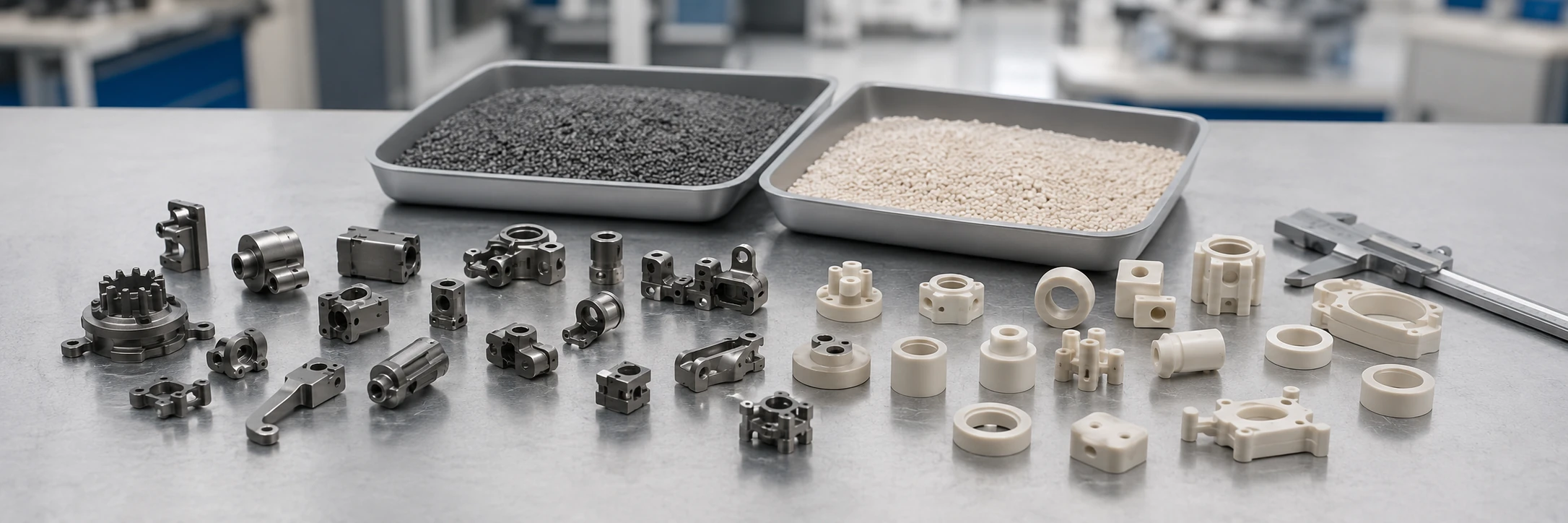
Engineering takeaway: PIM is the parent process family, while MIM and CIM lead to different final material systems.
What Is Powder Injection Molding?
Powder injection molding is a manufacturing route for producing geometrically complex parts from a powder-based material system. It combines a moldable powder-binder feedstock with injection molding, debinding, and sintering.
Fine powder is combined with a binder to create a moldable feedstock. That feedstock is injected into a mold cavity, cooled, and removed as a green part. The binder is then removed, and the remaining powder structure is densified during sintering.
PIM should be understood as a process family rather than one specific material route. The term describes the combination of powder processing and injection molding, but it does not by itself identify whether the final component is metal or ceramic. This is why PIM appears naturally within the wider discussion of related manufacturing processes.
Metal route
Metal Injection Molding
Metal powder is processed into a sintered metal component when the application requires metallic behavior.
Ceramic route
Ceramic Injection Molding
Ceramic powder is processed into a sintered technical ceramic component when the application requires ceramic behavior.
Why the Full Term Matters
The abbreviation PIM is also used outside manufacturing. In project documents, searches, RFQs, and supplier discussions, it is safer to write Powder Injection Molding (PIM) at the first mention. The British spelling, powder injection moulding, refers to the same process family. The full term also prevents another common mistake: treating PIM and MIM as interchangeable. MIM is part of PIM, but PIM is broader than MIM.
How MIM and CIM Fit Within the PIM Process Family
MIM and CIM are parallel branches of powder injection molding. Neither is a processing step inside the other.
| Process Term | Role | Powder System | Final Component | First Selection Question |
|---|---|---|---|---|
| Powder Injection Molding | Parent process family | Metal or ceramic powder combined with binder | Depends on the selected route | Which final material system does the application require? |
| Metal Injection Molding | Metal route within PIM | Metal powder feedstock | Sintered metal component | Does the application require metallic behavior? |
| Ceramic Injection Molding | Ceramic route within PIM | Ceramic powder feedstock | Sintered technical ceramic component | Does the application require technical ceramic behavior? |
Metal Injection Molding as the Metal Route
MIM is relevant when the final component needs properties associated with metal, such as strength, toughness, electrical or thermal conductivity, magnetic response, heat-treatable behavior, metal joining, or a metallic surface finish.
The geometry must still be suitable for molding, debinding, sintering, and inspection. A metal requirement alone does not automatically make a component a suitable MIM part.
Ceramic Injection Molding as the Ceramic Route
CIM is relevant when the final component requires the functional behavior of a technical ceramic. Depending on the material system and application, this may include electrical insulation, hardness, wear resistance, high-temperature stability, chemical resistance, or dimensional stability under a specific service condition.
CIM suitability also depends on geometry, wall balance, molding behavior, handling, debinding, shrinkage, support strategy, surface requirements, and the risk of chipping or cracking. For a process-level review of ceramic materials, molding, debinding, sintering, finishing, design risks, and project feasibility, see the Ceramic Injection Molding process guide.

Engineering takeaway: MIM and CIM both use feedstock, molding, debinding and sintering, but the material systems and validated controls are different.
Shared Equipment Does Not Mean Identical Process Control
MIM and CIM may use the same core categories of equipment. Equipment-category overlap does not mean every material can use the same setup, tooling details, furnace conditions, or inspection plan.
| Shared Stage or Equipment Category | Common Process Role | Why MIM and CIM Still Need Different Controls |
|---|---|---|
| Feedstock preparation | Combine powder and binder into moldable material | Powder chemistry, abrasion, loading level, binder compatibility, and contamination sensitivity differ. |
| Injection molding | Fill a mold cavity and form a green part | Flow behavior, temperature window, pressure response, wear, moisture, and green strength can differ. |
| Mold and tooling | Define geometry and compensate for shrinkage | Shrinkage, venting, gate strategy, surface condition, ejection risk, and tool wear may differ. |
| Debinding equipment | Remove binder before sintering | Binder systems and acceptable solvent, catalytic, or thermal routes may differ. |
| Sintering furnace | Densify the powder structure | Atmosphere, temperature capability, thermal cycle, setter material, and contamination limits may differ. |
| Inspection equipment | Verify dimensions and condition | Metal and ceramic parts may require different material, surface, damage, and acceptance checks. |
Injection Equipment and Feedstock Behavior
Metal and ceramic feedstocks can both be injection molded, but they may not respond identically to shear, temperature, residence time, pressure, cooling, or moisture. Ceramic powders can also be highly abrasive. Tooling materials, screws, barrels, nozzles, runners, and gates may require additional wear consideration.
Debinding Route Compatibility
A debinding system must be compatible with the binder formulation. A furnace or solvent system that supports one feedstock does not automatically support every other binder route.
- Binder type and removal mechanism;
- Maximum section thickness and binder-removal path;
- Green-part strength during transfer;
- Temperature and atmosphere requirements;
- Support or spacing needs;
- Residual-carbon or contamination risk.
Sintering Atmosphere and Thermal Cycle
Metal and ceramic systems can require different sintering environments. The furnace must be evaluated for more than maximum temperature. Atmosphere compatibility, hot-zone materials, previous furnace use, loading method, dimensional support, chemical interaction, and cleaning procedures may all matter.
Contamination, Tooling, Handling, and Inspection
Shared equipment requires a controlled changeover strategy. Residual metal, ceramic, binder, lubricant, setter material, or furnace deposits can affect surface condition, chemistry, color, densification, or subsequent processing. Metal and ceramic components may also need different acceptance logic after sintering.
Engineering takeaway: MIM and CIM may share the same core equipment categories, but each material system still needs a validated feedstock, tooling, debinding, sintering, contamination-control, handling, and inspection plan.

Engineering takeaway: Equipment compatibility must be confirmed through feedstock, tooling, cleaning, atmosphere, thermal-cycle and contamination-control review.
PIM Route Triage: Metal, Ceramic, or More Review?
PIM is the parent process family. The early task is not to complete a full MIM-versus-CIM comparison, but to identify which material route deserves detailed review and whether enough project evidence exists to continue.
| Review Question | MIM Route Signal | CIM Route Signal | Hold for Clarification |
|---|---|---|---|
| What must the final material provide? | Metallic strength, toughness, conductivity, magnetic response, heat treatment, joining, or a metallic surface route | Electrical insulation, hardness, wear resistance, ceramic thermal behavior, or chemical stability | The required material function is undefined, conflicting, or described only by a broad material name |
| Can the geometry pass through the PIM sequence? | Compact metal geometry can be molded, ejected, debound, sintered, supported, and inspected | Compact ceramic geometry can be molded, handled, debound, sintered, protected, and inspected | Wall balance, unsupported features, ejection, binder removal, shrinkage, or acceptance risk remains unresolved |
| Is the project mature enough for route review? | Drawing, metal function, critical dimensions, annual volume, finishing, and inspection needs are available | Drawing, ceramic function, critical dimensions, annual volume, surface or edge limits, and inspection needs are available | The design is changing, the volume case is unclear, or measurable acceptance criteria are missing |
A metal requirement should continue into detailed metal injection molding review. A technical ceramic requirement should continue into detailed ceramic injection molding review. For a full side-by-side comparison of materials, design limits, finishing, and route tradeoffs, use the dedicated MIM vs CIM page.

Engineering takeaway: Similar geometry can enter different PIM routes when the required metallic or technical ceramic behavior changes.
Representative Engineering Scenario
A compact part with thin walls, cross-holes, and an internal profile may appear moldable through either route. Metallic load-bearing, conductivity, magnetic response, heat treatment, or metal joining points toward MIM. Electrical insulation, ceramic hardness, wear resistance, or chemical stability points toward CIM. If the required function or acceptance criteria remain unclear, the route should stay on hold.
This is a representative engineering scenario, not a production claim. It illustrates route triage rather than a complete MIM-versus-CIM comparison.
PIM Route Hold Gates Before Tooling
A project should not move from a broad “PIM looks possible” discussion into tooling until the material route, process constraints, acceptance plan, and missing evidence have been reviewed. The following hold gates help separate an early route direction from a tooling-ready decision.
| Hold Gate | Evidence Needed | Hold the Project If | Why It Matters |
|---|---|---|---|
| 1. Final material function | Required strength, toughness, conductivity, insulation, wear, chemical, thermal, magnetic, joining, or surface behavior | The request only names “metal,” “ceramic,” or “PIM” without defining the required function | The material function determines whether the project belongs in MIM, CIM, or another route. |
| 2. Feedstock and binder route | Target material family, available feedstock route, binder-removal method, section-thickness review, and handling limits | The selected material has no confirmed feedstock path or debinding compatibility | A moldable geometry is not enough if the feedstock cannot be processed and debound safely. |
| 3. Geometry and mold release | 3D model, draft, wall balance, gates, vents, undercuts, ejection surfaces, and green-part support | Critical features cannot fill, eject, or survive green-part handling without redesign | Many route failures begin before sintering, during filling, ejection, or transfer. |
| 4. Shrinkage and tooling strategy | Critical datums, shrinkage direction, tool-compensation plan, support strategy, and dimensions reserved for finishing | The drawing assumes one nominal scale factor or machining-level tolerance on nearly every feature | Sintering shrinkage is material-, geometry-, tooling-, loading-, and furnace-dependent. |
| 5. Furnace and contamination compatibility | Atmosphere, temperature capability, setter and fixture compatibility, cleaning plan, and material-contact review | Shared equipment is assumed to be acceptable without route-specific compatibility checks | Equipment category overlap does not prove atmosphere, hot-zone, setter, or contamination compatibility. |
| 6. Inspection and acceptance plan | Critical dimensions, surface limits, edge condition, material verification, functional tests, and sampling expectations | The RFQ contains broad quality language but no measurable acceptance criteria | MIM and CIM may require different dimensional, surface, damage, material, and functional checks. |
| 7. Volume and project maturity | Annual volume, design-release status, expected life, current process, and reason for changing routes | The design is still changing frequently or the volume does not justify tooling and validation | PIM is normally a production process decision, not only a geometry demonstration. |
Tooling release rule: A project may have a clear MIM or CIM direction while still remaining on hold. Route direction answers “which process family should be reviewed”; tooling release requires enough evidence to define material, geometry, shrinkage, furnace, inspection, and commercial assumptions.
Common Early Route-Selection Mistakes
| Early Mistake | Why It Creates Risk | Engineering Review Action |
|---|---|---|
| Selecting MIM or CIM from geometry alone | Similar geometry can require very different material behavior, finishing, and inspection. | Define the final material function and service environment before route selection. |
| Assuming shared equipment means identical process settings | Feedstock, binder, atmosphere, setters, contamination limits, and thermal cycles may differ. | Review compatibility at each contact, debinding, and sintering stage. |
| Using only a broad material name | A name such as “stainless steel” or “ceramic” does not define the required property, grade, or acceptance criteria. | Provide the required function, target material family, environment, and measurable performance needs. |
| Releasing tooling before the inspection plan is defined | Critical datums, edge limits, finishing allowances, and acceptance methods may not match the mold and sintering plan. | Lock the measurable CTQs and inspection approach before tool compensation is finalized. |
What to Send for a PIM Route Review
A useful PIM review should begin with more than a part image and a material name. The project team needs enough information to determine whether the component should proceed through MIM, CIM, or another manufacturing route.
| Information to Provide | Why It Matters |
|---|---|
| 2D drawing | Defines dimensions, tolerances, datums, surfaces, notes, and acceptance requirements. |
| 3D CAD file | Supports geometry, wall, undercut, feature, tooling, and mold-release review. |
| Target material | Provides an initial metal or ceramic route direction. |
| Required material function | Helps when the exact material grade has not yet been selected. |
| Operating environment | Clarifies load, temperature, wear, corrosion, chemical, electrical, and assembly conditions. |
| Critical dimensions and tolerances | Identifies where shrinkage control, tooling compensation, finishing, or special inspection may be needed. |
| Surface and edge requirements | Supports review of gate marks, parting lines, polishing, edge protection, coatings, and appearance. |
| Estimated annual volume | Supports tooling, qualification, equipment planning, and economic review. |
| Current manufacturing route | Shows whether the project is moving from machining, pressing, casting, forming, or another process. |
| Current quality or cost problem | Helps focus the review on the reason for changing the process. |
| Project stage | Distinguishes concept review, prototype validation, tooling release, transfer, and production sourcing. |
What an Early Review Can Confirm—and What Still Needs Validation
Can be screened early
Drawing and Route Review Outputs
- Whether the required function points toward MIM, CIM, or another process;
- Which geometry features create filling, ejection, handling, debinding, or sintering risk;
- Which project inputs or acceptance criteria are still missing;
- Which dimensions may need finishing rather than relying only on as-sintered control;
- Which equipment, atmosphere, setter, contamination, and inspection questions require validation.
Requires validation
Production Claims That Should Remain Open
- Final shrinkage compensation and tool-correction values;
- Production capability for every tolerance and surface requirement;
- Final material properties after the selected process route;
- Debinding and sintering cycle settings;
- Final unit cost, tooling life, process yield, and qualification result.
This separation prevents an early process-selection discussion from being mistaken for a final manufacturing guarantee. Tooling trials and validation remain necessary before production capability and acceptance criteria are confirmed.

Engineering takeaway: A useful PIM review requires drawings, material function, operating conditions, critical dimensions, annual volume and acceptance requirements.
Request a PIM Route Review
Send the 2D drawing, 3D CAD file, target material or required material function, application environment, critical dimensions, surface requirements, annual volume, current manufacturing route, and known quality concerns.
- Review whether the project is aligned with MIM or CIM;
- Identify whether another process should remain under consideration;
- Clarify geometry, material, shrinkage, handling, and inspection questions;
- Define what additional information is required before tooling or quotation.
A route review is an engineering starting point. Final feasibility, performance, dimensional capability, production cost, and acceptance criteria must be confirmed against the actual drawing, material system, process plan, tooling design, and validation results.
FAQ About Powder Injection Molding, MIM, and CIM
What does PIM mean in manufacturing?
PIM means Powder Injection Molding. It is a manufacturing process family that combines powder-based feedstock, injection molding, debinding, and sintering. MIM and CIM are two major routes within PIM.
How are MIM and CIM related within PIM?
MIM and CIM are parallel branches within the broader Powder Injection Molding process family. MIM is the metal route and CIM is the ceramic route. CIM is not a type of MIM, and both routes require material-specific process controls.
Can MIM and CIM use the same manufacturing equipment?
They may use the same core categories of equipment, such as injection molding machines, debinding systems, and sintering furnaces. However, material compatibility, tooling, binder route, atmosphere, thermal cycle, cleaning, contamination control, fixtures, and inspection must be validated separately.
What is the main difference between MIM and CIM?
The main difference is the final material system. MIM produces sintered metal components. CIM produces sintered technical ceramic components. That material difference changes feedstock behavior, tooling, processing, handling, finishing, and inspection requirements.
What information is needed to choose between MIM and CIM?
Provide the drawing, 3D model, required material or material function, operating environment, critical dimensions, tolerance requirements, surface expectations, annual volume, current process, and project stage.
Is powder injection molding the same as conventional powder metallurgy?
No. Powder injection molding uses a moldable powder-binder feedstock and injection molding to create complex green parts before debinding and sintering. Conventional press-and-sinter powder metallurgy forms powder through compaction and usually follows different geometry and tooling constraints.
Technical References
The following industry resources support the process-family terminology and the shared feedstock, molding, debinding, and sintering framework used in this guide. Project feasibility still requires drawing-specific and material-specific validation.
Industry education
MPIF PIM Tutorial
The Metal Powder Industries Federation tutorial covers PIM materials and binders, injection molding, debinding, sintering, part design, cost, facilities, and market considerations.
Process terminology
PIM International: MIM and CIM
This industry overview describes Powder Injection Molding as the process family comprising Metal Injection Molding and Ceramic Injection Molding.