Micro MIM Engineering SummaryMicro MIM Engineering Guide Quick Answer: The micro MIM process is not simply conventional metal injection molding applied to a smaller CAD model. A practical project may involve a complete micro part, a larger part containing microfeatures, or a component whose critical dimensions and positions must be controlled at a micro scale. …
Micro MIM Engineering Summary
Micro MIM Engineering Guide
Quick Answer: The micro MIM process is not simply conventional metal injection molding applied to a smaller CAD model. A practical project may involve a complete micro part, a larger part containing microfeatures, or a component whose critical dimensions and positions must be controlled at a micro scale. As geometry becomes smaller, powder size, feedstock flow, mold replication, green-part strength, debinding support, sintering movement, and measurement capability become more tightly connected. The engineering value is not a universal minimum-feature claim; it is a feature-by-feature decision on whether the bore, slot, tooth, wall, edge, datum, and inspection method can remain stable through the complete process chain. This review is most useful when a drawing contains scale-sensitive geometry, tight positional relationships, or features that cannot be inspected conventionally. Before quotation or formal tooling, submit the 3D model, 2D drawing, material, annual volume, critical features, allowed secondary operations, and inspection requirements for a tooling-readiness review.
Engineering boundary: This guide does not publish a universal minimum feature size or claim a fixed Micro MIM tolerance. Published experimental dimensions depend on the material, powder, feedstock, tooling, geometry, process window, sintering route, and measurement method used for that specific study.
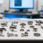
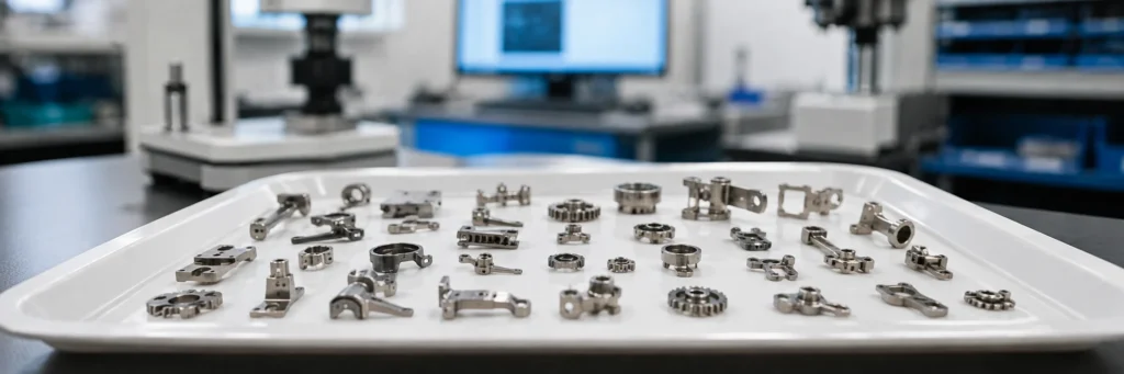
Representative engineering illustration: The parts and review setup illustrate Micro MIM engineering considerations and do not represent a customer project or guaranteed XTMIM capability.
What Is Micro MIM and When Does a Part Enter the Micro Scale?
Micro MIM, also written as micro metal injection molding or μ-MIM, applies powder-based injection molding to very small metal components or to components that contain scale-sensitive features. The general route still includes a powder-binder feedstock, injection molding, debinding, and sintering. The difference is that a small change in a bore, slot, tooth, wall, edge, or feature position can consume a much larger share of the available tolerance.
The first review should therefore determine what the word micro describes. It may describe the complete component, a local feature, or a dimensional relationship. These cases do not create the same tooling, process, or inspection problem.
| Project Type | What “Micro” Describes | Main Review Priority |
|---|---|---|
| Complete micro part | The complete component is very small. | Handling, orientation, ejection, and measurement. |
| Microstructured part | The component contains small local holes, slots, teeth, ribs, textures, or pillars. | Feature replication, mold release, and shape retention. |
| Micro-precision part | A critical dimensional or positional relationship operates at micro scale. | Datum control, compensation, and measurement uncertainty. |
Technical evidence note: Attia and Alcock’s review of micro-powder injection moulding distinguishes complete microcomponents from parts containing microstructured features and describes tooling, feedstock, process, and metrology limitations as connected constraints. That supports a scale-sensitive risk definition rather than one universal outside dimension. Review the published paper record.
Why There Is No Universal Micro MIM Size Threshold
A single external dimension, weight, or nominal wall thickness cannot define every Micro MIM project. The answer also depends on the smallest local feature, feature depth and aspect ratio, powder size and distribution, feedstock rheology, gate location, mold-insert manufacturing, release direction, green-part strength, sintering orientation, tolerance, and inspection access.
For example, a shallow open slot and a deep blind slot may have the same nominal width but very different filling, venting, release, and inspection risks. A short through-hole and a deep blind bore may have the same diameter but require different cores, different demolding conditions, and different measurement methods.
Signals That Trigger a Micro MIM Review
| Review Trigger | Why It Matters |
|---|---|
| A feature is small relative to the selected powder. | Powder movement and edge replication may become unstable. |
| A bore requires a slender molded core. | Core deflection, wear, breakage, and withdrawal become significant. |
| A thin section is far from the gate. | The feedstock may freeze before the section fills completely. |
| Fine teeth, pillars, or thin edges have limited support. | Ejection and Green Part handling may damage the feature. |
| A small absolute shift consumes much of the tolerance. | Sintering variation becomes functionally significant. |
| The feature cannot be reached by a conventional probe. | The drawing may lack a production inspection route. |
| Several microfeatures interact. | Tooling, filling, demolding, sintering, and inspection risks become coupled. |
For broader rules covering conventional part geometry, wall thickness, gates, shrinkage, and tolerances, use the MIM Design Guide. For a commercial fit review focused on size, annual volume, tolerance, and machining reduction, use the guide to small complex MIM parts.
Micro MIM Feature Limits: Holes, Slots, Teeth, Walls, and Fine Details
The phrase “minimum Micro MIM feature” is often misleading because different feature types fail for different reasons. A small external rib is formed by a recess in the mold. A small hole requires a core. A fine texture depends on mold-surface replication. A narrow channel may involve filling, venting, release, and inspection restrictions at the same time.
Feature feasibility therefore needs to be reviewed by geometry rather than by one published minimum number.
Why Minimum Feature Size Is Not a Single Number
A feature review should consider width or diameter, depth or height, aspect ratio, adjacent wall support, flow direction, release direction, final dimensional relationship, and measurement access. A narrow shallow groove may be less difficult than a wider groove with a high depth-to-width ratio. A pillar may fill successfully but remain too weak to survive ejection. A bore may form but move enough during sintering to miss its positional requirement.
Micro Holes and Small Cores
A molded micro bore is usually created by a core pin or insert. The review should include core length, unsupported span, stiffness under injection pressure, alignment, feedstock flow around the core, air release as the flow fronts meet, Green Part shrinkage onto the core, withdrawal friction, final hole size, roundness, position, and inspection access.
A hole is not production-ready merely because the toolmaker can manufacture the core. The core must remain stable through repeated molding cycles, allow the Green Part to release without cracking, and produce a sintered feature that can be inspected using an agreed method. Conventional geometry rules that still apply before these micro-scale effects are reviewed in the MIM holes, slots, and undercuts design guide.
Narrow Slots and Channels
Narrow slots require the inverse wall or insert to be produced in the mold while the feedstock reaches the complete slot length and displaces trapped air. Review slot width and depth, open or blind geometry, end radius, distance from the gate, local wall thickness, venting, draft, release friction, and the final opening after sintering.
Micro Teeth and Fine Profiles
Micro teeth combine mold manufacturing, filling, release, sintering, and profile inspection. The root may be the last region to fill. The tip may become rounded because of tooling radius, incomplete replication, mold wear, or sintering. A tooth can remain visibly present while its thickness, pitch, profile, or relationship to a center bore moves outside the functional requirement.
For a gear-specific review covering tooth profile, bore-to-tooth concentricity, material, secondary operations, and RFQ inputs, use the dedicated MIM micro gears page.
Thin Walls, Ribs, Pins, and Pillars
Thin sections can freeze quickly during filling, particularly after a thicker region or at the end of a long flow path. Once molded, the same section may be vulnerable during ejection, tray loading, debinding, and sintering. Tall ribs, fine pins, and micro pillars may underfill at the top, fracture during handling, lose support during debinding, or tilt and round during sintering.
Sharp Corners and Fine Surface Textures
A CAD model can contain a mathematically sharp corner, but the mold insert must be produced by a real machining, EDM, laser, electroforming, or other tooling route. The tooling method introduces its own radius, surface condition, and dimensional limits. Molding and sintering may soften the edge further. The drawing should distinguish between a visually preferred sharp edge and a truly functional edge.
| Feature | Main Tooling Risk | Main Process Risk | Acceptance Question |
|---|---|---|---|
| Micro bore | Slender core deflection or wear | Weld line, withdrawal damage, or bore movement | Can diameter, roundness, and position be measured? |
| Narrow slot | Thin insert and venting difficulty | Incomplete end filling and sidewall drag | Can the full depth and opening be verified? |
| Fine tooth | Tool radius and wear | Root underfill and tip rounding | Is profile inspection available? |
| Thin wall | Difficult flow path | Freeze-off, handling damage, and warpage | Can thickness or functional performance be verified? |
| Micro pillar | Small mold recess | Underfill, fracture, and tilting | Can it be fixtured without damage? |
| Fine texture | Mold-surface manufacturing | Incomplete replication and wear change | Is acceptance visual, dimensional, or functional? |

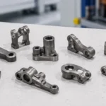
Representative engineering illustration: The geometries are generic Micro MIM review examples and are not actual customer parts or published XTMIM minimum-feature limits.
Powder and Feedstock Requirements for Micro MIM
Micro MIM feedstock contains metal powder and a multi-component binder system. During molding, the binder allows the powder-filled material to flow. After molding, it supports the Green Part until it is progressively removed. At micro scale, the feedstock must enter narrow cavities, keep powder distributed uniformly, create enough Green Part strength, release from the mold, debind without losing shape, and sinter with predictable dimensional behavior.
Powder Size Relative to Feature Size
Metal powder is made of discrete particles. As a slot, edge, texture, or cavity becomes smaller, the particles occupy a larger proportion of the geometry. Particle size, distribution, and shape influence how the feedstock enters the feature and how accurately the mold surface can be replicated.
This does not mean the smallest available powder is automatically the correct choice. Reducing particle size can change surface area, binder demand, viscosity, powder loading, oxidation sensitivity, dispersion, debinding behavior, and sintering activity.
Research evidence: Okubo, Tanaka, and Ito examined the effect of metal-powder particle size and particle-size distribution on dimensional accuracy in micro metal injection molding. The practical conclusion is not that one powder size guarantees a result, but that powder characteristics must be evaluated against the actual feature, feedstock, tooling, and process route. View the research record.
Particle Distribution, Solid Loading, and Rheology
A practical powder system contains a distribution of particle sizes rather than one perfectly uniform particle. Distribution and morphology affect packing, flow, surface quality, and sintering. Solid loading must remain high enough for dimensional stability but not so high that the feedstock becomes difficult to mold.
Lower viscosity can help cavity filling, but a low-viscosity value alone does not prove suitability. The feedstock must still resist powder-binder separation and produce a Green Part that can be handled without damage.
Powder–Binder Separation Risk
A sudden section change, very small gate, high local shear, or long narrow path can cause powder and binder to move differently. Local composition variation may later affect shrinkage, warpage, surface condition, local porosity, dimensional repeatability, and mechanical performance even when the Green Part appears complete.
Commercial Feedstock Suitability
XTMIM uses externally sourced pelletized MIM feedstock. A Micro MIM inquiry should therefore begin by checking whether an available commercial feedstock is compatible with the alloy, smallest feature, tooling route, injection process, debinding route, sintering requirement, and inspection plan.
This page does not imply that XTMIM atomizes powder, formulates all binders internally, or routinely supplies proprietary submicron Micro MIM feedstocks. Where a drawing requires a specialized system outside the normal commercial range, sourcing, validation work, lead time, minimum order conditions, and process risk should be reviewed before formal tooling. For the broader powder–binder preparation route, see MIM feedstock preparation.

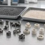
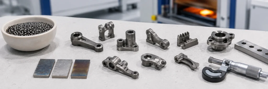
Representative engineering illustration: The feedstock, tooling, and components illustrate engineering relationships and do not imply proprietary XTMIM feedstock or in-house micro-insert manufacturing.
Micro MIM Tooling: Inserts, Cores, Gates, Vents, and Mold Accuracy
A Micro MIM feature cannot be produced unless its inverse geometry can first be manufactured and maintained in the mold. The first tooling question is whether the selected toolmaker can produce the feature with enough accuracy, surface control, strength, alignment, and life for the intended production volume.
Can the Microfeature Be Machined into the Mold?
The review should identify the manufacturing method for the mold insert, minimum internal radius, tool or electrode access, feature depth, surface finish, edge quality, insert alignment, expected wear, and replacement strategy. The final part requirement must also include shrinkage compensation because the mold feature is not normally the same size as the final sintered feature.
Micro Cores and Slender Inserts
Small bores and channels may require slender core pins or inserts. Their supported length, diameter, stiffness, alignment, thermal movement, wear, fracture risk, replaceability, and effect on release should be reviewed together. A core may be manufacturable but still unsuitable for a stable high-cycle mold.
Gate and Vent Design
Gate location controls how the feedstock enters and travels through the cavity. The review should confirm which microfeature fills last, whether the gate produces excessive local shear, whether gate removal can damage the part, whether the gate mark is acceptable, where trapped air can escape, and whether the vent can create flash. A very small gate is not automatically better.
Parting Lines, Flash, and Tool Wear
A parting-line step or small flash height that is minor on a conventional component may consume a significant percentage of a microfeature. The plan should define parting-line location, functional surfaces that must avoid it, allowable flash, insert alignment, wear inspection, maintenance intervals, and replacement criteria.
Tooling Review with the Selected Toolmaker
XTMIM’s mold manufacturing is supported by selected external toolmakers, with internal participation in DFM, trial review, mold correction, and maintenance. For a Micro MIM project, the selected toolmaker should confirm how each critical feature will be manufactured, measured, aligned, replaced, and maintained before mold release.
Evidence Required Before Tooling Release
| Tooling Question | Evidence Required | Hold Condition |
|---|---|---|
| How will the inverse microfeature be manufactured? | The selected tooling method, achievable radius, feature depth, surface condition, and insert-inspection route are identified. | The drawing requires geometry that the toolmaker cannot manufacture or verify. |
| Can a slender core remain stable? | Supported length, alignment method, stiffness, replacement route, and withdrawal direction are reviewed. | Core deflection, breakage, alignment, or replacement risk remains open. |
| Can the cavity fill and vent? | Gate position, last-to-fill feature, trapped-air location, vent route, and gate-removal method are agreed. | The final microfeature or trapped-air region has no credible flow or venting route. |
| Can parting-line and flash effects be accepted? | Parting-line location and allowable flash are tied to functional and inspection requirements. | A critical edge, bore, tooth, or datum is crossed without an acceptance method. |
| Can the tool remain controllable through production? | Wear-sensitive features, insert alignment, maintenance checks, and replacement criteria are defined. | The project relies only on first-shot geometry with no wear or maintenance strategy. |
Filling Limits in Micro MIM Cavities
A finished mold does not prove that the feedstock can fill the geometry. Micro MIM filling must deliver a stable powder-binder mixture to the end of each critical flow path before the material freezes, traps air, or separates.
Flow Length and Early Freeze-Off
Thin sections lose heat quickly. When a microfeature is located far from the gate, the feedstock may experience temperature and pressure loss before it reaches the end of the cavity. Review the actual path through thick-to-thin transitions, narrow ribs, small slots, turns, flow splits, core-pin regions, and final vent locations.
Local Short Shots and Incomplete Replication
A part can have a complete outer shape while failing locally. Typical signs include an incomplete slot end, rounded or missing tooth root, partially formed pillar, weak thin edge, incomplete texture, or a local void around a core. Trial inspection should focus on the smallest functional features, not only the general part outline.
Air Traps, Weld Lines, and Separation
When feedstock flows around a core pin, two flow fronts may meet behind it and create a weld-line region. Elsewhere, the flow may push air into a blind end. High shear at small gates and abrupt transitions may also alter local powder-binder distribution. Potential consequences include inconsistent weight, density variation, different shrinkage, warpage, surface defects, and inconsistent dimensions.
What Trial Parts Must Prove
T1, T2, and T3 reviews should check complete feature replication, consistency among cavities, consecutive-cycle stability, part weight, flash, gate condition, weld lines, Green Part cracks, ejection damage, final dimensions after sintering, and inspection repeatability. For the general molding stage and Green Part quality controls, see the main MIM injection molding page.
Trial Evidence Required Before Progression
| Trial Question | Evidence to Review | Decision if Unresolved |
|---|---|---|
| Is each critical microfeature completely replicated? | Feature-level visual or dimensional review at the slot end, tooth root, bore region, thin edge, or pillar top. | Adjust gate, vent, process window, tooling detail, or feature geometry before progression. |
| Are cavities and consecutive cycles consistent? | Part weight, feature appearance, flash, gate condition, and selected critical dimensions are compared by cavity and cycle. | Do not treat one acceptable sample as evidence of a stable process. |
| Does the Green Part release without damage? | Core-withdrawal marks, cracks, edge damage, ejection marks, bending, and transfer stability are reviewed. | Revise release surfaces, draft, ejection, cooling, handling, or the feature itself. |
| Does the feature remain acceptable after sintering? | The same critical dimensions and profiles are checked after debinding and sintering, not only in the Green Part. | Apply feature-specific compensation, support changes, secondary operations, or design revision. |
| Can the result be measured repeatedly? | The fixture, datum, method, repeatability, and reporting route are demonstrated on trial parts. | Place tooling approval on hold until the inspection route is practical. |
Demolding and Green-Part Handling Limits
After molding, the component is still a Green Part. It contains powder held together by binder and has not developed final metal strength. A completely filled microfeature can still be damaged during mold opening, core withdrawal, ejection, gripping, runner separation, orientation, or tray loading.
Why Micro Green Parts Are Vulnerable
As a feature becomes thinner, its load-bearing cross-section decreases. Friction against a mold surface or core may remain significant relative to the local Green Part strength. Fine teeth, thin edges, narrow bridges, tall ribs, pillars, and thin walls around bores are typical high-risk areas.
Draft Angle and Release Direction
Deep textures, narrow slots, and long cores can increase release friction. The drawing should identify the draw direction, draft on deep surfaces, undercuts, shutoffs, side actions, core withdrawal, surfaces that cannot accept draft, and surfaces that can be modified. Zero draft should not be accepted automatically because the component is small.
Ejection and Load-Bearing Areas
A stable part requires an area that can receive ejection force without damaging a functional feature. Confirm ejector location and size, allowable ejector marks, local support, bending risk, whether the part remains on the intended mold half, and whether automatic pickup is possible.
Core Withdrawal and Transfer
A Green Part can shrink or grip around a core after cooling. Removing the core may create bore-edge cracks, sidewall drag, local stretching, part distortion, core bending, or core breakage. After ejection, the part still needs a repeatable path through runner separation, orientation, tray placement, and transfer to debinding.
Engineering takeaway: Complete filling is only the first success condition. A micro part that cannot be released and handled repeatedly without loading its critical microfeatures is not production-ready.

Representative engineering illustration: The Green Parts and mold setup are generic engineering examples and do not document an actual production trial.
Debinding Limits for Micro MIM Parts
Debinding removes the binder while retaining enough structure for the powder compact to survive until sintering. A Micro MIM part may contain very thin and relatively thick sections at the same time. The thin region may release binder quickly, while the thicker region controls the overall debinding route.
Binder Removal Path and Section Distribution
Review maximum section thickness, thin-to-thick transitions, enclosed regions, blind features, binder-removal path, heating rate, and support condition. The fact that the complete part is small does not mean binder removal is automatically uniform.
Loss of Structural Support
As binder is removed, the component becomes a fragile powder skeleton supported by the remaining backbone binder and contact surfaces. Unsupported walls, tall ribs, long thin bridges, pillars, fine teeth, and asymmetric arms may become vulnerable even if they survived demolding.
Placement, Contact, and Validation
Tray placement must protect the critical geometry. Confirm which surface contacts the tray, whether the part can roll or tilt, whether parts can touch, whether a microfeature carries the part weight, whether contact marks are acceptable, and how the Brown Part will be transferred to sintering.
Possible defects include microcracks, local collapse, surface contamination, binder residue, feature chipping, warpage, and part-to-part sticking. Some defects may remain difficult to see before sintering but become more visible after densification.
Debinding Risk-Control Matrix
| Observed Risk | Likely Cause | Handling or Prevention |
|---|---|---|
| Microcracks that become clearer after sintering | Uneven binder removal, abrupt section transition, handling stress, or inadequate support. | Review section distribution, debinding route, heating conditions, support, and transfer method before changing the final tolerance. |
| Local collapse or leaning feature | A thin wall, tooth, bridge, rib, or pillar loses structural support as binder is removed. | Change orientation, add a stable contact region, use an appropriate setter, or revise unsupported geometry. |
| Contact mark, sticking, or feature damage | The critical surface carries part weight, touches another part, or contacts an unsuitable tray region. | Define part spacing, contact surface, tray material, and transfer direction before production release. |
| Brown Part damage during transfer | The handling method relies on a fragile feature or the part lacks a stable pickup and placement surface. | Design a supported pickup route and confirm that automatic or manual handling is repeatable. |
For the general binder-removal sequence, Brown Part condition, and preparation for sintering, see the full MIM debinding process page.
Sintering Shrinkage and Microfeature Distortion
Sintering densifies the debound powder structure and produces the final metal part. It also causes substantial dimensional change. On a conventional component, a small absolute movement may remain inside a broad tolerance. On a microfeature, the same movement may consume much of the allowable variation.
Why Small Absolute Movement Becomes Significant
The project team should distinguish overall external shrinkage, bore shrinkage, slot opening, tooth thickness, wall thickness, center distance, profile, and feature position. A single global mold scale is a starting point, not proof that every microfeature will reach its target.
Feature Rounding and Shape Loss
During densification, fine edges and small unsupported structures may change shape. Possible results include rounded tooth tips, softened internal corners, reduced texture depth, narrowed or enlarged openings, pillar tilt, thin-edge recession, and local warpage. The engineering question is not whether the feature remains visible but whether it still performs its required function.
| Feature | Potential Change | Functional Risk |
|---|---|---|
| Micro bore | Diameter, roundness, or position change | Fit, flow, concentricity, or assembly failure |
| Narrow slot | Width change, sidewall movement, or partial closure | Insertion or movement restriction |
| Fine tooth | Thickness, pitch, tip, or root change | Poor engagement or running behavior |
| Thin wall | Bowing, waviness, or local thickness change | Weakness or assembly interference |
| Micro pillar | Leaning, bending, or top rounding | Contact or positioning failure |
| Fine edge | Edge recession or rounding | Loss of sealing, contact, or visual definition |
Sintering Support and Orientation
Confirm gravity direction, stable contact surface, required setter, possible contact marks, part spacing, movement during furnace loading, transfer from debinding, and whether support interferes with inspection or finishing. A part with no stable support surface may require a custom setter or a design modification.
Feature-Specific Shrinkage Compensation
Feature-specific compensation uses trial and measurement data to adjust selected mold dimensions instead of changing the complete mold uniformly. It may be needed when a bore and external diameter shrink differently, a slot moves asymmetrically, tooth profile changes independently of the hub, or a thin wall responds differently from a thick base. The broader mold-scaling, trial-correction, and dimensional feedback loop is covered in MIM shrinkage compensation.
Process-chain evidence: The published Micro PIM review literature treats dimensional change as the result of connected molding, demolding, debinding, and sintering effects. For project decisions, compensation should therefore come from feature-level trial and measurement data rather than a research result or one global scale factor being copied into a new mold. See the review source.
When Secondary Operations Should Be Retained
Machining, grinding, sizing, or another finishing operation may be the more stable decision for a precision bore, locating datum, bearing surface, sealing surface, critical center distance, concentric relationship, or surface finish. Micro MIM should create value through complex near-net-shape geometry; it should not be forced to hold every critical dimension in the as-sintered condition.
For the broader densification, atmosphere, shrinkage, and distortion-control process, see the main MIM sintering page. For general tolerance allocation and post-sintering strategy, review high-precision MIM parts.

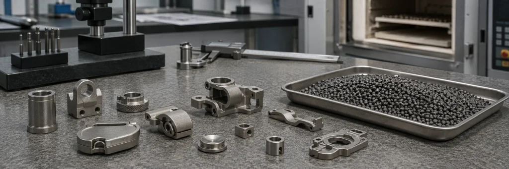
Representative engineering illustration: The staged components illustrate possible process changes and are not measured customer samples or a documented production batch.
Inspection Limits for Micro MIM Features
Micro MIM capability cannot be defined only by molding and sintering. The final feature must also be measurable. A production tolerance should not be assigned until the measurand, datum setup, fixture, method, access, resolution, repeatability, uncertainty, sampling plan, and acceptance rule have been defined.
A Feature Is Not Controlled Until It Is Measurable
There is a practical difference between seeing a feature, measuring it once, measuring it repeatably, measuring it at production speed, and making a traceable acceptance decision. A microscope image can show that a tooth or slot exists, but it does not automatically provide a valid size, position, or profile result.
Inspection Methods by Feature Type
| Feature | Possible Method | Main Limitation |
|---|---|---|
| External profile | Calibrated vision or optical microscopy | Edge detection, lighting, focus, and orientation |
| Narrow slot | Optical profile or section measurement | Hidden depth and line-of-sight restrictions |
| Small through-hole | Optical measurement, small probe, or functional gauge | Access, depth, and edge condition |
| Deep micro bore | Micro-probe CMM, CT, sectioning, or functional validation | Resolution, uncertainty, cost, and cycle time |
| Micro tooth | Optical profile, gear measurement, or functional mesh test | Outside diameter alone does not verify profile |
| Thin wall | Optical, fixture-based, or section measurement | Clamping can deform the component |
| Hidden internal feature | CT, destructive sectioning, or functional test | Throughput and resolution |
| Surface texture | Profilometry, microscopy, or SEM for development | Development methods may not suit routine production |
Datum Strategy and Fixturing
A reliable fixture should establish the intended drawing datums, avoid loading a thin wall, orient the part repeatedly, leave the target feature accessible, prevent rotation or tipping, and support an acceptable inspection cycle time. A datum note is useful only when the datum can be physically contacted, imaged, or functionally established.
Resolution, Accuracy, Repeatability, and Uncertainty
Resolution is the smallest displayed or detectable increment. Repeatability describes variation under repeated conditions. Accuracy concerns closeness to the intended value. Measurement uncertainty describes the range associated with the result for the specific task. A machine may display small increments while the actual task remains uncertain because of probing force, fixture variation, edge detection, temperature, calibration, surface condition, or orientation.
Metrology evidence: NIST describes specialized fiber-probe CMM systems for dimensional and form measurement of microfeatures and small holes, showing why probe access and probing force are part of the measurement problem. NIST also explains that CMM calibration information must be combined with measurement-specific factors to produce a task-specific uncertainty statement. Microfeature probing reference · Task-specific uncertainty reference.
Development Inspection vs Production Inspection
Development inspection can use CT, SEM, destructive sectioning, detailed optical scanning, or high-density laboratory measurement. Production inspection must also consider cycle time, fixture loading, operator influence, automation, sampling frequency, cost, and reporting. A method used to confirm a prototype is not automatically suitable for every production lot.
Inspection Method Release Checklist
Measurand and Datum
The characteristic, datum sequence, evaluation rule, and functional reason are defined on the drawing or inspection plan.
Access and Fixturing
The probe or optical path can reach the feature, and the fixture does not bend, hide, or damage the component.
Capability and Uncertainty
Resolution, repeatability, calibration, environmental effects, and task-specific uncertainty are suitable for the acceptance decision.
Production Execution
Sampling, cycle time, operator method, data recording, and escalation rules are practical for the intended production volume.
For XTMIM’s general equipment and project-level inspection planning, review the Inspection & Testing capability page.
Engineering takeaway: An unmeasurable tolerance is not a controlled production requirement, even when a trial part appears acceptable.

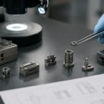
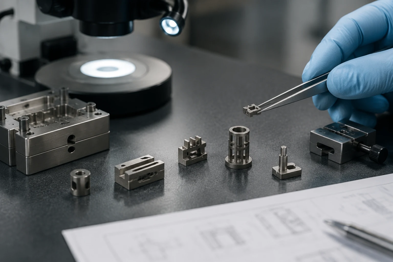
Representative engineering illustration: The measurement setup illustrates inspection planning and does not represent a certified report, customer approval, or guaranteed measurement capability.
Micro MIM Tooling Hold Gates Before Mold Release
The final decision is not simply whether Micro MIM can make small parts. The decision is whether this specific drawing has enough technical evidence to justify formal tooling.
Required Drawing and Project Inputs
| Input | Required Information |
|---|---|
| 3D CAD | Complete geometry and feature relationships |
| 2D drawing | Dimensions, tolerances, datums, and surface requirements |
| Material | Alloy grade or required property direction |
| Critical features | Smallest holes, slots, walls, teeth, ribs, and positions |
| Functional requirement | Fit, motion, sealing, contact, load, or flow function |
| Annual volume | Expected annual demand and batch size |
| Secondary operations | Permitted machining, grinding, sizing, or finishing |
| Inspection requirement | Required methods, reports, sampling, and acceptance |
| Validation requirement | Sample, material, dimensional, and functional approvals |
Eight Tooling Hold Gates
1. Micro-Scale Definition Is Unclear
The team has not identified whether the main risk is complete-part handling, a local microfeature, or a micro-scale dimensional relationship.
2. Critical Feature Limits Are Incomplete
The drawing does not clearly define minimum bore, slot width and depth, wall thickness, tooth profile, aspect ratio, edge radius, or functional tolerance.
3. Feedstock Suitability Is Unconfirmed
The selected commercial feedstock has not been reviewed against alloy, critical feature, flow path, Green Part strength, debinding, and sintering.
4. Tooling Method Is Unconfirmed
The project lacks an agreed method for insert manufacture, slender cores, gate, vent, parting line, ejection, and maintenance.
5. Filling and Demolding Risks Are Open
The team has not shown how the feature will fill, vent, release, eject, and transfer without damage.
6. Debinding and Sintering Support Is Undefined
No stable orientation, tray contact, setter, or distortion-control plan has been agreed.
7. Inspection Is Not Validated
The project lacks a defined measurand, datum, fixture, method, uncertainty, and sampling plan.
8. Unrealistic Requirements Remain
Examples include deep blind micro bores without a core or inspection strategy, zero draft on deep structures, mathematically sharp internal corners, or hidden features requiring complete inspection without a viable method.
Tooling Decision Matrix
| Decision | Conditions | Next Step |
|---|---|---|
| Ready for Tooling | Critical geometry, process, support, and inspection routes are defined. | Release formal tool design. |
| Conditional Release | Specific risks require T1 evidence. | Release with written trial conditions. |
| Design Revision Required | Geometry can be improved before tooling. | Revise feature, radius, draft, support, or tolerance. |
| Secondary Operation Required | A local requirement is not stable as-sintered. | Add machining, grinding, sizing, or finishing. |
| Process Reconsideration | The complete process chain remains impractical. | Review machining, stamping, etching, additive, or an assembly route. |
| Tooling Hold | Critical information or inspection evidence is missing. | Do not release formal tooling. |
Representative Engineering Scenario: Small Bore, Narrow Slot, and Position-Controlled Feature
A compact stainless-steel component contains a small through-bore, a narrow blind slot, a thin sidewall, and a positional requirement between the bore and an external datum. The initial request is to produce all features in the as-sintered condition.
- Confirm whether an available commercial feedstock is suitable for the bore, slot, and wall.
- Review the bore core for stiffness, alignment, wear, and withdrawal.
- Check whether the slot end can vent and fill completely.
- Confirm that the thin wall has a stable ejection and handling path.
- Select a debinding and sintering orientation that does not load the thin wall.
- Review bore movement, slot opening, and feature position after sintering.
- Define how the bore, slot, and positional relationship will be measured.
- Decide whether the bore or datum requires a local secondary operation.
The outcome may be to release the mold, revise the slot or wall, increase an allowable radius, adjust the tolerance split, retain bore finishing, or place the project on hold until inspection is confirmed.
Representative Engineering Scenario: This example illustrates a typical Micro MIM review sequence. It is not a customer case, production record, or guaranteed dimensional capability.
Final Engineering Decision
Micro MIM creates the most value when a stable production design combines useful micro-scale geometry with suitable feedstock, manufacturable tooling, complete cavity filling, controlled Green Part release, protected debinding, stable sintering support, and a validated measurement method. For a broader solution-level review of project fit, production volume, and sourcing inputs, see miniaturized metal components.
Where one condition cannot be controlled, the correct decision may be to modify the feature, increase a radius, add draft, change the gate or support direction, revise the tolerance, retain a local secondary operation, or use another process.
Frequently Asked Questions About Micro MIM
What is Micro MIM?
Micro MIM is a scale-sensitive form of metal injection molding used for complete micro parts, components containing microfeatures, or parts requiring micro-scale dimensional relationships. The process still uses powder-binder feedstock, injection molding, debinding, and sintering, but feature replication, Green Part release, distortion, and inspection become more demanding as the scale decreases.
Is there a fixed size limit for Micro MIM parts?
No single external dimension defines every Micro MIM project. Overall size, feature width, depth, aspect ratio, powder size, tooling method, tolerance, and inspection access must be reviewed together. A larger part containing a difficult microfeature may require a more demanding review than a smaller part with simple geometry.
What is the smallest feature Micro MIM can produce?
There is no universal minimum feature that applies to all materials, powders, molds, and geometries. Published experimental results are achieved under specific conditions and should not be treated as automatic production guarantees. The smallest critical feature must be reviewed against feedstock, tooling, filling, demolding, sintering, and inspection requirements.
Can Micro MIM form very small holes and slots?
Small holes and slots can be evaluated, but feasibility depends on more than nominal width or diameter. Core stiffness, feature depth, venting, flow path, draft, Green Part release, sintering movement, and measurement access can determine whether the feature is suitable for direct molding or should retain a secondary operation.
How are Micro MIM features inspected?
Possible methods include calibrated optical measurement, microscopy, small-probe CMM systems, CT, dedicated gauges, destructive sectioning, or functional validation. The correct method depends on the feature, datum, tolerance, access, measurement uncertainty, production volume, and inspection cycle time.
Does Micro MIM eliminate secondary machining?
Not always. MIM can form complex near-net-shape geometry, but precision bores, datums, sealing surfaces, concentric relationships, or very tight local tolerances may still require machining, grinding, sizing, or another secondary operation.
Technical References
The following sources support the engineering background on Micro PIM classification, particle-size effects, process-chain dimensional behavior, microfeature metrology, and measurement uncertainty. Key sources are also linked beside the claims they support. Research results are context-specific and are not presented as XTMIM production guarantees.
- Attia and Alcock: A review of micro-powder injection moulding as a microfabrication technique — Review of Micro PIM capabilities, classifications, process stages, and limitations.
- Okubo, Tanaka, and Ito: Effects of particle size and distribution on dimensional accuracy in micro metal injection molding — Research on the relationship between powder properties and micro-part dimensional behavior.
- NIST: Micro-feature dimensional and form measurements with a fiber probe on a CMM — Background on specialized probing for microfeatures and small holes.
- NIST: Traceability, calibration, and measurement uncertainty for coordinate measuring machines — Background on task-specific measurement uncertainty and traceability.
Submit Your Micro MIM Drawing for Review
Share the 3D model, 2D drawing, material requirement, annual volume, smallest critical features, tolerance priorities, allowed secondary operations, and inspection requirements. XTMIM can review whether the proposed geometry has a practical route through feedstock selection, mold construction, cavity filling, Green Part release, debinding, sintering, and final inspection before the formal tooling and quotation scope are confirmed.