Metal injection molding for small complex parts creates the most value when a stable production design combines feature-dense three-dimensional geometry, a suitable engineering metal, repeat annual demand, and a realistic opportunity to replace recurring CNC operations with near-net-shape production. This guide uses a representative CNC-to-MIM engineering example to show how part size, weight, alloy, annual …
Metal injection molding for small complex parts creates the most value when a stable production design combines feature-dense three-dimensional geometry, a suitable engineering metal, repeat annual demand, and a realistic opportunity to replace recurring CNC operations with near-net-shape production. This guide uses a representative CNC-to-MIM engineering example to show how part size, weight, alloy, annual volume, tolerances, sintering shrinkage, tooling revisions, secondary machining and process capability should be reviewed before tooling.
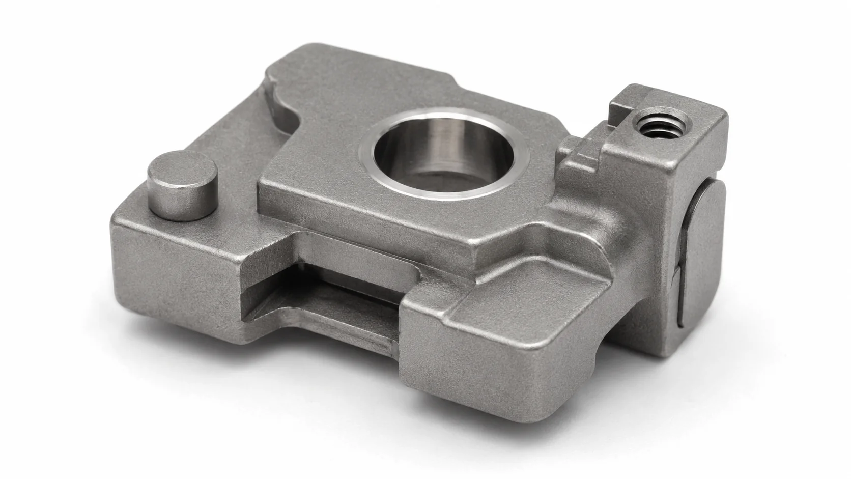
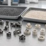
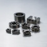
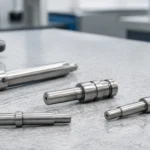
The geometry includes a central functional bore, side slot, bosses, steps, thin sections and multi-directional features. These are the types of features that can create repeated machining cost when annual demand becomes stable.
Quick Answer: When Should a Small Complex Metal Part Be Reviewed for MIM?
Feature-dense geometry
Metal injection molding should be reviewed when a small metal part has side features, compact slots, bosses, steps, thin sections, undercuts or multiple functional planes that make CNC access, fixturing and deburring repetitive.
Stable repeat demand
MIM becomes more practical when the design is stable and annual demand can justify tooling, sampling, shrinkage validation and inspection. Volume should be evaluated together with geometry complexity and current manufacturing cost.
Selective finishing only
A strong small complex MIM part forms most geometry near net shape and keeps secondary machining only for selected CTQ bores, threads, datums, sealing surfaces or precision fits.
Decision rule:
MIM is not selected only because a part is small. It becomes attractive when molded complexity can remove enough recurring CNC machining, fixturing, deburring or assembly work to justify tooling and process validation. If the part is still changing, has very low demand, or requires precision machining on most surfaces, CNC or another process may remain the better first choice. For a dedicated process comparison, review MIM vs CNC machining for small complex parts.
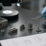
Representative CNC-to-MIM Engineering Example
Evidence status:
The numerical case and graphics below are a representative engineering example created to demonstrate the information a publishable MIM case study should contain. They must not be presented as an actual customer case, actual released inspection report or named engineer review unless XTMIM verifies the project records, customer authorization and reviewer identity.

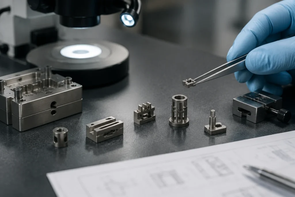
A useful case study connects the part drawing with the original process, MIM route, tooling corrections, dimensional capability and production result. A product image alone is not sufficient evidence.
Original route
CNC machining
- Six machining and handling operations
- Approximately 9.5 minutes total cycle time per part
- Repeated fixturing for multi-directional features
- Deburring and inspection repeated on every component
Revised route
MIM plus selective finishing
- Main body, side slot, steps and bosses formed near net shape
- Critical bore reamed after sintering
- M3 feature tapped after sintering
- Two secondary operations retained instead of machining the complete body
Part Dimensions, Material, Volume and Production Data
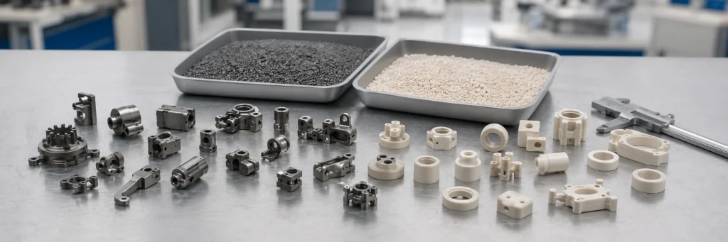
A credible small complex MIM case should state the actual engineering inputs rather than relying on general claims such as “high volume” or “tight tolerance.” The table below shows the level of detail that should be documented.
| Project item | Representative case value | Engineering significance |
|---|---|---|
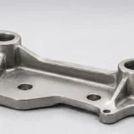
| Overall part size | 28.4 × 16.8 × 8.2 mm | Compact enough for a small-part MIM review, while still containing several three-dimensional features. |
| Finished part weight | 14.6 g | Weight supports efficient multi-cavity or repeat production review, subject to tooling and feedstock economics. |
| Material grade | MIM 17-4 PH stainless steel | Selected for a strength-driven stainless application; final material condition and heat treatment must be specified. |
| Estimated annual demand | 180,000 parts/year | Provides a meaningful volume base for comparing recurring CNC cost with tooling and validation investment. |
| Original CNC operations | 6 operations | Indicates repeated setup, tool access, deburring and inspection burden. |
| Original CNC cycle time | Approximately 9.5 min/part | The recurring cycle is a major cost driver at repeat production volume. |
| MIM secondary operations | 2 operations | Ream the Ø3.00 mm critical bore and tap the M3 threaded feature. |
| General as-sintered tolerance | ±0.30% | Used for non-critical features in this example; tolerance must be confirmed by feature, datum and process capability. |
| Critical bore tolerance | Ø3.00 +0.02 / 0.00 mm | Held by post-sinter machining rather than applying the same tight requirement to every molded dimension. |
| Average linear sintering shrinkage | 15.8% | Used as a tooling-compensation input; local movement and directional variation still require trial validation. |
| First-pass yield | 96.8% | Represents a production-quality indicator after the revised tooling and support plan. |
| Critical bore capability | Cpk 1.52 | Shows the type of capability evidence needed for a CTQ dimension after the measurement system and sampling plan are defined. |
| Material density | >97% theoretical | Should be tied to the agreed material specification, sampling method and inspection record. |
For material-specific review, see the dedicated MIM 17-4 PH stainless steel guide. Material grade, heat-treatment condition, density, hardness, corrosion environment and dimensional stage should be defined together rather than inferred from the alloy name alone.
Tooling Modification Before and After Comparison
A stronger case study explains what changed during tooling development. It should not jump directly from “tool built” to “production passed.” In this example, the first tooling concept created both dimensional and cosmetic risk.
Tooling Rev A
Side gate and unstable support
- Side gate left a visible witness mark near a sensitive surface.
- Flow and local packing increased dimensional variation around the functional region.
- The sintering orientation provided insufficient support beneath an asymmetric span.
- Flatness and bore-location variation required additional review.
Tooling Rev B
Underside gate and dedicated support pad
- Gate moved to an underside non-cosmetic zone.
- A support pad and revised sintering orientation improved stability.
- Wall transitions and local radii were balanced to reduce distortion sensitivity.
- Inspection focused on Datum A, bore size, bore position, slot width and flatness.
Why this matters:
Tooling correction is useful SEO and engineering evidence only when the article explains the defect mechanism, the design or process change, and the measured result. A before-and-after image without the cause-and-correction logic adds little technical value.
DFM Review: Which Features Stay As-Sintered and Which Need Machining?

The DFM decision separates molded geometry from post-machined CTQ features and connects gate placement with cosmetic zones, sintering support, wall balance and inspection access.
| Feature | Selected route | Reason for the decision |
|---|---|---|
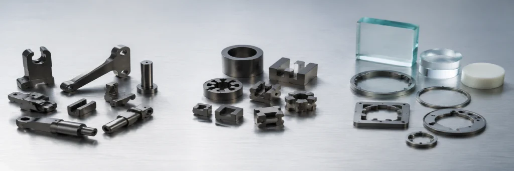
| Main outer profile, steps and bosses | As-sintered MIM | These features contain the repeatable geometric complexity that creates the conversion value. |
| Side slot | Formed in tooling | Avoids repeated slot machining, subject to mold direction, shut-off, flash control and inspection access. |
| Ø3.00 mm functional bore | Molded with machining allowance, then reamed | The unilateral CTQ tolerance and surface requirement justify selective finishing. |
| M3 threaded feature | Molded pilot feature, then tapped | Reduces tooling and thread-quality risk while retaining most body geometry as molded. |
| Bottom support surface / Datum A | Controlled through support and inspection | The datum influences flatness, bore position and CMM alignment. |
| Gate vestige | Underside non-cosmetic zone | Protects visible and functional surfaces while supporting a more stable fill path. |
Feature-level decisions should be checked against the complete MIM design guide, the holes, slots and undercuts guide, sintering support guidance and the drawing-based DFM for MIM review process.
Actual Tolerances, Shrinkage Data and Inspection Evidence
A MIM article should distinguish between general as-sintered capability and critical dimensions that receive dedicated process control or machining. Applying a single tight tolerance to every feature usually adds cost and makes the drawing less realistic.

This generated graphic demonstrates the type of dimensional evidence a real case should publish. It is not a customer-released inspection certificate. Replace it with a masked, traceable report before claiming actual production evidence.
Critical dimensions and inspection methods
| Inspection item | Specification used in the example | Suggested method | Control purpose |
|---|---|---|---|
| Overall length | 28.40 ±0.10 mm | CMM or optical measurement | Confirms global shrinkage and tooling compensation. |
| Overall width | 16.80 ±0.10 mm | CMM or optical measurement | Checks directional shrinkage and part stability. |
| Overall thickness | 8.20 ±0.05 mm | CMM | Tracks support condition and vertical distortion. |
| Critical bore | Ø3.00 +0.02 / 0.00 mm | Air gauge, bore gauge or CMM | Verifies the post-machined CTQ fit. |
| Slot width | 2.40 ±0.05 mm | CMM or functional gauge | Checks an as-sintered molded feature. |
| Hole position | 12.50 ±0.03 mm | CMM from defined datums | Confirms positional stability after sintering and machining. |
| Flatness on Datum A | 0.05 mm maximum | CMM or surface plate method | Validates the revised support strategy. |
| Machined bore finish | Ra 1.6 | Surface roughness tester | Confirms functional surface condition. |
How to publish yield and Cpk responsibly
A value such as 96.8% first-pass yield or Cpk 1.52 is meaningful only when the article also states the inspected feature, sample size, measurement method, revision level and production stage. The example uses 30 measured pieces for the critical bore. A real publication should retain the source report, measurement-system information and drawing revision even when customer-identifying fields are masked.
For deeper dimensional guidance, link readers to MIM as-sintered and critical tolerances, MIM shrinkage compensation and XTMIM’s inspection and testing capability.
Decision Table: Is the Part a Strong MIM Candidate?

The ranges are screening references, not universal limits. A final decision requires drawing, material, tooling, tolerance, sintering and cost review.
Strong candidate
Small feature-dense geometry, stable annual demand, established alloy route, limited CTQ finishing and a clear recurring CNC or assembly cost problem.
Borderline candidate
Moderate volume, uncertain material condition, many shrinkage-sensitive dimensions, unclear datum strategy or several tight surfaces that may need machining.
Weak candidate
Prototype-only demand, unstable design, simple turned or stamped geometry, large block-like shape, or heavy secondary machining across most surfaces.
When MIM Creates Real Value for Small Complex Metal Parts
1. The geometry creates repeated manufacturing cost
MIM becomes relevant when several features are expensive to machine one part at a time: side details, compact slots, thin ribs, bosses, steps, curved transitions, miniature holes, multi-level surfaces or integrated features that would otherwise require several setups.
2. The design is stable enough for tooling
Tooling compensation, gate location, ejection, sintering support and first-article correction depend on a mature geometry. Early prototypes can still be reviewed for future MIM suitability, but mold release should wait until the functional architecture and CTQ dimensions are sufficiently stable.
3. The annual demand can absorb tooling and validation
No universal annual-volume threshold applies to every MIM project. A small high-value component with severe machining burden may justify tooling at a lower volume than a simple inexpensive part. The correct comparison includes tooling, trial correction, process validation, secondary operations, inspection, expected program life and the original recurring unit cost.
4. Most complexity can remain near net shape
The business case is strongest when MIM creates the complete complex body and only selected CTQ features receive post-sinter finishing. A hybrid route can be more realistic than insisting that every functional dimension remain as-sintered.
5. Material performance matches the application
The selected material must fit strength, hardness, corrosion, wear, temperature, magnetic and finishing requirements. The project should also define density, heat-treatment condition, surface state and final inspection stage.
When MIM Is Not the Best First Choice
Stay with CNC or prototype manufacturing when:
- The design is still changing frequently.
- Demand is very low or one-time.
- Most surfaces need direct precision machining.
- The geometry is simple and inexpensive to machine.
- Fast design iteration matters more than production tooling.
Compare another volume process when:
- The part is a simple uniaxial PM shape.
- The component is primarily a flat stamped form.
- The geometry and alloy are better suited to die casting or investment casting.
- The application can use a polymer instead of metal.
- The MIM route would still require extensive finishing and assembly.
Use the MIM process comparison hub when the first decision is whether to compare MIM with CNC machining, powder metallurgy, die casting, investment casting, stamping or metal 3D printing.
Related Engineering Resources
This page should remain the decision-and-case-study entry point. Detailed design, material, process and inspection questions should move to the dedicated pages below rather than being duplicated here.
What to Send for a Small Complex MIM Part Review
| Required input | What it allows the engineering team to review |
|---|---|
| 2D drawing with datums and CTQ dimensions | Tolerance strategy, inspection method, machining allowance and acceptance criteria. |
| 3D CAD file | Mold direction, wall balance, undercuts, side actions, flow path, support and ejection risk. |
| Actual material grade and final condition | Feedstock route, sintering behavior, heat treatment, density, hardness and surface requirements. |
| Finished part weight and envelope size | Basic process fit, tooling concept, handling and production planning. |
| Annual demand and program life | Whether tooling and validation can be justified against recurring process cost. |
| Current process operations and cycle time | Which recurring CNC, deburring, finishing or assembly costs MIM may remove. |
| Functional and cosmetic no-mark zones | Gate, parting line, ejector, support and finishing decisions. |
| Required inspection records | First article, capability, material verification, surface, hardness and production release planning. |
Engineering Review and Evidence Disclosure
Reviewed at article level by: XTMIM Engineering Team
The page has been structured around MIM process suitability, CNC-to-MIM conversion logic, DFM, material direction, tooling revision, shrinkage compensation, tolerance allocation, secondary operations and inspection planning.
Publication requirement: Add a real reviewer’s name, title, biography, portrait and profile URL only after that person has reviewed the final article and authorized publication. The generated “Daniel Chen” reviewer graphic supplied with this project is not included because it must not be presented as a real engineer profile.
FAQ About MIM for Small Complex Parts
What size parts are suitable for metal injection molding?
MIM is commonly evaluated for small, feature-dense metal components, but there is no single universal size limit. Suitability depends on part mass, wall distribution, flow length, material, tooling, handling, debinding, sintering support, dimensional requirements and volume. A drawing-based review is more useful than a size number alone.
What annual volume makes MIM cost-effective?
There is no fixed annual-volume threshold for every part. The crossover depends on tooling cost, current CNC or assembly cost, geometry complexity, program life, material, cavity strategy, yield, secondary operations and inspection requirements. Stable repeat demand is more important than quoting one universal quantity.
Can MIM replace all CNC machining on a complex part?
Not always. A strong conversion often uses MIM for the complex body and retains CNC finishing for selected bores, threads, sealing faces, bearing fits, datums or other CTQ features. The goal is to remove unnecessary recurring machining, not to eliminate machining at any cost.
Is ±0.3% a guaranteed MIM tolerance?
No. A percentage such as ±0.3% is only a general screening reference. Actual capability varies by dimension length, material, geometry, tooling layout, shrinkage direction, support, furnace process, datum structure and inspection method. Every critical feature should be reviewed separately.
Why is sintering shrinkage important in tooling design?
The molded green part is larger than the final metal component because it shrinks during debinding and sintering. Tooling must compensate for expected shrinkage, while trials confirm local and directional behavior. Average shrinkage alone does not guarantee that every feature moves uniformly.
What evidence should a real CNC-to-MIM case study include?
It should include the customer-approved part or a properly anonymized image, dimensions, weight, material grade, annual volume, original process steps and cycle time, MIM secondary operations, CTQ tolerances, shrinkage or tooling-compensation data, tooling revisions, yield or capability results, and a traceable inspection report with confidential details masked.
What information should be submitted for a MIM feasibility review?
Submit the 2D drawing, 3D CAD file, material and final condition, CTQ tolerances, cosmetic zones, surface requirements, annual volume, current manufacturing route, application environment and expected inspection documentation.
Send the Part for a Drawing-Based MIM Review
For a small complex part currently produced by CNC machining, casting, powder metallurgy, stamping or assembly, provide the drawing, CAD file, material, annual demand, current operations, cycle time, CTQ dimensions and surface requirements. XTMIM can review whether the project should remain with the existing process, move toward MIM, or use a hybrid MIM plus machining route.
Submit a Drawing for Review Contact XTMIMTechnical References
General MIM process and design references can help frame an early review, but they do not replace project-specific material, drawing, tooling and inspection validation. Useful industry starting points include the Metal Injection Molding Association process overview, the European Powder Metallurgy Association MIM overview and MPIF standards resources.