MIM Drawing & DFM Questions Quick Answer For industrial mounting, locating and support brackets, a MIM bracket design review should evaluate ribs, bosses, mounting faces, locating holes, datums and sintering orientation as one connected system rather than as separate drawing features. A rib may improve bending stiffness but still create a thick junction or asymmetric …
MIM Drawing & DFM Questions
Quick Answer
For industrial mounting, locating and support brackets, a MIM bracket design review should evaluate ribs, bosses, mounting faces, locating holes, datums and sintering orientation as one connected system rather than as separate drawing features. A rib may improve bending stiffness but still create a thick junction or asymmetric shrinkage path. A boss may support a fastener but concentrate mass, shift a hole axis or complicate inspection. Datums must be based on surfaces and holes that remain stable, accessible and measurable after sintering and any secondary operation.
Large plates, long arms, offset bosses and uneven rib networks can increase bow, twist or positional variation. Before tooling, define the functional load path, critical assembly interfaces, datum structure, acceptable as-sintered dimensions, possible secondary operations and final inspection method. This review helps determine whether the MIM bracket part is suitable as drawn, needs geometry adjustment or requires a planned finishing operation.
Important validation boundary: drawing review can identify risk, define the tooling and support strategy, and establish an inspection plan. Final flatness, position and repeatability still need to be confirmed with trial parts under the agreed production and measurement conditions.
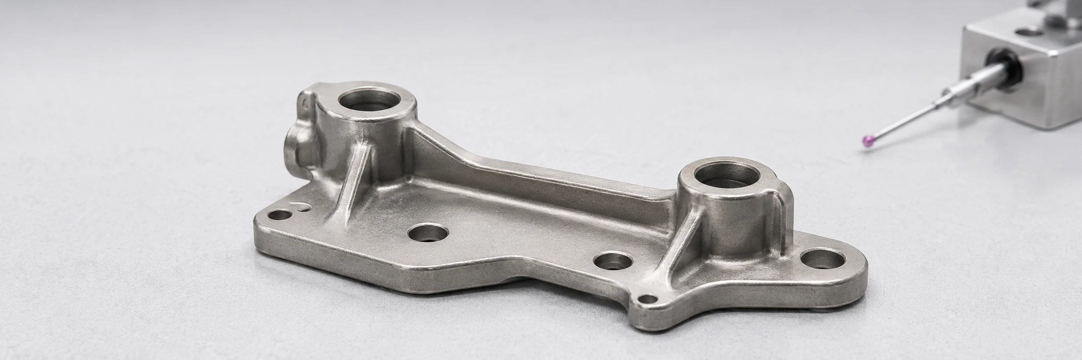
Engineering takeaway: A bracket should be reviewed as one connected geometry system before tooling, not as isolated ribs, bosses and holes.
Five Pre-Tooling Hold Gates for a MIM Bracket
Tooling should not be released while the bracket function, dimensional references or finishing route remain open to interpretation.
These hold gates convert a general DFM discussion into a documented release decision. They help engineering, sourcing and quality teams distinguish a design question that can be resolved from the drawing from a performance question that must remain in the trial-validation plan.
| Hold Gate | Release Criteria | If Unresolved | Evidence Needed |
|---|---|---|---|
| 1. Functional interfaces | Mounting face, load path, fastener direction, locating features and clearance features are identified. | Ribs, bosses and tolerances may be optimized around the wrong function. | 2D drawing, 3D model, mating condition and load description |
| 2. Geometry and local mass | Rib roots, boss cores, wall transitions, long arms and asymmetric heavy sections have a defined disposition. | Tooling may lock in avoidable filling, shrinkage or distortion risk. | Section review, feature map and approved DFM actions |
| 3. Datum and inspection strategy | Primary, secondary and tertiary references match the real assembly and remain measurable after finishing. | Parts may be measured from references that do not predict assembly performance. | Datum scheme, fixture concept and acceptance method |
| 4. Sintering orientation and support | Probable orientation, support contact, protected surfaces and high-risk unsupported regions are reviewed. | Flatness or position issues may appear only after the tool and setter concept are already constrained. | Orientation sketch, support concept and risk register |
| 5. Secondary operations and acceptance | As-sintered features, machining allowance, finishing sequence and final inspection references are agreed. | Quotation, fixture design and final acceptance can be based on different assumptions. | Operation route, inspection plan and critical-feature list |
What Drawing Review Can Decide
- Whether each rib and boss has a justified function
- Where local mass and abrupt transitions should be reduced
- Which surfaces and holes should control the datum chain
- Which geometry requires a support or orientation study
- Where finishing allowance and measurement access are needed
What Trial Parts Must Confirm
- Actual dimensional trend after molding, debinding and sintering
- Flatness, hole position and angular response under the selected support condition
- Whether the planned finishing allowance is sufficient and stable
- Whether the inspection setup gives repeatable, assembly-relevant results
- Whether the agreed acceptance criteria are practical for production
Engineering takeaway: The purpose of a pre-tooling review is not to promise final capability from CAD. It is to remove avoidable uncertainty and convert the remaining uncertainty into a controlled trial and inspection plan.
Start With the Bracket’s Function, Load Path and Mounting Interfaces
A bracket should not be reviewed only as an outer shape. The first task is to identify what the part must support, locate, clamp or connect in the final assembly.
The functional load path determines whether a rib is necessary, where a boss should connect to the main body and which surfaces or holes should become critical inspection features. Without this information, a designer may add material to areas that do not improve the real function while leaving the actual load path unsupported.
Identify the Load Path and Fastening Direction
The review should establish whether the bracket primarily experiences bending, torsion, shear, screw preload or a combination of these conditions. The fastening direction also matters because a boss that supports axial clamp load may need a different surrounding structure from a boss used only for clearance.
This does not require a complete structural-analysis report during the first RFQ review. It does require enough functional information to distinguish necessary reinforcement from decorative geometry.
- Where does the assembly load enter the bracket?
- Which surfaces transfer the load to the mating component?
- Do fasteners create clamp load, shear load or both?
- Do long arms or offset features create a bending moment?
- Which dimensions directly affect assembly position?
Separate Functional Interfaces From Non-Critical Geometry
Not every face, hole or profile needs the same dimensional control. A mounting face may need to seat consistently against another component. A locating hole may control assembly position. A clearance hole may only need sufficient space for a fastener. An outer cosmetic profile may have little effect on function.
Separating these categories allows the project team to focus dimensional control and inspection effort where it matters. It also reduces the risk of applying tight requirements to the entire bracket, which can add tooling complexity, secondary operations, inspection time and cost without improving assembly performance.
Mark Mounting Faces, Locating Holes and Critical Features
The drawing should identify primary mounting or seating faces, locating holes, clearance holes, threaded or tapped features, bearing interfaces, flatness- or position-critical areas and any surface that may later be machined or ground.
| Feature Type | Functional Question | DFM Question | Inspection Question |
|---|---|---|---|
| Mounting face | What surface carries or transfers the assembly load? | Can it remain stable during sintering? | Can it provide a repeatable primary datum? |
| Locating hole | Does it position the assembly? | Is the expected molded and sintered position sufficient? | From which datum is position measured? |
| Clearance hole | Does it only provide fastener access? | Is adequate clearance available after shrinkage? | Is a functional gauge sufficient? |
| Screw boss | Does it carry clamp load or only guide a fastener? | Is local material concentration necessary? | Does the bore require tapping, reaming or final inspection? |
| Rib | Does it reinforce the actual load path? | Does it create a thick junction or unsupported section? | Does it block measurement or fixture access? |
Engineering takeaway: A reliable bracket review begins with function. Geometry should support the load path, assembly interface and inspection logic rather than simply making the CAD model appear stronger.
How to Review Ribs Without Creating New MIM Risks
Ribs can improve stiffness without making an entire bracket wall thicker, but they should not be treated as risk-free reinforcement.
In MIM, ribs affect material flow during injection, green-part handling, local debinding conditions, shrinkage behavior and sintering stability. The important issue is not whether a rib exists. It is whether its position, direction and connection to the main wall create a balanced structure.
Use Ribs to Support the Real Load Path
A rib should connect areas that need load transfer or bending resistance. Adding ribs in unrelated directions may increase material volume and tooling complexity without improving the functional condition.
A common mistake is to use multiple ribs as a general response to uncertainty. More ribs do not automatically produce a more stable MIM bracket. An unnecessary rib can create another thick intersection, another flow restriction and another local shrinkage path.
Review Rib-to-Wall Transitions and Junction Thickness
The nominal rib may appear thin, but the effective section at the rib root can become much thicker where it joins the bracket wall, a boss or another rib. This local material concentration can affect cooling after injection and shrinkage during sintering.
The complete junction should be reviewed rather than evaluating nominal rib thickness alone. For broader guidance on local thick sections, coring and gradual transitions, use the dedicated MIM wall thickness design page.
The Metal Injection Molding Association notes that coring can reduce heavy cross-sections and material use, while ribs and webs can reinforce thin sections and help limit distortion when the geometry remains compatible with tooling.[1]
Check Rib Height, Direction and Unsupported Length
Tall or long ribs may improve stiffness in one direction while becoming flexible or difficult to support in another. Long unsupported features can be vulnerable during green-part handling and may respond to gravity during sintering.
Consider Molding and Measurement Access
A structurally useful rib may still create manufacturing or inspection problems if it blocks a core, creates a difficult filling path or prevents a probe or gauge from reaching a critical surface. Before tooling, review the rib layout together with gate strategy, parting-line direction, core movement, fixture access and inspection contact points.
Escalate the Review When Several Rib Risks Overlap
- A rib terminates directly at a locating hole, precision bore or critical mounting edge.
- Several ribs converge at the same boss or base-wall node.
- A long rib is supported at one end but remains free along most of its length.
- Ribs are concentrated on one side of a thin plate and create an unbalanced section.
- The rib blocks a probe, gauge, machining tool or setter contact that the process plan requires.
Engineering takeaway: A rib can reduce bending without improving dimensional stability if it creates asymmetric mass, a heavy junction or an unsupported shrinkage path.
How to Review Bosses, Screw Features and Local Thick Sections
Bosses support fasteners, locating pins, threads, pivots or bearing interfaces, but they are also a common source of local material concentration.
Define the Boss Function
For each boss, confirm whether it provides fastener clearance, screw clamp support, thread engagement, assembly location, pivot alignment, spacing or a reference for later machining and inspection. The function affects the required diameter, wall structure, core strategy, bore condition and final tolerance.
Reduce Unnecessary Solid Mass
A solid boss may be easy to model, but the full material volume may not be functionally necessary. Where geometry and tooling allow, coring or relieving the boss can reduce local mass concentration and improve the transition into the main bracket body.
The objective is not to hollow every boss. It is to remove material that does not contribute to load transfer, thread engagement or assembly support while retaining practical core-pin strength, wall balance and finishing allowance.
Coring direction, core-pin access and the surrounding wall transition should therefore be reviewed together rather than treating the boss bore as an isolated feature.[1]
Connect Bosses Without Abrupt Section Changes
A boss standing on a thin plate creates a strong local change in section. Adding a rib between the boss and a sidewall may improve load transfer, but the resulting three-way intersection can also become a heavy node. Boss coring, rib direction, wall transition and mass balance should be reviewed together.
Decide Whether Holes and Threads Should Be Molded or Finished
A molded hole may be sufficient for a fastener-clearance function. A locating bore, precision pivot or controlled thread may require a secondary operation depending on the assembly requirement. Possible routes include an as-sintered clearance hole, molded pilot followed by tapping, molded allowance followed by reaming or post-sintering machining.
Specify Boss Decisions on the Drawing Review Record
- Boss function: clearance, clamp support, thread, location, pivot or bearing
- Required bore route: as-sintered, pilot, tapped, reamed or machined
- Minimum functional bearing area and thread-engagement requirement
- Approved coring or relief concept and surrounding wall condition
- Machining allowance, first-operation datum and final inspection datum
- Any surface or positional requirement that depends on the boss axis
| Boss Requirement | Main Risk | Review Before Tooling | Possible Route |
|---|---|---|---|
| Clearance hole | Diameter and position after shrinkage | Assembly clearance and datum relationship | As-sintered or secondary sizing |
| Locating hole | Positional repeatability | Stable datum system and inspection setup | Reaming or machining may be reviewed |
| Threaded boss | Local mass and thread condition | Core diameter, thread engagement and wall balance | Molded pilot plus tapping is one possible route |
| Bearing or pivot boss | Axis alignment and wear | Axis relationship, material and surface requirement | Machining or finishing may be required |
| Clamp-load boss | Seating and local compression | Bearing area, boss support and wall transition | Geometry review plus possible face finishing |
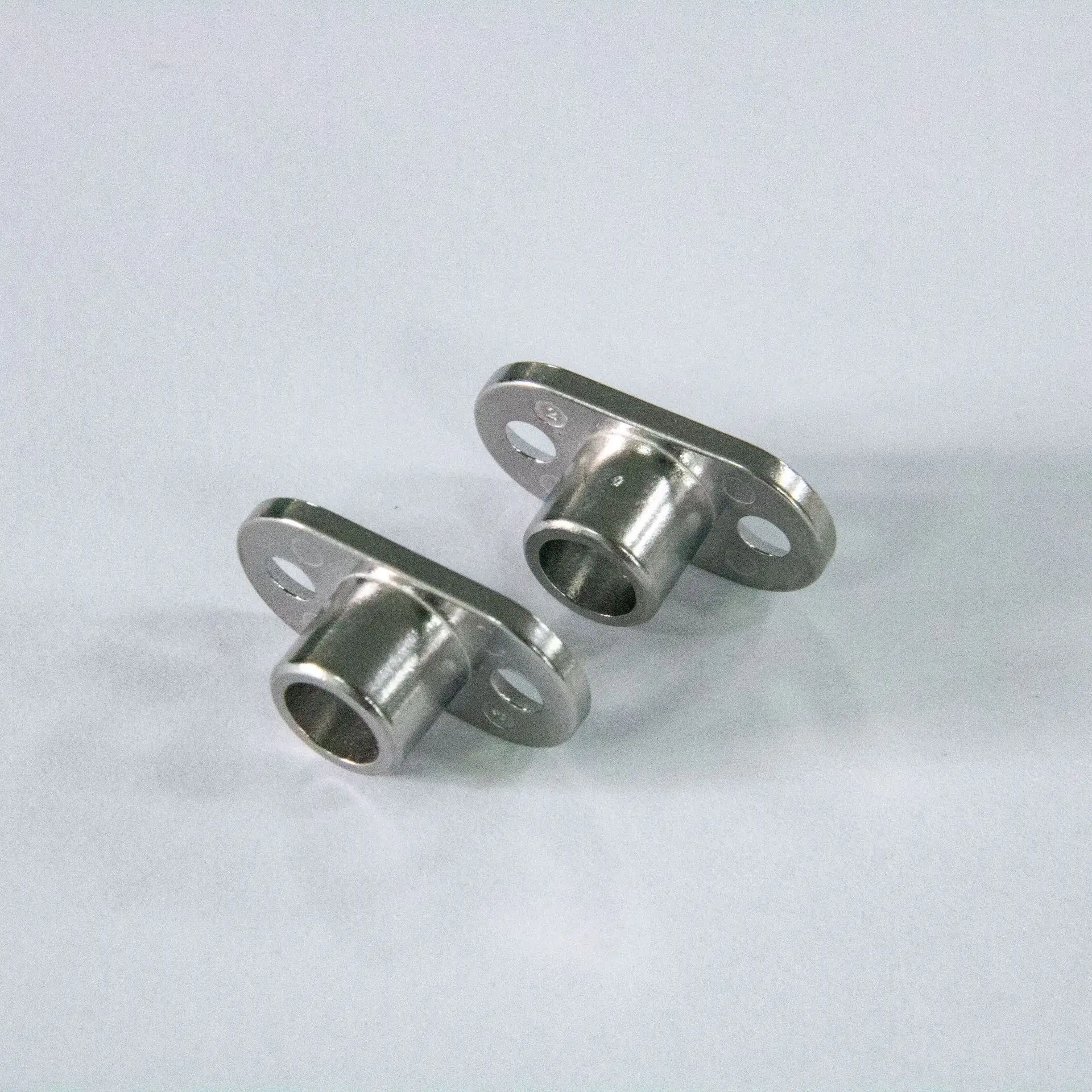
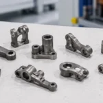
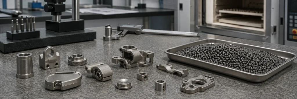
Engineering takeaway: Real parts make the boss function and local mass concentration easier to assess before deciding whether coring, wall transition or secondary finishing is required.
Engineering takeaway: Boss design should be driven by fastening, location or bearing function. Solid volume, bore condition and secondary operations should be justified by the assembly requirement.
Build the Datum Strategy Around Stable and Measurable Features
A datum system should represent how the bracket is assembled and inspected. It should not be selected only because a surface is convenient to mark on the drawing.
Choose a Stable Primary Datum Surface
The primary datum usually needs enough contact area to constrain the bracket in a repeatable way. A small rib edge, narrow boss rim, flexible arm or irregular surface may not provide stable seating.
A large face is not automatically a good datum. If the face is vulnerable to bow or twist, its stability must be evaluated before it is used to control multiple dimensions.
Use Secondary and Tertiary Datums to Control Rotation and Position
A locating hole may be a suitable secondary datum when it controls position in the mating system. A clearance hole should not be treated as a locating feature unless the assembly function supports that decision.
Align Drawing Datums With Assembly and Inspection
A datum structure that does not match the final assembly can create a part that passes inspection but does not assemble consistently. Engineering, manufacturing and quality teams should use the same functional references wherever practical.
Rebuild the Datum Chain After Secondary Operations
When a mounting face is milled or ground, or when a locating bore is reamed, the finished feature may become the most stable reference for later operations and final inspection. The production and inspection sequence should be planned before tooling.
| Process Stage | Reference Used | Decision Required | Main Risk |
|---|---|---|---|
| As-sintered inspection | Stable molded and sintered surfaces or holes | Confirm whether the initial datum predicts assembly condition. | Using a convenient edge that is not functionally relevant |
| First finishing operation | Available as-sintered references | Define how the part is seated and restrained without distortion. | Machining variation introduced by unstable fixturing |
| Subsequent finishing | Newly finished face or bore where appropriate | Rebuild the datum chain around the most stable functional feature. | Mixing pre-finish and post-finish references |
| Final acceptance | Assembly-relevant final datums | Verify critical relationships using the agreed inspection method. | Passing inspection without reproducing the real assembly condition |
- Does the primary datum represent the actual mounting interface?
- Is the primary datum expected to remain stable after sintering?
- Is the feature accessible to a fixture, probe or gauge?
- Could setter contact alter the datum surface?
- Is the datum located on a thin, flexible or unsupported feature?
- Does the secondary datum control actual assembly position?
- Are locating and clearance holes clearly separated?
- Will machining or grinding change the final datum chain?
- Are flatness and hole position measured from functional assembly references?
- Is the inspection method defined before tooling?
General dimensional capability depends on geometry, material route, support strategy and inspection method. Use the dedicated MIM tolerance planning page for the broader tolerance framework.

Engineering takeaway: Datums should reflect actual assembly, remain stable after sintering and stay accessible to the selected measurement method.
Engineering takeaway: The most useful datum is not simply the easiest surface to label. It is the feature that remains stable, reflects assembly function and supports a repeatable inspection setup.
Map Sintering Risk Across the Complete Bracket Geometry
MIM brackets shrink during sintering, but the engineering concern is not only the overall shrinkage scale. The complete geometry may respond unevenly because of gravity, mass distribution, wall transitions and support conditions.
Tooling compensation can address predictable dimensional behavior. It cannot by itself eliminate nonlinear bow, twist, sag or local movement caused by unstable geometry.
Review Flat Plates, Long Arms and Cantilevered Features
Large thin mounting plates can be vulnerable to bow or twist. Long arms may sag or change angle if their stiffness and support condition are not balanced. The project team should consider how the bracket rests, whether a functional face becomes a setter contact face and whether the center of gravity is offset from the support region.
Check Asymmetric Mass Around Bosses and Rib Junctions
A heavy boss on one side of a thin plate can create a different shrinkage response from the surrounding wall. A dense rib network on one side can produce a similar imbalance. This does not make every asymmetrical bracket unsuitable, but it does require deliberate review of local mass, stiffness, support and dimensional requirements.
Consider Center of Gravity and Sintering Orientation
Sintering orientation affects how gravity acts on unsupported features. A bracket that appears stable in CAD may behave differently when placed on a setter. Support should be treated as part of the design strategy rather than as a production correction added after tooling.
MIMA design guidance specifically identifies long spans and cantilevered features as geometries that may need dedicated setters or support during sintering.[1]
Protect Functional Surfaces
A mounting face or datum surface may be dimensionally important and cosmetically sensitive. Using it as the main setter contact can provide stability but may introduce contact marks or local surface effects. The design review should balance support stability, flatness, surface requirements, setter complexity and inspection access.
| Geometry Signal | Potential Result | Review Focus |
|---|---|---|
| Large thin mounting plate | Bow or twist | Orientation, support contact and functional flatness |
| Long unsupported arm | Sag or angular movement | Gravity direction, stiffness and support concept |
| Heavy boss on one side | Uneven dimensional response | Coring, mass balance and datum relationship |
| Thick rib intersection | Local distortion | Junction thickness and transition |
| Multiple holes across a long span | Positional variation | Datum chain, geometry stability and inspection method |
| Critical surface used for support | Surface or dimensional conflict | Setter contact and final acceptance requirement |
Prioritize Combined Risk Signals
One risk signal may be manageable. Several overlapping signals deserve a higher review priority because they can interact. A thin mounting plate with an offset solid boss, a long unsupported arm and a tight hole-position requirement is more demanding than any one of those features considered alone.
| Review Priority | Typical Condition | Required Action Before Tooling |
|---|---|---|
| Standard review | Compact, balanced geometry with broad support and non-critical outer profiles | Confirm orientation, critical surfaces and inspection references. |
| Focused review | One dominant risk such as a large plate, long arm, heavy boss or critical flat surface | Document the risk, support concept and validation feature. |
| High-priority review | Multiple interacting risks combined with tight functional relationships | Resolve geometry where possible and define a trial, support and inspection plan before release. |
For a deeper review of setter contact, support orientation and flatness control, use the dedicated MIM sintering support strategy page.

Engineering takeaway: Support contact, center of gravity and asymmetric mass should be evaluated before tooling rather than corrected only after distortion appears.
Engineering takeaway: Sintering risk should be mapped across the complete bracket, not assigned to individual features in isolation.
Decide What Can Remain As-Sintered and What May Need Secondary Operations
A cost-effective bracket design does not require every dimension to receive the same process route.
Classify Dimensions by Functional Importance
Separate non-critical profiles, fastener-clearance features, assembly-locating features, critical mounting faces, bearing interfaces, cosmetic surfaces and features that establish the final datum structure. This prevents a broad tolerance note from forcing unnecessary machining or inspection across the entire part.
Review Flatness Before Selecting Sizing or Grinding
A mounting face with a functional flatness requirement may need geometry adjustment, support planning, sizing, machining or grinding. Sizing is not a universal correction for every bracket, especially where the structure is three-dimensional, inaccessible or highly asymmetric.
Review Critical Holes Before Reaming or Machining
Clearance holes may remain as-sintered when sufficient assembly allowance is available. Locating holes or precision pivot bores may require additional control when diameter, position, roundness, alignment or surface condition is functionally critical.
MIMA lists machining, tapping, drilling, sizing and grinding among the secondary routes available for MIM components, while also noting that these operations add cost and should be limited to features that require them.[2]
Broader route selection for sizing, machining, tapping, grinding and finishing is covered in XTMIM’s MIM secondary operations guidance.
Establish the Final Inspection Datums
If a locating bore is reamed or a mounting face is ground, the finished feature may become the reference for final measurement. The production and inspection sequence should be coordinated before tooling and quotation.
| Feature | Possible As-Sintered Condition | Trigger for Secondary Operation | Review Item |
|---|---|---|---|
| Clearance hole | Often possible where assembly clearance is sufficient | Tight diameter or positional requirement | Datum, shrinkage and gauge method |
| Locating hole | Project-dependent | Repeatable assembly location is required | Reaming allowance and final datum |
| Mounting face | Project-dependent | Functional flatness or seating requirement | Support, sizing, milling or grinding feasibility |
| Outer profile | Often suitable | Precision fit or alignment requirement | Profile tolerance and inspection method |
| Thread | Route-dependent | Thread engagement or accuracy requirement | Molded pilot, tapping or another finishing route |
| Bearing or pivot bore | Project-dependent | Axis, wear or surface requirement | Machining, finishing and alignment control |
| Final datum face | Possible if stable | Distortion or support contact reduces repeatability | Finishing and inspection sequence |
Connect Precision Decisions to Cost and Validation Effort
| Decision | Likely Cost or Lead-Time Effect | Validation Requirement | When It Is Justified |
|---|---|---|---|
| Tighten one locating hole | Possible reaming fixture, tool and additional inspection | Confirm bore size, position and datum repeatability | The hole controls real assembly location |
| Finish a mounting face | Additional fixture, machining or grinding operation | Confirm stock allowance, seating and final flatness method | The face controls seating, alignment or load transfer |
| Use a dedicated setter | Setter design, trial and maintenance effort | Confirm support contact, repeatability and surface protection | Geometry cannot remain stable on a simple support condition |
| Add a dedicated functional gauge | Gauge design and ongoing inspection time | Confirm correlation with assembly performance | Several features must function together in the mating assembly |
| Retain redundant ribs or solid mass | Potentially larger shot volume and more difficult process control | Demonstrate that the geometry improves the real load condition | Only when the structural function is documented |
Engineering takeaway: Secondary operations should be applied to functional features that justify them, not used as a general correction for an unresolved bracket design. A local precision requirement is usually easier to justify than applying the same control to the entire part.
Use a Feature-Risk-Review Matrix Before Tooling
A bracket drawing becomes easier to evaluate when each feature is connected to its intended function, main MIM risk and verification method.
| Bracket Feature | Intended Function | Main MIM Risk | Drawing Question | Process Question | Inspection Question | Possible Action |
|---|---|---|---|---|---|---|
| Rib | Stiffness or load transfer | Thick junction or warpage | Is it on the actual load path? | Can it fill and sinter evenly? | Does it obstruct datum access? | Adjust thickness, direction or transition |
| Boss | Location, fastening or bearing | Local mass concentration | Is the solid volume necessary? | Can it be cored or relieved? | Does the bore need finishing? | Core, reconnect or add finishing allowance |
| Mounting face | Assembly support | Bow, twist or setter contact | What flatness is functional? | How will the face be supported? | Is it the primary datum? | Reorient, size, machine or inspect differently |
| Locating hole | Positional control | Position shift after shrinkage | What datum controls its position? | Is as-sintered accuracy sufficient? | How will position be verified? | Ream or machine from stable datums |
| Clearance hole | Fastener passage | Reduced assembly clearance | What clearance is actually required? | Is the molded hole route suitable? | Is a functional gauge sufficient? | Adjust nominal size or finish if needed |
| Long arm | Support or reach | Sag and angular movement | Is the length structurally necessary? | Can the arm be supported? | What feature controls its angle? | Add balanced stiffness or revise orientation |
| Thin plate | Mounting or cover function | Bow and twist | Which area must remain flat? | Can support and geometry control it? | How is flatness evaluated? | Modify geometry or plan finishing |
| Threaded feature | Fastening | Thread condition and local mass | What engagement is required? | Molded pilot or finished thread? | How is the thread accepted? | Plan tapping and gauge requirements |
Review Bracket Geometry Before Tooling
Unsure whether ribs, bosses and mounting datums can remain stable through molding and sintering? Submit the drawing and CAD model for a project-specific review before tooling.
Representative Engineering Scenario: A Ribbed Bracket With Two Mounting Bosses
This is a representative engineering scenario used to explain the review logic. It is not a customer case or a reported production result.
Initial Drawing Condition
Consider a small three-dimensional bracket with a thin mounting plate, two offset screw bosses, one rib connecting a boss to a sidewall, two locating holes and a flatness requirement on the mounting surface.
The bracket appears compact and suitable for integration because the bosses, rib and mounting plate are combined into one component. However, the design places more material on one side of the plate, and one boss sits close to a thin unsupported region. The locating holes are dimensioned from an outer edge that does not represent the actual mounting condition.
Main Risks Identified
- The larger boss creates local mass concentration.
- The rib-boss-wall junction forms a thick node.
- The mounting plate may be vulnerable to bow.
- The locating-hole position is controlled from a non-functional edge.
- One long side may be difficult to support during sintering.
- The drawing does not state whether locating holes can remain as-sintered.
- The final inspection setup is unclear.
Review Actions Before Tooling
- Confirm the mounting face, fastener direction and real load path.
- Determine whether both bosses require their current solid volume.
- Review coring or relief for the heavier boss.
- Adjust the rib connection to reduce the heavy junction while preserving load transfer.
- Select the mounting face as the primary datum only after confirming its expected stability.
- Use a functional locating feature for the secondary datum.
- Evaluate sintering orientation and support without damaging the critical mounting face.
- Decide whether the locating holes can remain as-sintered or need reaming.
- Leave non-critical profiles as-sintered where practical.
- Define the machining and inspection sequence before quotation.
What Is Frozen Before Tooling
- The function of each boss, rib, locating hole and mounting face
- The approved coring and wall-transition changes
- The intended primary and secondary datum structure
- The probable sintering orientation and surfaces that must be protected
- The machining allowance and sequence for any critical bore or face
- The dimensions and relationships that will be evaluated on trial parts
What Remains in the Trial Validation Plan
- Actual bow, twist and hole-position trend under the selected support condition
- Whether the proposed finishing allowance is sufficient
- Whether the measurement setup is stable and relevant to assembly
- Whether geometry, tooling compensation, support or finishing requires a controlled adjustment
The result is not a universal geometry rule. It is a coordinated plan that connects bracket function, mass distribution, support, datums, finishing and inspection while keeping trial-dependent conclusions in the validation stage.
What to Include in a MIM Bracket Drawing Review Package
A useful drawing review package allows the supplier to evaluate more than whether the part can be injected.
Drawing and CAD Data
- 2D drawing with critical dimensions
- Complete 3D CAD model
- Datum and GD&T information where applicable
- Mounting, locating and clearance features
- Areas that may be modified during DFM review
Functional and Assembly Requirements
- Load direction and load type
- Fastener type and fastening direction
- Mating surfaces and components
- Locating features and assembly clearance
- Functional flatness, profile and position requirements
Material, Surface and Production Information
- Target or current material
- Heat-treatment requirement where applicable
- Surface finish, coating and cosmetic zones
- Current production process if converting
- Estimated annual volume
Secondary Operation and Inspection Requirements
- Permitted sizing, reaming, tapping, machining or grinding
- Final datum surfaces and holes
- Required gauges or inspection methods
- Available assembly fixtures or functional gauges
- Critical-to-quality dimensions
| Review Input | Why It Matters |
|---|---|
| 2D drawing and 3D CAD model | Provides complete geometry and dimensional requirements |
| Functional mounting faces | Defines seating and load-transfer conditions |
| Locating and clearance holes | Separates positional features from fastener access |
| Datum structure | Connects assembly, machining and inspection |
| Load direction and fastener condition | Guides rib, boss and wall review |
| Critical flatness, profile and position requirements | Identifies likely dimensional-control risks |
| Material and treatment target | Supports process and performance review |
| Surface-finish or coating requirement | Protects critical and cosmetic surfaces |
| Permitted secondary operations | Allows realistic finishing and cost planning |
| Inspection and acceptance method | Establishes how requirements will be verified |
| Estimated annual volume | Supports tooling and process-route evaluation |
Expected Output From the Engineering Review
A useful review should return a defined decision record rather than a general statement that the bracket is suitable or unsuitable.
- Approved DFM actions for ribs, bosses, holes, wall transitions and unsupported regions
- A critical-feature map separating locating, clearance, mounting and non-critical geometry
- A preliminary datum and inspection strategy
- A probable sintering orientation and support-risk summary
- An as-sintered versus secondary-operation plan
- A list of trial-dependent dimensions and acceptance checks
- Open questions that must be resolved before tooling release
The final datum, gauge and acceptance plan should be matched to the available inspection and testing capability before tooling release.

Engineering takeaway: A useful RFQ package connects geometry, functional interfaces, datums, material requirements and acceptance criteria.
Frequently Asked Questions
Are ribs always recommended for MIM bracket parts?
No. A rib should support a defined load path or stiffness requirement. An unnecessary rib may create a thick junction, restrict molding access, increase local material concentration or complicate sintering support and inspection. The complete rib-wall-boss connection should be reviewed rather than adding ribs automatically.
Should screw bosses in a MIM bracket be solid or cored?
The answer depends on clamp load, thread engagement, surrounding wall structure, tooling access and the required bore condition. Coring can reduce unnecessary local mass, but the core strategy must remain compatible with tooling, wall balance and any later tapping or reaming operation.
How should datums be selected for a MIM bracket?
Datums should reflect the actual assembly and use stable, accessible and measurable features. Thin arms, narrow rib edges and surfaces vulnerable to bow or setter contact may not provide repeatable references. The datum structure should also account for any post-sintering machining or grinding.
Why can a MIM bracket warp during sintering?
Bow, twist or sag can result from asymmetric mass, large thin plates, long unsupported arms, heavy bosses, thick rib intersections, gravity and unstable support contact. The risk depends on the complete geometry, material route, orientation and functional requirements rather than one isolated feature.
Can mounting holes and flat surfaces remain as-sintered?
Some can, depending on the required clearance, position, flatness, geometry stability and inspection method. Locating holes, critical bores and precision mounting faces may require sizing, reaming, machining or grinding. The route should be decided before tooling and quotation.
Can a drawing review guarantee final bracket flatness before tooling?
No. A drawing review can identify geometry, mass-balance, datum and support risks and define how they should be controlled. Final flatness and repeatability must still be confirmed with trial parts using the intended material route, sintering support and inspection method.
What should be submitted for a MIM bracket design review?
Submit the 2D drawing, 3D CAD model, functional mounting and locating features, datum structure, critical dimensions, load direction, fastener condition, material target, surface requirements, estimated annual volume and permitted secondary operations.
Submit Your Bracket Drawing for Engineering Review
A bracket review should confirm more than whether the part can be molded. It should determine whether ribs, bosses, mounting faces, locating holes and the datum system can pass through molding, debinding, sintering, dimensional control, secondary operations and final inspection without avoidable tooling revisions.
Send the 2D drawing, 3D model, material target, critical assembly interfaces, load information, tolerance requirements and estimated annual volume for a project-specific review before tooling.
Technical References
The following Metal Injection Molding Association resources support the general design and secondary-operation principles used in this review. Final geometry, tolerance and process capability remain project-specific and should be confirmed through tooling trials and agreed inspection methods.
1. Complex Designs with MIM
MIMA guidance covering coring, ribs and webs, wall uniformity, tooling implications, cantilevered geometry and sintering-support considerations.
2. Secondary Operations with MIM
MIMA guidance covering machining, tapping, drilling, sizing, grinding, flatness correction and the cost implications of secondary processing.