Request a Metal Injection Molding Quote

Share your drawing, material requirements, annual volume, tolerance needs, or application details. Our engineering team will review your MIM project and respond with technical feedback or a quotation.

Consumer Electronics Applications

Metal Injection Molding for Consumer Electronics Applications

Metal injection molding (MIM) is a powder-based manufacturing route for small, feature-dense metal components used in repeat consumer electronics programs. It is most relevant when geometry, appearance, assembly fit, material and finish requirements, and annual volume must be reviewed together before tooling.

Feature-dense metal geometry

Assembly interfaces

Repeat production fit
Application Scope

Where Consumer Electronics Programs Apply Metal Injection Molding

This page evaluates application and program fit for powder-based metal injection molding (MIM) in consumer electronics. The main review is not simply whether a metal shape can be molded. It is whether miniaturization, cosmetic surfaces, assembly interfaces, product lifecycle, inspection requirements, and repeat demand can be planned together before tooling release.

Process boundary: this page concerns finished metal components made by MIM. It does not cover plastic injection molding, in-mold structural electronics, electronic encapsulation, vacuum casting, or multi-material plastic molding.

Audio and Compact Device Hardware

Representative review areas include compact frames, miniature supports, small retention features, and appearance-sensitive metal details.

  • Feature-dense geometry in limited packaging space
  • Visible and hidden surface-zone separation
  • Assembly fit across repeat production

Phone and Tablet Mechanism Hardware

Programs may review small pivots, button-related hardware, support features, and internal structural components when machining or multi-part assembly becomes inefficient.

  • Local thin features beside structural mass
  • Critical mating dimensions and datums
  • Material and finish compatibility

Laptop, Wearable and Module Hardware

Compact hinges, retainers, module supports, connector-adjacent hardware, and other small mechanisms may justify MIM when geometry and repeat demand support tooling.

  • Motion or retention interfaces
  • Cosmetic and functional surface requirements
  • Product-cycle and annual-volume review

Page responsibility: use this industry page to evaluate application and program requirements. For device-level part families and component examples, continue to the dedicated Consumer Electronics MIM Parts page.

View Consumer Electronics MIM Parts
Program Evidence

Consumer Electronics MIM Evidence: Parts, Drawing Review and Inspection

Application claims should be supported by part-level evidence, pre-tooling review logic, and an inspection path. The following XTMIM assets show those three stages without presenting a representative image as a disclosed customer project or a universal capability guarantee.

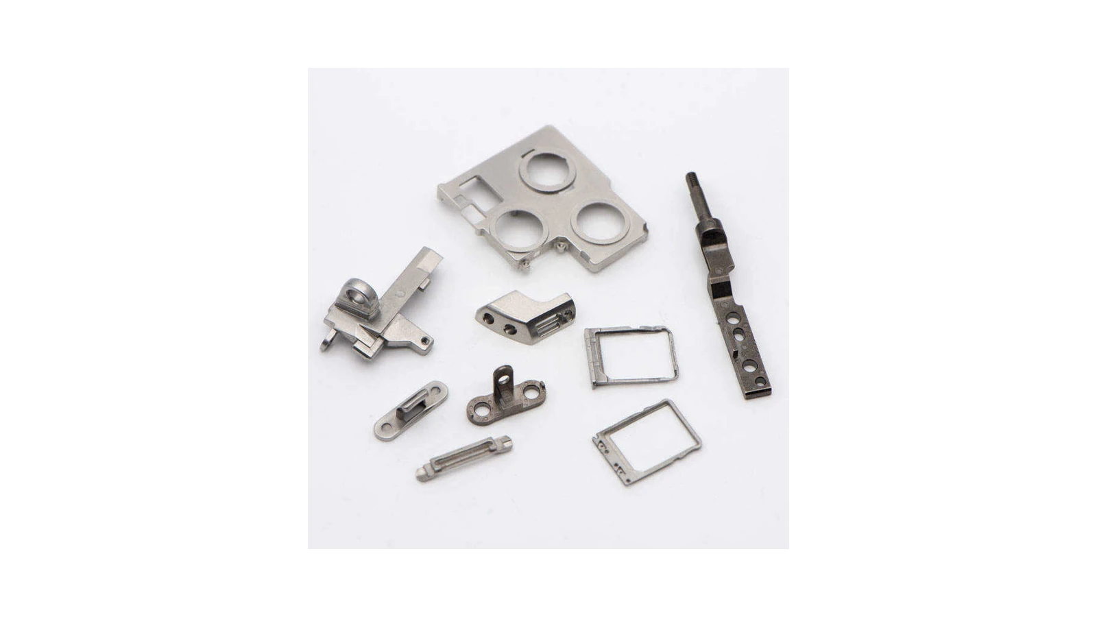
Real XTMIM metal injection molded parts for mobile phone and consumer electronics component review
Real MIM Part Evidence
Real XTMIM MIM parts used to illustrate compact consumer-electronics component families. Final suitability still depends on the customer drawing, material, finish, assembly interface, and annual volume.
MIM tooling and drawing engineering review before consumer electronics tooling release
Drawing and Tooling Review
Engineering-review reference visual for checking geometry, datums, cosmetic zones, tolerances, material, finish, and RFQ inputs before tooling. It is not a disclosed customer drawing.
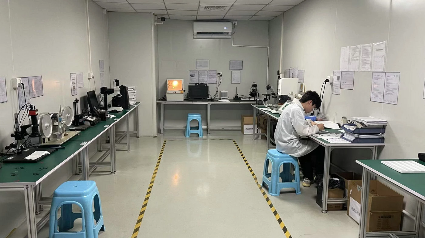
Real XTMIM quality inspection workshop for dimensional and visual acceptance review
Real Inspection Evidence
Real XTMIM inspection-workshop evidence supporting dimensional, visual, and project-specific acceptance planning after molding, debinding, sintering, and required secondary operations.
Program Review Matrix

Qualification, Deeper Review and RFQ Evidence

A consumer electronics component should move toward MIM tooling only when the engineering team can connect geometry, appearance, assembly fit, material, product economics, and acceptance criteria. The matrix below separates an initial qualification signal from issues that require deeper review and the evidence needed for quotation.

Review Area Qualification Signal Deeper Review Trigger RFQ Evidence Needed
Geometry Qualification
Small, feature-dense metal geometry or a clear opportunity to consolidate machined or assembled features.
Review
Large simple form, abrupt thick-to-thin transitions, unsupported thin features, or local mass likely to affect distortion.
2D drawing, 3D CAD, overall dimensions, wall sections, undercuts, functional features, and preferred parting or gate restrictions.
Cosmetic Surfaces Qualification
Visible, hidden, and post-finished zones are separated before tooling.
Review
Appearance requirements are defined only after samples, or all surfaces are treated as equally cosmetic-critical.
Surface-zone map, finish specification, texture or appearance reference, edge requirements, and protected areas.
Assembly Interfaces Qualification
Critical datums, mating features, motion interfaces, and assembly priorities are identified.
Review
Every dimension is treated as critical, or mating-part information is unavailable.
Critical-dimension list, datum scheme, mating-part data, fit or movement requirement, and inspection method.
Material and Finish Qualification
The alloy direction is reviewed together with corrosion, wear, appearance, and post-finish needs.
Review
A grade is named without functional requirements, or polishing, plating, coating, or PVD is added late.
Material target, performance priorities, finish route, coating or plating specification, and restricted surface zones.
Product Lifecycle and Volume Qualification
Stable repeat demand or a component family can support tooling and process development.
Review
The product cycle is short or uncertain, the quantity is low, or the comparison only considers prototype piece price.
Annual volume, expected program life, ramp schedule, forecast range, and current manufacturing route.
Inspection and Acceptance Qualification
Dimensional, functional, cosmetic, and post-finish acceptance criteria are defined before first samples.
Review
Acceptance depends on subjective sample review without agreed datums, visual zones, or measurement conditions.
Inspection plan, critical characteristics, cosmetic acceptance criteria, gauges or test method, and packaging or handling requirements.

The matrix is a pre-tooling screening tool, not a universal capability promise. Final feasibility depends on material, geometry, tooling, debinding, sintering, secondary operations, finish route, inspection method, and project-specific acceptance criteria.

Representative Review Scenarios

Representative Consumer Electronics MIM Review Scenarios

These scenarios show why a part can appear suitable at concept stage but still require coordinated geometry, finish, tolerance, and program-economics review before tooling.

Scenario 1: Cosmetic Surface Beside Dense Hidden Geometry

Problem

A small visible component meets basic dimensions, but appearance variation becomes noticeable after polishing, coating, or final handling.

Cause

The cosmetic outer surface is connected to a dense hidden zone, while visible surfaces, wall transitions, and the finish route were not reviewed together before tooling.

Handling

Separate visible and hidden zones, review local mass and wall transitions, align the material with the finish route, and reserve secondary operations only for features that require them.

RFQ Evidence

2D drawing, 3D CAD, cosmetic-zone map, finish specification, acceptable visual reference, and critical assembly dimensions.

Scenario 2: MIM Compared Only with Machined Piece Price

Problem

A program rejects MIM after comparing one machined part price with one molded part price, without evaluating the complete component or assembly route.

Cause

The comparison omits feature consolidation, machining operations, assembly steps, post-finish requirements, tooling amortization, scrap exposure, and repeat volume across the product lifecycle.

Handling

Compare the total manufacturing and assembly route under the expected annual volume and program life, while keeping critical secondary operations visible rather than assuming MIM removes every process.

RFQ Evidence

Current process route, machining and assembly steps, annual volume, program duration, finish requirements, and the dimensions that must remain secondary-machined.

Disclosure: these are representative engineering review situations, not disclosed customer projects or guaranteed production outcomes.

Submit a Consumer Electronics Component for MIM Review

Send the 2D drawing, 3D CAD file, material or performance target, cosmetic zones, critical assembly dimensions, finish requirements, annual volume, and expected product lifecycle. The review should confirm MIM fit before tooling and quotation.

FAQ

Consumer Electronics MIM Questions Users Actually Ask

Small, precise, and geometrically complex metal parts produced in repeat volumes are usually the strongest candidates. Earbud frame parts, miniature hinges, SIM-related parts, structural inserts, and wearable hardware are common examples.

No. Large, simple, low-complexity, or low-volume parts may still be better served by machining, stamping, die casting, or another process depending on geometry and product cycle.

Because electronics parts are often judged by both appearance and function. Visible surfaces, edge quality, polishing, coating, and other finish requirements can strongly affect the manufacturing plan.

Some dimensions can be controlled through the molding and sintering route, but assembly-critical features often benefit from a planned tolerance split and selective secondary operations.

Review geometry fit, cosmetic zones, finish route, assembly-critical dimensions, material choice, product cycle, and volume logic before tooling is released.