MIM Process Quality Mold design affects MIM part quality because it controls how feedstock fills the cavity, how balanced the green part density becomes, how fragile features are supported during ejection, and how predictably the part shrinks during debinding and sintering. A mold that fills the cavity is not automatically a mold that produces stable …
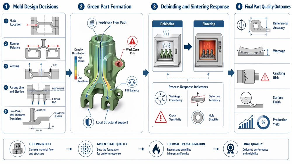
Mold design affects MIM part quality because it controls how feedstock fills the cavity, how balanced the green part density becomes, how fragile features are supported during ejection, and how predictably the part shrinks during debinding and sintering. A mold that fills the cavity is not automatically a mold that produces stable final parts. Gate location, runner balance, venting, parting line placement, ejector support, core-pin stability, and shrinkage-sensitive geometry can all create hidden quality risks that appear later as warpage, cracking, dimensional drift, flash, surface defects, or unstable hole positions. For this reason, MIM mold design should be reviewed as an early part-quality decision, not only as a tooling construction task.
This article is part of XTMIM’s MIM part quality series. For the broader quality-control framework, start with what affects part quality in MIM, then use this page to evaluate the mold-related risks that should be reviewed before tool release.
Engineering note: In MIM, a mold that produces a complete green part can still produce unstable sintered parts if filling balance, density distribution, and weak-feature support were not designed correctly from the beginning.
Key takeaway: Many final MIM quality problems begin as mold design problems long before the part reaches the furnace.
Why Mold Design Matters So Much in MIM
In this quality-control series, mold design is the bridge between part geometry, injection molding behavior, and downstream process stability. According to the Metal Powder Industries Federation (MPIF), the MIM process combines fine metal powder feedstock, injection molding, debinding, and sintering into a single manufacturing route. MIMA’s process overview also highlights MIM’s ability to produce complex parts with good dimensional tolerance control and support high-volume multi-cavity production. That process chain matters because the condition of the green part strongly affects everything that happens later.
If the tool creates uneven flow, trapped air, weak joins, or unstable local density, the part may not fail immediately. Instead, the defect may show up later as distortion, cracking, hole movement, dimensional drift, or cosmetic inconsistency.
This is why mold design should never be reviewed only as a tooling cost issue. It is a part-quality issue. A lower-cost mold concept may still become the more expensive production choice if it increases tool adjustment time, scrap, dimensional instability, or repeated trial cycles.
The practical engineering logic is simple: mold design shapes green part uniformity, green part uniformity shapes thermal-process stability, and thermal-process stability shapes final part quality. For projects that are still in drawing review, the dedicated MIM mold design guide can help connect this quality logic back to DFM decisions before tooling starts.
Where Mold Design Influences Part Quality Most
The most useful mold-quality review is not a generic tooling checklist. It asks where the mold can create flow imbalance, trapped air, green-part weakness, unsupported geometry, or density variation that later becomes a final-quality defect. The following areas usually deserve the closest review before tool release.
1. Gate Location and Runner Balance
Gate location is one of the most influential decisions in MIM tooling. It controls how material enters the cavity, how far the flow front must travel, where weld lines form, and how pressure is transmitted into different areas of the part. A poor gate position can still produce a filled green part, but it often creates hidden risk in the form of density imbalance, weak rejoining areas, cosmetic defects, and later shrinkage instability.
When critical holes, thin sections, flat faces, or sharp transitions sit near poor flow-rejoin zones, the quality risk rises significantly. In production, these issues often appear as unstable dimensions, local deformation, or unpredictable variation between batches and cavities. For a deeper review of this specific decision, see the dedicated guide to MIM gate design.

Key takeaway: A part may still fill with poor gate placement, but filling success does not guarantee balanced density or stable shrinkage.
This engineering logic is also supported by published literature. A 2026 process-optimization study on high-precision MIM parts noted that gate position strongly influences flow behavior, residual stress, and shrinkage distribution. A 2024 shrinkage study likewise reported that much of the shrinkage variation in MIM comes from density inhomogeneity already created in the green molding stage. In practical terms, this means gate strategy is not just a filling decision. It is a final-quality decision.
Sources: International Journal of Advanced Manufacturing Technology – 2026 gate-position study | Analysis of Shrinkage in Metal Injection Molding (2024)
2. Venting and Trapped Air Control
Venting is often underestimated in early tooling discussions, but it has a direct effect on cavity filling stability and surface integrity. If air cannot escape effectively, the result may be incomplete fill, localized burn-like marks, unstable surface finish, or internal weakness in hard-to-fill features.
In MIM, this matters even more because the feedstock behavior is not the same as ordinary plastic molding. If the cavity fill is already unstable at the molding stage, later process steps will not restore uniformity. Poor venting should therefore be treated as a part-quality risk, not simply a mold-detail issue.
3. Parting Line and Ejection Strategy
Parting line design affects flash risk, feature fidelity, and cosmetic quality. Ejection strategy affects whether the green part leaves the cavity with stable support or with local deformation. If ejector force is concentrated near fragile sections, thin walls, or unsupported protrusions, the green part may leave the mold with hidden stress or slight distortion that becomes more severe during later process stages.
These details are especially important when critical faces must remain clean, flat, sealed, or dimensionally stable. Poor parting line placement and ejector layout may not always cause immediate rejection, but they often reduce the process window and increase adjustment difficulty during trials.
4. Core Pins, Holes, Thin Walls, and Section Transitions
Sensitive geometry and mold design must always be reviewed together. Deep blind holes, slender core pins, thin unsupported walls, abrupt thickness changes, and large flat surfaces all increase the difficulty of stable molding and stable shrinkage. The issue is not simply that these features are hard. The real issue is that they are more sensitive to local density variation, ejection stress, and distortion during debinding or sintering.
The Metal Injection Molding Association design guidance emphasizes the importance of cavity design, draft, fillets, hole orientation, and parting-line strategy because these factors directly influence dimensional capability and manufacturability. In practice, the highest tooling risk usually comes from the interaction between geometry and tool layout, not from one isolated feature alone.

Key takeaway: The highest mold-related quality risk usually comes from the interaction between sensitive geometry and tooling layout, not from one isolated feature alone.
Mold Design Does Not Stop at Cavity Fill
One of the most common mistakes in MIM project reviews is to judge mold success too early. A part that fills completely and ejects successfully is only at the beginning of the real quality test. The more important question is whether the molded green part is uniform enough to survive debinding and sintering with stable shrinkage and acceptable final geometry. This is why mold design should be reviewed together with injection molding quality and debinding and sintering quality, not as an isolated tooling topic.
This is where mold design has a lasting influence. If gating, venting, support, and section transition logic are balanced, the green part is more likely to behave predictably during thermal processing. If the mold creates uneven density or local weakness, the later signs often appear as:
- warpage after sintering
- dimensional drift in critical features
- cracking in thin or stressed regions
- hole movement or flatness instability
- greater variation from batch to batch
Published sintering research has shown why this happens. A 2015 study on stress evolution in MIM parts reported that low-density regions shrink faster than high-density regions during sintering, which creates internal stress and promotes distortion risk. In other words, many furnace-stage symptoms are actually upstream mold-stage problems in disguise.
Source: Evolution of stresses in metal injection molding parts during sintering (2015)
What Engineers Should Review Before Tool Release
A strong MIM tooling review should focus on quality logic, not only on whether the tool can be built. Before releasing a mold design, the engineering team should check whether the tooling strategy supports the part’s real quality priorities: dimensional accuracy, surface condition, flatness, hole stability, strength-sensitive regions, and long-run repeatability. This is also where an early MIM tooling review can connect drawing features, gate strategy, trial feedback, and downstream quality targets before expensive tool changes are needed.
Gate position
Confirm that the flow path supports critical features instead of creating weak rejoin zones near them.
Runner and fill balance
Review whether material reaches sensitive regions in a stable and predictable sequence.
Venting
Reduce trapped-air risk and protect fill stability in thin or closed-end regions.
Parting line placement
Keep flash risk and mismatch away from critical surfaces and appearance faces.
Ejection support
Protect fragile green-part regions from local stress and deformation during release.
Section transitions
Check whether abrupt thickness changes or unsupported details will increase distortion risk.
Shrinkage-sensitive geometry
Identify holes, flat faces, thin walls, and long unsupported areas that need extra review.
Quality target alignment
Make sure the tool concept matches the actual tolerance and performance expectations of the project.

Key takeaway: The lowest-cost time to fix mold-related quality risk is before tooling release, not after trial parts start failing.
Standards and material data still matter in this stage. For example, engineers commonly refer to MPIF Standard 35-MIM when discussing baseline material properties and project expectations. MPIF also announced the 2025 edition update for materials standards used in metal injection molded parts. Strong material data is important, but it cannot compensate for a tooling concept that creates unstable green-part conditions from the beginning.
Sources: MPIF Standards | MPIF – Materials Standards for Metal Injection Molded Parts, 2025 Edition
Representative Engineering Scenario: When Mold Risk Appears After Sintering
A representative MIM tooling review often starts when trial molding looks acceptable, but sintered parts later show hole drift, flatness variation, or localized distortion. In this situation, the first assumption is often that the furnace profile needs adjustment. That may be partly true, but the engineering team should also review whether gate position, runner balance, venting, ejector support, and local wall transitions created uneven green density before thermal processing began.
This type of scenario is not a single customer case. It is a common engineering pattern in MIM project reviews: the defect appears after debinding or sintering, but the root cause may have been introduced by the mold. Reviewing the tool concept together with part design, material behavior, and process control usually gives a clearer path than adjusting furnace parameters alone.
Common Mistakes That Look Like Sintering Problems but Start in the Mold
“The furnace caused the warpage.”
Sometimes yes, but often the root cause begins earlier with unbalanced filling, weak support, or geometry that was placed in a density-sensitive tooling condition. The furnace may reveal the problem, but it did not necessarily create it.
“The part filled, so the mold is fine.”
Filling is only one checkpoint. The more important question is whether the green part is uniform enough to shrink consistently later. A successful fill does not prove a stable process window.
“We can correct it later with process tuning.”
Process tuning can help around the edges, but it rarely fixes a fundamentally weak gating, venting, ejection, or support concept. Poor tooling logic usually returns as variation, low yield, or extended trial time.
“Tooling complexity automatically improves quality.”
Not always. More slides, inserts, and complicated tool actions can make some geometries possible, but they can also add tolerance stack-up, maintenance demand, and new instability points. The best tooling is usually the simplest robust design that protects the real quality target.
Referenced Standards, Design Guidance, and Literature
For engineering teams evaluating MIM tooling strategy, the most useful external references are not generic manufacturing articles, but formal standards, association design guidance, and process studies that connect molding-stage conditions to final dimensional and distortion outcomes.
-
MPIF Standard 35-MIM – material standards for metal injection molded parts.
View MPIF Standards -
MPIF 2025 Edition Notice – confirms the current update cycle and newly added or updated MIM materials.
Read the 2025 edition announcement -
MIMA – Complex Designs with MIM – explains why mold cavity design inherently sets an important limit on dimensional control.
Read the design guidance -
MIMA – Process Overview: MIM – outlines MIM capability for complex shapes, dimensional control, and multi-cavity production.
Read the process overview -
Analysis of Shrinkage in Metal Injection Molding (2024) – shows that shrinkage variation in MIM is strongly linked to density inhomogeneity formed during injection molding.
Read the shrinkage study -
Gate-position optimization study (2026) – highlights the influence of gate position on flow behavior, residual stress, and shrinkage distribution in precision MIM parts.
Read the gate-position study -
Evolution of stresses in metal injection molding parts during sintering (2015) – shows why density differences can create stress and distortion during sintering.
Read the sintering-stress study
Related Articles in This MIM Part Quality Series
Mold design is only one quality driver. Use the related articles below to review how part design, material selection, feedstock, injection molding, debinding, sintering, and dimensions work together to influence final MIM part quality.
What Affects Part Quality in MIM?
How Part Design Affects Part Quality in MIM
How Material Selection Affects MIM Part Quality
How Feedstock Affects Part Quality in MIM
How Injection Molding Affects Part Quality in MIM
How Debinding and Sintering Affect Part Quality in MIM
How Part Dimensions Affect Final MIM Part Quality
Conclusion
Mold design is one of the earliest and strongest quality drivers in MIM. It affects how the feedstock fills, how stable the green part becomes, how predictable debinding and sintering are, and how consistent the final part remains in mass production.
The most important lesson is this: a mold that can produce parts is not necessarily a mold that can produce quality parts consistently. Good MIM tooling should not only fill the cavity. It should build the right quality foundation for the entire process chain that follows.
For that reason, the best mold reviews are never isolated tooling reviews. They are part-quality reviews carried out early enough to prevent expensive downstream corrections.
If your drawing includes thin walls, deep holes, flatness-sensitive faces, tight positional tolerances, or complex gating constraints, you can submit your MIM drawing for review before tool release so mold-related quality risks can be checked earlier.
Frequently Asked Questions
These questions focus on the practical relationship between mold design and final MIM part quality.
Mold design affects how the feedstock fills, packs, vents, ejects, and forms the green part. If the mold creates unstable flow, weak support, or local density imbalance, the final result may become visible later as warpage, cracking, dimensional drift, flash, or surface defects.
Gate location influences flow direction, weld-line position, pressure transfer, and local packing behavior. A poor gate strategy can place weak rejoin zones near critical features and increase the risk of uneven density, distortion, and unstable shrinkage.
Yes, indirectly. The mold does not control sintering by itself, but it controls the quality and uniformity of the green part. Better filling balance, venting, ejection support, and geometry handling improve the chance of stable shrinkage during later thermal processing.
These details affect flash risk, cosmetic quality, and the stability of the green part during ejection. If a parting line or ejector mark lands on a critical sealing face, appearance face, or precision area, the quality risk rises immediately.
No. Slides, inserts, and complex actions can make certain geometries possible, but they can also add tolerance stack-up, maintenance needs, and extra sources of instability. The best tooling is usually the simplest robust design that protects the real quality target.
The best time is before tooling release. Mold design should be reviewed together with part geometry, material selection, tolerance targets, surface requirements, and post-sinter operations. Fixing mold-related quality problems after tool build is usually slower and much more expensive.