طلب عرض سعر للقولبة بالحقن المعدني

شارك الرسم الخاص بك، متطلبات المواد، الكمية السنوية، احتياجات التفاوتات، أو تفاصيل التطبيق. سيقوم فريقنا الهندسي بمراجعة مشروع MIM الخاص بك والرد بتعليقات فنية أو عرض سعر.

Metal Injection Molding Services

XTMIM provides metal injection molding services for small, complex OEM parts. Injection molding, debinding and sintering take place in-house at our Dongguan facility. Drawing reviews identify tooling constraints, any required machining or finishing, and the inspection criteria for the finished part.

01 · Service scope

Our Metal Injection Molding Services

A complete MIM quotation must account for both the sintered part and any work needed to meet the finished drawing. We review critical features, define the trial inspection plan, and identify sizing, machining or surface treatment before tooling is finalized. The RFQ establishes which operations XTMIM performs and which require specialist partners.

01

Engineering Review and Tooling Support

During DFM review, we examine gate and parting-line locations, fragile features before sintering, shrinkage-sensitive dimensions and assembly datums. Specialist toolmakers develop the mold with our engineering input. Measurements from sintered trial parts are used to identify where tool corrections are needed.

  • Review geometry, assembly datums and critical-to-quality features
  • Agree molding and tooling risks with the specialist mold supplier
  • Use measured T0/T1 sample deviations to plan corrections
02

In-House Injection Molding, Debinding and Sintering

Injection molding, green-part handling, debinding and sintering take place in-house. Trial parts are checked for filling or ejection defects, damage during binder removal, and distortion after sintering. The sintered dimensions and surface condition—not just the molded green part—determine whether the process is ready for approval.

  • Review molded and debound condition before furnace processing
  • Evaluate sintered shape and surface condition
  • Feed trial measurements back into tooling and processing decisions
03

Secondary Machining and Finishing Services

Depending on the finished drawing, a part may need sizing, selective CNC machining, grinding, polishing, blasting, passivation, plating or PVD. These operations are reserved for features that need them: machining surfaces that can remain as-sintered would reduce MIM's near-net-shape cost advantage.

  • Identify functional holes, threads and reference faces that need finishing
  • Protect cosmetic zones and allow for coating or finishing effects
  • Measure the part in its specified final condition

Injection molding, debinding and sintering are carried out in-house. XTMIM works with specialist tooling and finishing suppliers where needed. The agreed process plan identifies as-sintered dimensions, features requiring post-processing and final inspection points. See our manufacturing capability details.

02 · Parts & applications

Custom MIM Parts We Manufacture

These parts from the XTMIM portfolio illustrate three common manufacturing challenges: mounting-hole alignment, hinge fit and mounting-face flatness. The engineering points below explain what to check on a customer drawing; they are not inspection results from the pictured components.

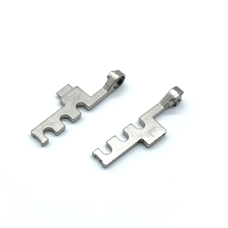
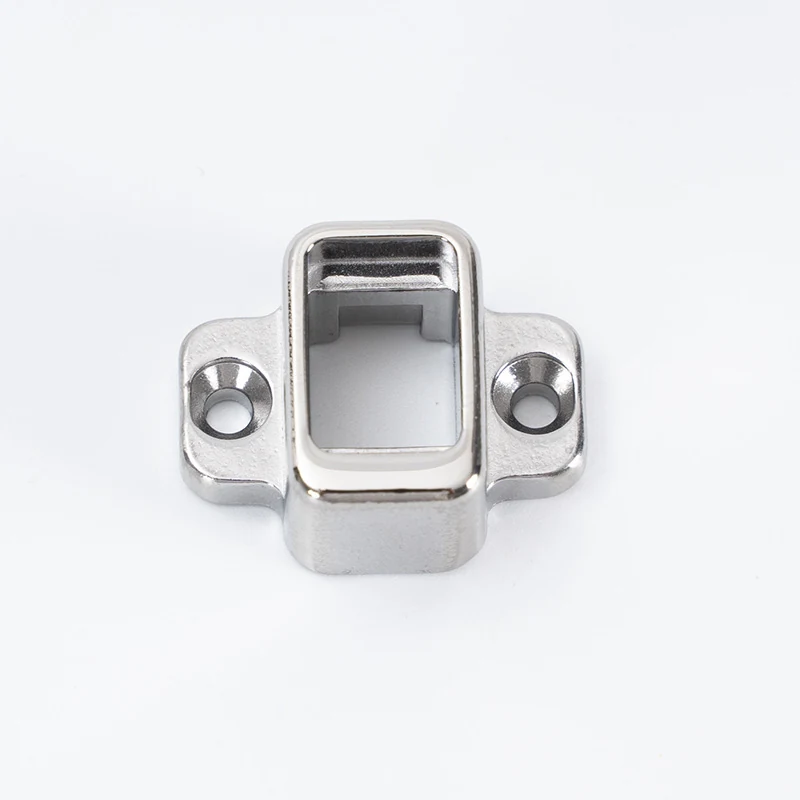
304 stainless steel compact mobile phone bracket with two fixing holes

304 Stainless Steel Phone Bracket

The open frame and mounting holes combine several locating functions in one compact part. Hole positions relative to the assembly datum may need close control, while noncritical outer surfaces may remain as-sintered.

On the drawing: identify the locating face and hole-position tolerances. If either feature needs finishing, confirm that a tool can reach it after sintering.

View MIM bracket parts →
Small metal hinge components with pivot holes and shaped mounting features

مكون مفصل شاشة الهاتف الذكي

A pivot bore can meet its diameter tolerance yet still bind during assembly if sintering moves its axis relative to the mating datum. Local wall distribution and the condition of the contact surfaces also affect the final fit.

On the drawing: specify the bore position relative to the functional datum and the intended fit. Confirm whether final-condition gauging or selective bore machining is required.

View MIM hinge parts →
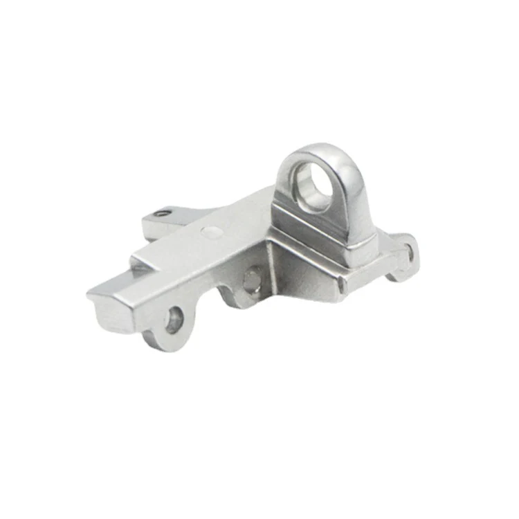
Compact laptop bracket component with mounting boss and several formed features

Laptop Bracket with Mounting Features

Bosses, arms and steps integrate several mounting functions in one component. Uneven section thickness and contact with the sintering support can produce differential shrinkage or distortion at mounting faces.

On the drawing: mark the assembly datum and required flatness. A trial can establish whether support changes or selective machining are needed to hold that requirement.

Explore compact MIM parts →

Explore additional shapes in the custom MIM parts portfolio. Material certificates, dimensional results and production requirements are confirmed for each drawing and approved manufacturing route.

03 · Manufacturing evidence

In-House MIM Manufacturing Capabilities

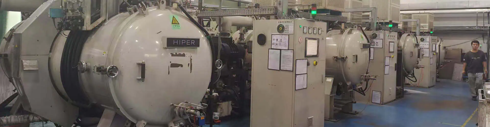
Our Dongguan facility brings injection molding, debinding and sintering together with sizing and dimensional-inspection support. For a specific alloy and geometry, we use sintered sample measurements to assess the chosen furnace route, required finishing and final acceptance criteria before repeat production.

  • Molding and trial production: green-part filling, ejection, visible defects and dimensional results are reviewed through sintered trials, not just mold acceptance.
  • Debinding and sintering: in-house furnace routes include vacuum and continuous arrangements; suitability is confirmed for the selected material and part, rather than assumed across all alloys.
  • Post-sintering processing: sizing and selective machining are considered only for features that cannot economically meet final requirements as-sintered.
  • Inspection feedback: CMM and optical measurement resources support datum-related and small-feature checks; material or surface tests are defined where required by specification.

The proposed manufacturing route will identify the furnace process, in-house operations, partner-managed finishing and the inspection points required by the drawing. You can also review our جولة في المصنع, manufacturing capability و inspection resources.

Key details for your manufacturing plan

  • In-house molding, debinding and sintering route
  • Toolmaker and finishing responsibilities
  • Sample inspection method and acceptance criteria
  • Production controls required for repeat orders

Sintered trial parts are measured against the drawing to verify critical dimensions before release.

XTMIM factory tour overview of the production environment
Factory tour overview
04 · Project fit

Is Metal Injection Molding Right for Your Part?

MIM is worth evaluating when the geometry is difficult or costly to machine and recurring demand can justify a dedicated tool. Most features should remain near-net shape; material availability, sintering distortion and finishing costs still affect feasibility. Small size alone does not make a part suitable for MIM.

✓ A stronger MIM candidate
  • Small or compact part with multiple complex features such as ribs, slots, bosses, holes or integrated functions.
  • Recurring orders with sufficient volume to spread tooling and development costs.
  • Established material grade and a drawing that defines critical fit and appearance requirements.
  • Potential to reduce extensive CNC operations or consolidate a multi-piece assembly.
! Review another process first
  • Very low quantities or prototypes whose design is likely to change repeatedly.
  • Large, simple, thick or highly asymmetric geometry with avoidable sintering risk.
  • Nearly every surface needs extremely tight machining tolerances.
  • A stamped, machined, cast or pressed part may meet the drawing more economically.

Before opening a MIM tool: confirm that the design is stable, identify which dimensions truly need post-sintering machining, and compare the tooling investment with recurring order demand. If these conditions do not align, CNC or another process may be more economical. See our manufacturing process comparisons.

05 · Material & finish

MIM Materials and Finishing Options

For MIM parts, the alloy grade alone does not define finished-part performance. Heat treatment, density, corrosion exposure and finishing can affect strength, dimensions and service life. XTMIM primarily evaluates established steel and stainless-steel routes; nonstandard grades require a separate manufacturing review.

Available MIM Materials

عائلة الموادCommon grades reviewedProcurement / engineering decision
Austenitic stainless steels304، 316LCorrosion exposure, surface appearance and any required passivation or coating.
فولاذ مقاوم للتصلب بالترسيب17-4 PHRequired strength and final heat-treatment condition.
Martensitic stainless steels420، 440CHardness, wear behavior, heat treatment and distortion risk.
الفولاذ منخفض السبائك4140, 4340, 4605Mechanical loading, heat treatment, corrosion protection and manufacturing volume.

Grade availability and the manufacturing route are confirmed at quotation; the table does not imply that every feedstock is held in stock. Specify any required heat-treated condition and acceptance standard. The MPIF Standard 35-MIM materials reference provides relevant industry specifications, while your drawing and agreed tests define final acceptance. See our MIM materials library.

Secondary Finishing and Functional Requirements

Dimensional finishing

Plan CNC finishing, sizing or grinding only where locating faces, bores, threads or other critical features cannot reliably meet the drawing as-sintered. Define datums and measurement access before the tool is made.

Surface preparation

Polishing, tumbling, blasting and cleaning change appearance, edge condition and sometimes critical surfaces. Identify cosmetic zones, roughness targets and faces that must not be rounded.

Functional treatment

Heat treatment, passivation, plating or PVD may be considered when compatible with the alloy and end use. A coating on a tight-fit bore or mating surface can change clearance, so specify coating limits, masking needs and the final dimension to be measured after finishing.

Identifying cosmetic areas, roughness limits, coating thickness and fit-sensitive surfaces in the RFQ allows machining allowances, masking and final inspection to be planned before tooling.

06 · Program development

From Drawing Review to MIM Production

Mold completion does not release a MIM part for volume production. First, sintered samples—and finished samples where applicable—must be checked against the drawing. Trial measurements may lead to tool corrections, processing changes or additional finishing before sample approval.

01Drawing & feasibility review

We review critical-to-quality dimensions, datums, alloy, finish and annual demand, then identify design risks and the proposed manufacturing route.

02Tooling plan & development

The tooling plan sets cavity layout, gate and parting-line locations, shrinkage allowance and measurement access with the mold supplier.

03Trial molding & sintered samples

Sintered and, where needed, finished samples are measured against the drawing datums. The deviation pattern guides any tool correction, support change or secondary operation.

04Sample verification & approval

Check assembly fit, CTQ dimensions, final material condition and finishing; approve the drawing revision and inspection method before production release.

05Volume production & control

Manufacture using the approved route and agreed control points, sampling, packaging and repeat-order requirements; manage later changes against the approval baseline.

Example — mounting-hole alignment: A trial bracket can meet its overall dimensions while a mounting hole sits outside its positional tolerance relative to the locating face. Before approving the sample, verify the datum and measurement setup, examine the sintered deviation pattern, then assess tooling compensation, support changes or selective machining. This is an illustrative engineering scenario, not a customer test record. See our project development support.

07 · Quality & verification

Quality Control and Dimensional Verification

The inspection plan begins with drawing datums and critical-to-quality dimensions, before tooling is cut. A feature that changes during machining, heat treatment or coating is checked again in the specified final condition; passing an earlier inspection does not establish final assembly fit.

Critical Dimensions and Post-Sintering Control

Tool shrinkage compensation addresses expected overall reduction, but local warpage can arise from uneven wall distribution, loading or support during sintering. Measure critical bores, flatness and positions relative to functional datums on trial samples; then choose tooling correction, support revision or selective finishing based on the deviation pattern.

  • Define datum scheme, fit and functional tolerances
  • Check wall balance, support surfaces and distortion risk
  • Agree final measurement condition after finishing

Inspection and Production Consistency

XTMIM uses CMM and optical measurement resources for dimensional checks. CMM measurements can establish positions relative to datums and mating-face relationships; optical methods can help inspect small slots and profiles where contact probing is difficult. The drawing and inspection plan should identify the method, datums, sample size and acceptance limits before sample approval.

  • First-sample and final-condition verification
  • In-process feedback between molding and sintering
  • Agreed inspection records and repeat-order controls
مخاطر محتملةPlanned control / verificationWhat the buyer should define
Post-sintering dimensional shiftTool compensation, trial measurement, support and selective sizingCritical features, datums, drawing tolerances
Material or heat-treatment mismatchConfirmed grade, applicable tests and final-condition validationMaterial standard, hardness or functional requirement
Finishing affecting fit or appearanceFinish allowance and final inspection after the specified operationRoughness, coating, appearance zones, corrosion exposure
Variation after sample approvalDefined manufacturing controls and agreed inspection checkpointsReceiving criteria, volume, traceability needs

Illustrative quality checks

Warped mounting face: If an asymmetric bracket passes the overall length check but fails mounting flatness after sintering, compare its wall transitions and contact points on the sintering support. Measure flatness against the functional datum across several trial samples; only then decide whether support changes, a geometry adjustment or selective machining can achieve the drawing. A visual inspection of the unsintered part would not detect this final-condition issue.

Finish-related fit: If a plated mating feature is accepted before coating but becomes too tight afterward, inspect coating buildup, masking and the specified final-size tolerance. Final acceptance must be based on the finished part where the drawing requires it.

As-sintered tolerances depend on the feature size, geometry, alloy and process conditions; critical fits may require selective finishing. See our مراقبة الجودة و الفحص والاختبار resources for the available checks.

08 · Commercial planning

MIM Tooling, MOQ, Pricing and Lead Times

A MIM quotation should separate one-time tooling from the recurring part price and state whether finishing, inspection and packaging are included. Tool fabrication, trial-sample approval and repeat production have different schedules. Comparing offers against the same drawing revision, order volume and inspection scope prevents misleading unit-price differences.

Buyer questionHow the project is handledUseful input for a quotation
Who owns the tool?The dedicated tool is customer-owned and is normally held at the factory. Maintenance, major corrections and transfer procedures belong in the tooling agreement.Ownership terms, storage/transfer needs and planned repeat orders
What are sample and production MOQs?Trial/sample quantities are separate from the first production order and later repeat-batch MOQ. Confirm the numerical requirement for each stage in the quotation.T0/T1 sample need, initial order, repeat-batch size and annual forecast
What is included in the unit price?Request an itemized distinction between one-time tooling, as-sintered part production, selective machining, coating, inspection and packaging.Material, drawing revision, finish, CTQs and comparable volume tiers
How are tooling and sample lead times planned?Request separate dates for tool fabrication, T0 sintered samples, possible tool corrections and customer approval. These activities can extend the initial development schedule.Target approval date, test requirements and approval decision maker
What is needed for repeat orders?Agree production release requirements, inspection or report format, packaging, batch schedule and any engineering-change approval before reorders.Demand forecast, receiving criteria and revision control

What a unit price may exclude: a lower as-sintered price can leave out machining, surface treatment, special inspection or tooling. Compare total cost at the same material condition, annual quantity and final-part acceptance requirements. A fuller explanation is available in our دليل تكلفة MIM.

09 · Start your project

طلب عرض سعر للقولبة بالحقن المعدني

Send your drawing package and estimated annual volume for an OEM MIM review. Our team checks process suitability, identifies geometry or tolerance risks and outlines the tooling, finishing and inspection scope needed for a quotation. Any missing requirements are identified before they become assumptions in the tool design or price.

What to include in your MIM RFQ

  • 2D drawing and 3D CAD: PDF plus STEP/STP where available.
  • المادة: preferred grade or required functional properties.
  • Volume: initial order, estimated batch size and annual demand.
  • الأبعاد الحرجة: fit features, datums, GD&T and assembly interfaces.
  • Finishing: cosmetic zones, surface roughness, coating, passivation or heat treatment.
  • Project requirements: target delivery window, approval/testing and any special notes.

Early-stage drawings are welcome. If material selection, tolerances or approval criteria are still open, mark them as pending so the engineering review can address them before pricing or tooling decisions are finalized.

What happens after you submit?

For a design still under development, use Drawing Review to resolve material, tolerance or process questions. If the drawing, expected order quantity and finishing requirements are defined, use Request a Quote for pricing.

  • Initial suitability and material-route review
  • Key geometry, shrinkage or tolerance concerns
  • Required secondary operations and inspection scope
  • Quotation inputs and proposed next development step

Drawings and CAD files are used for engineering review, quotation and project communication. For unreleased designs, discuss NDA arrangements before sending files.