إجابة سريعة: تؤثر مادة التغذية في عملية القولبة بالحقن المعدني (MIM) على جودة الجزء لأنها تتحكم في سلوك المسحوق المعدني والمادة الرابطة قبل الحقن، وإزالة المادة الرابطة، والتلبيد، والفحص النهائي. تدعم مادة التغذية المستقرة الملء المتسق للقالب، وقوة الجزء الأخضر، والإزالة الآمنة للمادة الرابطة، والانكماش المتوقع، والتحكم المتكرر في الأبعاد. التشتت السيئ للمسحوق والمادة الرابطة، أو التحميل الصلب غير المستقر، أو الرطوبة، أو المحتوى المتطاير، أو انحراف الريولوجيا، أو التباين من دفعة إلى أخرى…
إجابة سريعة: تؤثر مادة التغذية في عملية القولبة بالحقن المعدني (MIM) على جودة الجزء لأنها تتحكم في سلوك المسحوق المعدني والمادة الرابطة قبل الحقن، وإزالة المادة الرابطة، والتلبيد، والفحص النهائي. تدعم مادة التغذية المستقرة الملء المتسق للقالب، وقوة الجزء الأخضر، والإزالة الآمنة للمادة الرابطة، والانكماش المتوقع، والتحكم المتكرر في الأبعاد. يمكن أن يؤدي التشتت السيئ للمسحوق والمادة الرابطة، أو التحميل الصلب غير المستقر، أو الرطوبة، أو المحتوى المتطاير، أو انحراف الريولوجيا، أو التباين من دفعة إلى أخرى إلى ظهور عيوب لاحقًا مثل اللقطات الناقصة، أو الشقوق، أو الفجوات، أو الانتفاخ، أو الالتواء، أو عيوب السطح، أو انحراف الأبعاد. لمراجعة الجودة، لا ينبغي للمهندسين تأكيد أن حبيبات مادة التغذية يمكن قولبتها فحسب. بل يجب عليهم أيضًا تقييم اتساق المسحوق، وسلوك المادة الرابطة، وتوحيد الحبيبات، واستجابة الريولوجيا، وسلامة إزالة المادة الرابطة، وسلوك الانكماش، واستقرار الأبعاد الحرجة.
محور المراجعة الأساسي
جودة مادة التغذية، التحميل الصلب، الريولوجيا، سلوك المادة الرابطة، واتساق الدفعة.
مخاطر الجودة الرئيسية
لقطات قصيرة، تشققات، فراغات، اعوجاج، عيوب سطحية، واختلافات بعدية.
إجراء المشروع
راجع الرسومات، ومتطلبات المواد، والأبعاد الحرجة، واحتياجات التفاوت، والحجم السنوي قبل الموافقة على القالب أو الإنتاج.
يركز هذا المقال على المنطق التقني وراء هذه السلسلة. يشرح كيف تشكل خصائص المسحوق، وهندسة المادة الرابطة، والتحميل الصلب، وجودة التركيب، والريولوجيا جودة الجزء في إنتاج القولبة بالحقن المعدني الفعلي. كما يوضح كيف تتحول المشاكل المتعلقة بمادة التغذية إلى عيوب فعلية، وما الذي يجب على المهندسين مراقبته أثناء التطوير، وما الذي يجب على قسم ضمان الجودة التحقق منه قبل قبول دفعة مادة تغذية أو دفعة حبيبات مادة تغذية مزودة من طرف خارجي للتحقق من صحة الإنتاج.
إذا كنت بحاجة إلى الخلفية المتعلقة بجانب العملية قبل مراجعة مخاطر الجودة، فابدأ بـ دليل عملية مادة التغذية لـ MIM. لفهم جودة MIM كنظام كامل بدلاً من خطوات عملية معزولة، تعمل هذه المقالة أيضًا بشكل جيد مع نظرة عامة على القولبة بالحقن المعدني, دليل عملية MIM, ، و دليل مواد MIM.

الاستنتاج الأساسي: مادة التغذية ليست مجرد خطوة تحضيرية. بل هي جسر التحكم بين تصميم مسحوق المعدن والمادة الرابطة وجودة الجزء النهائي في MIM.
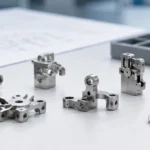
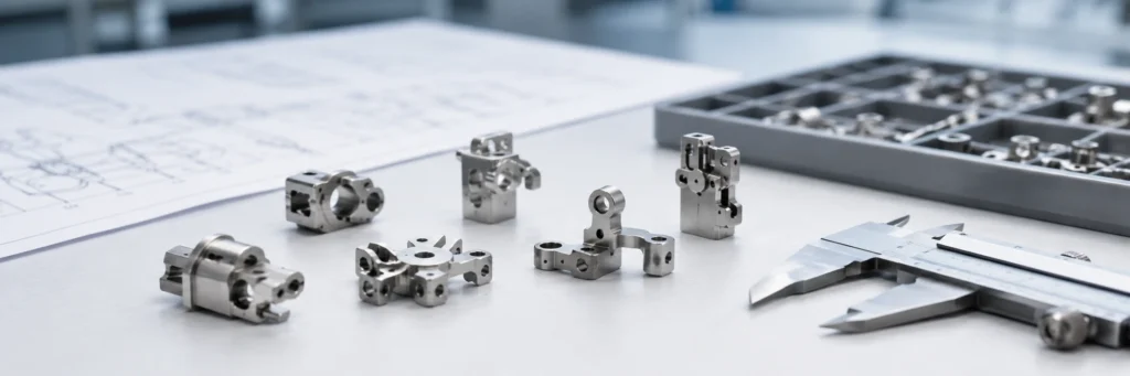
يوضح هذا الشكل لماذا لا ينبغي التعامل مع مادة التغذية كتفصيل أولي بسيط. فالمسحوق، والمادة الرابطة، والتحميل الصلب، ومرحلة الخلط لا تبقى منعزلة. فهي تؤثر بشكل مباشر على استقرار ملء القالب، وقوة الجزء الأخضر، وسلامة إزالة المادة الرابطة، واستجابة الانكماش، واتساق الكثافة، والتحكم النهائي في الأبعاد. إذا دخل التباين إلى العملية هنا، فإن المراحل اللاحقة غالبًا ما تقضي وقتها في التعويض عنه.
ما تتحكم فيه مادة التغذية حقًا في MIM
في MIM، مادة التغذية ليست مجرد خطوة تحضيرية. إنها المرحلة التي يتحول فيها المسحوق المعدني إلى نظام قابل للقولبة يجب أن يؤدي أداءً جيدًا ليس فقط أثناء الحقن، ولكن أيضًا أثناء المناولة، وإزالة المادة الرابطة، والتلبيد، والفحص النهائي. وفقًا لـ نظرة عامة على عملية جمعية القولبة بالحقن المعدني, ، يتم إنتاج مادة تغذية MIM عن طريق خلط مسحوق معدني ناعم جدًا مع مادة رابطة متعددة المكونات ثم تحبيب المادة إلى كريات للقولبة. هذا الوصف صحيح، ولكن في الإنتاج، السؤال الأكثر أهمية هو ما إذا كانت مادة التغذية تخلق نافذة عملية مستقرة أم تجبر كل مرحلة لاحقة على التعويض عن التباين الخفي.
تدعم مادة التغذية المستقرة خمس نتائج جودة على الأقل في نفس الوقت: ملء التجويف بشكل متسق، وقوة خضراء كافية، وإزالة آمنة للمادة الرابطة، وانكماش موحد، وكثافة نهائية قابلة للتكرار. بمجرد انهيار أحد هذه العناصر، غالبًا ما تتغير المشكلة شكلها أثناء انتقالها إلى المراحل اللاحقة. قد يبدو النقص في الملء أولاً كمشكلة في القالب أو الضغط. قد يبدو الشق أولاً كمشكلة في إزالة المادة الرابطة. قد يبدو الانحراف البعدي أولاً كمشكلة في الفرن. لكن في كثير من الحالات، يبدأ السبب الجذري الحقيقي داخل مادة التغذية نفسها.
الخلاصة الرئيسية: جودة مادة التغذية لا تتعلق فقط بجعل المسحوق قابلًا للحقن. إنها تتعلق ببناء جسر مستقر بين سلوك المسحوق، وأداء القولبة، وإزالة المادة الرابطة، واستجابة الانكماش، واتساق الجزء النهائي.
عوامل مادة التغذية التي تؤثر على عيوب واستقرار أجزاء القولبة بالحقن المعدني (MIM)
مادة تغذية MIM ليست مجرد مسحوق بالإضافة إلى مادة رابطة. إنها طور المسحوق، ونظام المادة الرابطة، والواجهة بينهما. لكل جزء من هذا النظام دوره الخاص، وتعتمد جودة الجزء النهائي على ما إذا كانت هذه الأدوار تظل متوافقة طوال سلسلة العملية.
| عامل المادة الأولية | ما الذي يتغير في الإنتاج | مشكلة جودة محتملة في أجزاء MIM |
|---|---|---|
| توزيع حجم جسيمات المسحوق | يغير سلوك التعبئة، وطلب المادة الرابطة، ومقاومة التدفق، واستجابة التلبيد. | تباين الأبعاد، خشونة السطح، عدم اتساق الكثافة، أو انكماش غير مستقر. |
| شكل المسحوق وحالته السطحية | يؤثر على الاحتكاك، وسلوك التدفق، والترطيب، وحساسية التلوث. | ملء ضعيف، مناطق ضعف محلية، عيوب سطحية، أو سلوك تلبيد غير طبيعي. |
| توازن نظام المادة الرابطة | يتحكم في قابلية التشكيل، وقوة الجزء الأخضر، ودعم الهيكل الأساسي، وسلوك إزالة المادة الرابطة. | تلف الجزء الأخضر، تشققات أثناء إزالة المادة الرابطة، بثور، تشوه، أو إزالة غير كاملة للمادة الرابطة. |
| التحميل الصلب | يتحكم في اللزوجة، مقدار الانكماش، تعبئة المسحوق، وعرض نافذة العملية. | لقطة قصيرة، ضغط حقن مرتفع، التواء، تشتت الانكماش، أو أبعاد غير مستقرة. |
| تجانس المسحوق والمادة الرابطة | يحدد ما إذا كانت مادة التغذية التي تدخل القالب موحدة حقًا. | عدم تطابق الكثافة المحلية، فراغات، أقسام ضعيفة، وانكماش تلبيد غير متناسق. |
| التحكم في الرطوبة والمواد المتطايرة | يغير توليد الغاز واستقرار التدفق أثناء القولبة أو إزالة المادة الرابطة. | فقاعات، شقوق، علامات سطحية، فراغات داخلية، أو عدم استقرار إزالة المادة الرابطة. |
| اتساق الدفعة مقابل الدفعة | يغير نافذة القولبة واستجابة الانكماش اللاحقة بين الدُفعات. | انحراف الأبعاد من دفعة إلى أخرى، جودة غير مستقرة، وتكلفة تعديل عملية أعلى. |
خصائص المسحوق
في جانب المسحوق، اختيار السبيكة هو مجرد نقطة البداية. يؤثر توزيع حجم الجسيمات على سلوك التعبئة، والطلب على المادة الرابطة، والريولوجيا، واستجابة التلبيد. يؤثر شكل الجسيمات على الاحتكاك، ومقاومة التدفق، ومدى سهولة تحرك المادة عبر المقاطع الرقيقة أو طويلة التدفق. كما أن حالة السطح والتلوث مهمة أيضًا. عادةً ما يدعم المسحوق الناعم نشاط تلبيد أفضل واستنساخ تفاصيل أفضل، ولكنه يزيد أيضًا من مساحة السطح، مما يميل إلى رفع الطلب على المادة الرابطة ويجعل مادة التغذية أكثر حساسية لعدم استقرار التدفق. لهذا السبب يجب مراجعة قرار المسحوق جنبًا إلى جنب مع نافذة القولبة المتوقعة وجودة الجزء المطلوبة، وليس بمعزل عن ذلك.
هذا المنطق مرتبط ارتباطًا وثيقًا بنظام المواد الأوسع. إذا لم تكن قد راجعت جانب اختيار السبيكة في المراحل السابقة بالفعل، فمن المفيد مقارنة هذا القسم مع دليل مواد MIM.
هندسة المادة الرابطة
المادة الرابطة هي أيضًا نظام وليس مكونًا واحدًا. في إنتاج MIM العملي، تدعم مكونات المادة الرابطة المختلفة وظائف مختلفة. بعضها يحسن التدفق أثناء القولبة. بعضها يوفر قوة هيكلية بحيث يمكن التعامل مع الجزء الأخضر دون تلف. والبعض الآخر يجعل إزالة المادة الرابطة ممكنة تحت مسار إزالة المادة الرابطة المختار. تشير نظرة عامة على عملية MIMA الملاحظات إلى أن اختيار المادة الرابطة مرتبط مباشرة بطريقة إزالة المادة الرابطة، وهذا الارتباط هو أحد أهم الحقائق الهندسية في MIM. يمكن لمادة تغذية تملأ التجويف جيدًا أن تصبح خيار إنتاج سيئًا إذا كان نظام المادة الرابطة لا يخلق مسار إزالة آمنًا للأقسام السميكة أو تركيز الكتلة المحلي أو انتقالات الجدار غير المتساوية.
لهذا السبب أيضًا لا ينبغي فصل عمل مادة التغذية عن سلسلة العمليات اللاحقة. إذا كان فريقك يراجع مخاطر إزالة المادة الرابطة في نفس الوقت، فمن الجدير قراءة هذه المقالة مع دليل عملية إزالة المادة الرابطة في MIM و دليل جودة إزالة المادة الرابطة والتلبيد.
الواجهة بين المسحوق والمادة الرابطة
الواجهة بين المسحوق المعدني والمادة الرابطة هي المكان الذي تبدأ فيه العديد من الأعطال الخفية. إذا كان التبلل ضعيفًا، أو كان التشتت غير كامل، أو حدث انفصال بين المسحوق والمادة الرابطة أثناء الخلط، فإن المادة التي تدخل القالب لم تعد متجانسة حقًا. قد يبدو أن التجويف يمتلئ، لكن مادة التغذية تحمل بالفعل تباينًا موضعيًا. لاحقًا، يظهر هذا التباين الخفي على شكل عدم تطابق في الكثافة الموضعية، أو أقسام ضعيفة، أو تشتت في الانكماش، أو عدم استقرار أبعادي.
سيناريو ميداني مركب للتدريب الهندسي: من الأخطاء الشائعة في المراحل المبكرة الموافقة على مادة تغذية لأن القولبة التجريبية تبدو مقبولة من الخارج. في الإنتاج الفعلي، قد تظهر نفس مادة التغذية لاحقًا تشوهًا موضعيًا بعد إزالة المادة الرابطة أو انكماشًا غير متناسق بعد التلبيد. السبب غالبًا لا يكون مرئيًا على السطح المقولب. قد يكون مشكلة في تجانس مادة التغذية أدت إلى تباين داخلي في الكثافة قبل أن يصل الجزء إلى الفرن.
لماذا يُعد التحميل الصلب أحد أكثر متغيرات مادة التغذية حساسية
الحمل الصلب في MIM غالبًا ما يُنظر إليه على أنه هدف تحسين بسيط، ولكنه في الواقع أحد أكثر المتغيرات حساسية في مرحلة المادة الخام (feedstock). يمكن أن يؤدي تحميل المسحوق الأعلى إلى تحسين التحكم في الانكماش وتقليل كمية المادة الرابطة التي يجب إزالتها. ومع ذلك، فإنه يزيد أيضًا من اللزوجة ويمكن أن يقلل من نافذة العملية بسرعة كبيرة. قد يؤدي تحميل المسحوق المنخفض إلى تسهيل التدفق، ولكنه غالبًا ما يزيد من الانكماش ويجعل التحكم البعدي النهائي أكثر صعوبة. لا توجد قيمة مثلى عالمية لأن النطاق القابل للاستخدام يعتمد على نظام المسحوق، ونظام المادة الرابطة، وهندسة الجزء، وظروف القولبة، وطريقة إزالة المادة الرابطة.
عقلية هندسية أكثر فائدة هي فصل التحميل الصلب الحرج عن تحميل التشغيل الإنتاجي. تخبرك القيمة الحرجة أين تبدأ مادة التغذية في فقدان استقرار التدفق العملي. يجب أن تكون قيمة الإنتاج عادةً في نافذة أكثر أمانًا أسفل هذا الحد. في دراسة تقنية منشورة, ، وهو نظام تغذية معدني قائم على الحديد يُستخدم في هذا النوع من التحميل الحرج ومراجعة نافذة القولبة العملية. الدرس المستفاد ليس نسخ رقم واحد. الدرس هو أن أفضل قيمة إنتاجية هي عادةً نافذة التشغيل الأكثر استقرارًا، وليس أعلى رقم يمكن المطالبة به.

الاستنتاج الأساسي: يجب اختيار التحميل الصلب لاستقرار العملية، وليس لأعلى قيمة ممكنة.
مادة تغذية ذات تحميل منخفض قد تتدفق بسهولة أكبر، لكنها عادةً ما تؤدي إلى انكماش أعلى وتحكم أضعف في الأبعاد. مادة تغذية ذات تحميل عالٍ جدًا قد تقلل الانكماش، لكنها غالبًا ما تزيد اللزوجة، وتضيق نافذة القولبة، وتزيد خطر ملء الأجزاء البعيدة. الهدف الأكثر عملية هو عادةً نافذة التشغيل المستقرة بينهما.
خطأ شائع في التوريد يحدث عندما تفترض الفريق أن أعلى تحميل مسحوق يجب أن يعني أيضًا أفضل مادة تغذية. في الإنتاج الفعلي، قد تصبح مادة التغذية المحملة بشكل عدواني شديدة الحساسية للضغط، وصعبة الملء في التجاويف طويلة التدفق، وأكثر عرضة لإنشاء أقسام رقيقة غير مملوءة بالكامل. قد يظل الجزء يُشكل، لكن العملية تصبح أقل تسامحًا ويصبح الحفاظ على استقرارية الدفعة أكثر صعوبة.
سيناريو ميداني مركب للتدريب الهندسي: أظهر أحد برامج الإنتاج التجريبي لجزء هيكلي صغير ملء غير مستقر في الطرف البعيد لعدة ميزات رقيقة. كان الافتراض الأولي أن تصميم البوابة يحتاج إلى إعادة عمل. ساعدت تغييرات البوابة بشكل طفيف فقط. المشكلة الأعمق كانت أن مادة التغذية كانت تعمل بالفعل بالقرب من حد التحميل العملي الأعلى. كانت النتيجة نافذة قولبة ضيقة وملء طرفي غير متناسق. بمجرد تعديل نافذة تشغيل مادة التغذية، امتلأ التجويف بشكل أكثر اتساقًا دون الحاجة إلى إعادة تصميم رئيسية للأداة.
لماذا تعتبر جودة الخلط والمركب أكثر أهمية مما تتوقع العديد من الفرق
حتى تصميم مادة التغذية المعقول يمكن أن يفشل إذا لم يتم التحكم في مرحلة المركب بشكل جيد. أ مراجعة فنية لمعالجة خليط المسحوق والمادة الرابطة يظهر أن جودة مادة التغذية تتأثر بشدة بوقت الخلط، ودرجة حرارة الخلط، وترتيب الإضافة، وخصائص المسحوق، وتركيبة المادة الرابطة، ومعدل القص، ونسبة تحميل المسحوق. بعبارة أخرى، الخلط ليس مجرد مهمة تحضيرية. إنها المرحلة التي تتحول فيها الصيغة النظرية إما إلى مادة تغذية قابلة للإنتاج أو تبقى مجرد وصفة مختبرية.
تؤثر درجة حرارة الخلط على ما إذا كانت المادة الرابطة تبلل المسحوق بشكل صحيح وما إذا كان المزيج يصل إلى بنية داخلية مستقرة. إذا كانت درجة الحرارة منخفضة جدًا، يظل التبلل والتشتت غير مكتملين. إذا كانت مرتفعة جدًا، قد يبدأ تدهور المادة الرابطة أو تطايرها أو انحراف التركيبة. وقت الخلط له نفس المخاطر ذات الوجهين. قصير جدًا، وتبقى التكتلات. طويل جدًا، وقد يؤدي التاريخ الحراري والقصي إلى إتلاف النظام أو زيادة خطر التلوث. ترتيب الإضافة مهم أيضًا. إذا تمت إضافة المسحوق بشكل سيئ أو بقوة شديدة، فقد يحبس المزيج مناطق غير متجانسة تنجو من التحبيب وتظهر لاحقًا كعدم اتساق بين الدفعات.
يرتبط التحكم في التركيب أيضًا بشكل مباشر باستقرار القولبة، لذلك من المنطقي عرض هذا القسم مع الدليل الخاص بـ كيف يؤثر القولبة بالحقن على جودة الأجزاء في MIM. إذا كانت دفعة مادة التغذية غير متسقة، يمكن لفريق القولبة التعويض فقط بقدر محدود باستخدام إعدادات الماكينة.
سيناريو ميداني مركب للتدريب الهندسي: في إحدى مرات التطوير، أظهر جزء دقيق بجسم مركزي أكثر سمكًا وعدة ميزات رفيعة في الأطراف ملءً غير مستقر فقط في الطرف البعيد. كان رد الفعل الأول هو إلقاء اللوم على موقع البوابة. أظهرت المراجعة الإضافية أن دفعة مادة التغذية كانت ذات نطاق لزوجة أضيق من الطبيعي بسبب خلط غير متسق. بمجرد تحسن اتساق الدفعة، اتسع نطاق القولبة وانخفضت مشكلة الملء في الطرف البعيد دون تغيير كبير في الهندسة.
علم الريولوجيا يخبرك ما إذا كانت مادة التغذية جاهزة حقًا للإنتاج
في MIM، علم الريولوجيا ليس إجراءً مختبريًا شكليًا. إنه أحد أوضح المؤشرات على ما إذا كانت مادة التغذية جاهزة حقًا للإنتاج. تربط الأدبيات التقنية المنشورة مرارًا بين ريولوجيا مادة التغذية والتجانس، وسلوك ملء القالب، وجودة الجزء. من الناحية العملية، يساعد علم الريولوجيا في الإجابة على أربعة أسئلة. هل المادة تضعف بالقص بطريقة مفيدة؟ هل هي حساسة جدًا لدرجة الحرارة؟ هل سلوك الدفعة متكرر؟ وهل تظل المادة مستقرة تحت تاريخ معالجة واقعي؟
عادةً ما تظهر مادة تغذية MIM المفيدة سلوك ترقق بالقص لأن المادة تحتاج إلى التدفق تحت قص الحقن ولكنها لا تزال تستعيد الاستقرار الهيكلي الكافي بعد الملء. رقم لزوجة واحد لا يكفي. يجب على المهندسين مراجعة حزمة سلوك الريولوجيا الكاملة: اللزوجة عبر نطاق قص قابل للاستخدام، والحساسية لدرجة الحرارة، والتكرار بين الدفعات، وعلامات الانفصال أو عدم الاستقرار. في مشاريع MIM حيث تكون أبعاد الجزء ضيقة أو توجد مقاطع تدفق طويلة، تصبح هذه المراجعة مهمة بشكل خاص لأن انحرافًا صغيرًا في الريولوجيا يمكن أن ينتج تباينًا مرئيًا في الجودة لاحقًا.

الاستنتاج الأساسي: تحتاج مادة تغذية MIM الجاهزة للإنتاج إلى سلوك انسيابي قابل للاستخدام، وحساسية معقولة لدرجة الحرارة، واستجابة متكررة للدفعات.
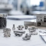
يساعد هذا الشكل في شرح سبب عدم كفاية قيمة لزوجة واحدة. يجب على المهندسين النظر إلى السلوك الريولوجي الكلي: كيف تتغير اللزوجة مع القص، ومدى قوة تفاعل مادة التغذية مع درجة الحرارة، وما إذا كانت الدفعات المختلفة تظل متسقة عبر نطاق القولبة المتوقع.
من الأخطاء الشائعة اعتبار ملء القالب الجيد دليلاً على أن الريولوجيا مقبولة. هذا ضيق جدًا. قد تملأ مادة التغذية جيدًا في تجربة قصيرة خاضعة للرقابة ومع ذلك تسبب تشققًا أو تشوهًا أو تشتتًا أبعاديًا لاحقًا إذا أصبح سلوكها الريولوجي غير مستقر عبر تغيرات درجة الحرارة أو تباين الدفعات أو ظروف القالب الأكثر تعقيدًا.
كيف تتحول مشاكل مادة التغذية إلى عيوب MIM حقيقية
من أكثر الطرق فائدة لفهم مادة التغذية هو التوقف عن معاملتها كخطوة منعزلة. نادرًا ما تبقى مشاكل مادة التغذية داخل مرحلة التغذية. إنها تنتقل إلى المراحل اللاحقة وتغير شكلها. قد يخلق التشتت الضعيف أولاً خللاً في التوازن المحلي للملء، ثم تباينًا في كثافة الجزء الأخضر، ثم تشتتًا في الانكماش، وأخيراً عدم اتساق أبعادي. قد يظهر التحميل العالي جدًا أولاً كضعف في الملء في الأطراف البعيدة، ثم عجز محلي في الكثافة، ثم تشوه في التلبيد. قد يبدو نظام المادة الرابطة غير المتطابق مقبولاً في القولبة، ثم يخلق غازات محصورة، أو فقاعات، أو تشقق، أو تشوهًا مرتبطًا بإزالة المادة الرابطة لاحقًا.

الاستنتاج الأساسي: تظهر معظم مشاكل مادة التغذية لاحقًا، ولهذا السبب يجب أن يتتبع تحليل السبب الجذري العيوب عائدًا عبر سلسلة MIM الكاملة.
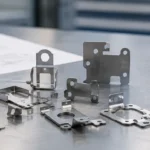
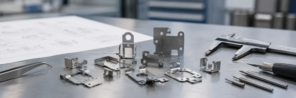
قد لا يظل التشتت الضعيف، أو مادة التغذية المحملة بشكل زائد، أو عدم تطابق المادة الرابطة، أو عدم اتساق الدفعات مرئية كمشاكل مادية. غالبًا ما تظهر لاحقًا كنقص في الملء، أو تباين في الكثافة، أو فقاعات، أو تشقق، أو تشوه، أو انحراف أبعادي. يساعد هذا الشكل المستخدمين على ربط التباين المبكر في مرحلة المادة بعيوب المنتج النهائي.
| مشكلة مادة التغذية | عرض مبكر للعملية | النتيجة النهائية المحتملة |
|---|---|---|
| ضعف تشتت المسحوق والمادة الرابطة | تباين في الملء المحلي أو توزيع غير مستقر للكثافة | تشتت في الانكماش، عدم اتساق أبعادي، مناطق ضعيفة |
| نسبة التحميل الصلب مرتفعة جداً | لزوجة عالية، حساسية للضغط، ملء غير كامل للأجزاء البعيدة | مناطق غير ممتلئة، تشوه، أبعاد غير مستقرة |
| نسبة التحميل الصلب منخفضة جداً | تدفق سهل ولكن حجم مادة رابطة أكبر | انكماش أعلى وتحكم أضعف في الأبعاد |
| نظام المادة الرابطة غير متوافق مع مسار إزالة المادة الرابطة | قد يبدو الجزء الأخضر مقبولاً بعد القولبة | تشقق، تقشر، تشوه أثناء إزالة المادة الرابطة |
| ضعف ثباتية الدفعة من الخلط | نافذة قولبة متغيرة بين الدفعات | انحراف أبعادي من دفعة لأخرى وجودة غير مستقرة |
جدول تشخيص العيوب لمراجعة متعلقة بمادة التغذية
| عيب ملاحظ | سبب محتمل متعلق بمادة التغذية | أسباب أخرى يجب التحقق منها أيضًا |
|---|---|---|
| لقطة قصيرة أو تفاصيل دقيقة غير مكتملة | لزوجة عالية، سلوك تدفق ضعيف، تحميل صلب مفرط، أو خصائص ريولوجية غير مستقرة. | حجم البوابة، التهوية، ضغط الحقن، سرعة الحقن، درجة حرارة القالب، وسمك الجدار المحلي. |
| تشققات بعد إزالة المادة الرابطة | عدم توازن المادة الرابطة، الرطوبة، عدم تجانس المسحوق والمادة الرابطة، أو سلوك غير آمن لإزالة المادة الرابطة. | معدل التسخين، جو إزالة المادة الرابطة، سمك المقطع، انتقال الجدار، ودعم الجزء. |
| انتفاخ أو فراغات داخلية | مشكلة تحكم متطايرة، غاز محتبس، تلوث، أو منطقة غنية بالمادة الرابطة محليًا. | ملف إزالة المادة الرابطة، التهوية، كثافة الجزء الأخضر، وحالة تحميل الفرن. |
| التواء بعد التلبيد | تباين في التحميل الصلب، عدم تطابق الكثافة المحلي، أو تعبئة غير متساوية لمادة التغذية. | دعم التلبيد، هندسة الجزء، توازن سمك الجدار، تصميم المثبت، وملف الفرن. |
| تباين الأبعاد بين الدفعات | تباين مادة التغذية من دفعة لأخرى، انحراف اللزوجة، أو استجابة انكماش غير متسقة. | تعويض القالب، ملف التلبيد، طريقة القياس، واستراتيجية الأبعاد الحرجة. |
| خشونة السطح أو بقع سوداء | مشكلة المسحوق، تلوث، بقايا المادة الرابطة، أو تشتت ضعيف. | سطح القالب، حالة الحقن، اكتمال إزالة المادة الرابطة، جو التلبيد، وعمليات التشغيل الثانوية. |
حدود مهمة: ليس كل عيب في MIM ناتجًا عن مادة التغذية. تصميم القالب، معلمات الحقن، ملف إزالة المادة الرابطة، دعم التلبيد، اختيار المواد، وطريقة الفحص يمكن أن تخلق أعراضًا متشابهة. يجب أن تكون مادة التغذية جزءًا من تحليل السبب الجذري، وليس التفسير الوحيد.
للتشخيص الأوسع، اربط هذه المراجعة بـ قائمة مراجعة مراقبة الجودة لـ MIM, قدرات الفحص والاختبار لـ MIM, ، و تخطيط تفاوتات MIM.
ما الذي يجب أن يتحقق منه قسم ضمان الجودة قبل الموافقة على مادة تغذية للإنتاج
لا ينبغي لقسم ضمان الجودة تقييم مادة التغذية فقط بناءً على ما إذا كان يمكن تشكيلها في جزء مرئي. يجب أن يشمل الموافقة الحقيقية اتساق المواد، وسلوك العملية، والأدلة المستمدة من الاستجابة اللاحقة. بالنسبة للمشاريع التي تستخدم حبيبات مادة تغذية مزودة من الخارج، يجب أن تشمل المراجعة معلومات الاتساق المقدمة من المورد حيثما كانت متاحة، بالإضافة إلى التحقق الداخلي من خلال الاستجابة للقولبة، وإزالة المادة الرابطة، والتلبيد، والفحص البعدي. هذا يتجنب الإيحاء بأن صيغة مادة التغذية مقبولة لمجرد أن العينات الأولى المقولبة تبدو كاملة.
من المفيد أيضًا فصل بيانات إصدار مادة التغذية عن أدلة الجاهزية الحقيقية للإنتاج. غالبًا ما تتضمن المراجعة الكاملة تقنيًا ليس فقط نتائج الاختبار من مادة التغذية نفسها، ولكن أيضًا أدلة عملية لاحقة: ما إذا كانت الدفعة تزيل المادة الرابطة بأمان، وما إذا كان الانكماش يظل ثابتًا، وما إذا كانت أبعاد الجزء الحرجة تظل ضمن نافذة التحكم المقصودة. بالنسبة للسياق المعياري وطرق الاختبار، فإن موارد معايير MPIF توفر نقطة مرجعية مفيدة لمناقشات المواد والاختبار في علم المساحيق المعدنية والقولبة بالحقن المعدني (MIM).
| نقطة فحص ضمان الجودة | سبب الأهمية | المخاطر في حال تجاهلها |
|---|---|---|
| مراجعة كيمياء المسحوق والتلوث | يؤكد أن نظام المسحوق يطابق المخاطر المقصودة للسبيكة والتطبيق. | تآكل غير متوقع، سلوك مغناطيسي، مشكلة قوة، عيب سطحي، أو استجابة تلبيد غير طبيعية. |
| اتساق حجم الجسيمات وشكلها | يؤثر على التعبئة، التدفق، طلب المادة الرابطة، نشاط التلبيد، والحالة السطحية. | تشتت الأبعاد، سطح خشن، انكماش غير مستقر، أو عدم اتساق الكثافة. |
| توحيد حبيبات المادة وحالة الدفعة | يساعد في اكتشاف تباين الخلط أو التحبيب قبل القولبة. | سلوك حقن غير مستقر، تعبئة جزئية محلية، أو انحراف العملية من دفعة إلى أخرى. |
| سلوك الريولوجيا | يوضح ما إذا كانت مادة التغذية لديها نافذة قولبة قابلة للاستخدام. | طلقات قصيرة، تعبئة حساسة للضغط، خطوط لحام، أو تكرار غير مستقر للميزات الدقيقة. |
| التحكم في الرطوبة أو المواد المتطايرة | يقلل من المخاطر المتعلقة بالغازات أثناء القولبة وإزالة المادة الرابطة. | فقاعات، فراغات، تشققات، بثور، أو علامات سطحية. |
| اتساق الجزء الأخضر | يربط جودة مادة التغذية باستقرار الجزء المصبوب الفعلي. | تنوع الكثافة المخفي، وتلف المناولة، وعدم اتساق الانكماش لاحقًا. |
| استجابة مبكرة لإزالة المادة الرابطة والتلبيد | يؤكد ما إذا كانت مادة التغذية يمكنها تحمل مسار العملية الكامل. | تشقق في مرحلة متأخرة، تشوه، انحراف الأبعاد، وتأخر الإجراء التصحيحي. |
ما يغفل عنه المصممون والمشترون غالبًا بشأن مادة التغذية
غالبًا ما يركز المصممون على الهندسة ويفترضون أن مادة التغذية هي مشكلة مواد يمكن حلها لاحقًا. غالبًا ما يقارن المشترون قرارات مادة التغذية بشكل أساسي حسب التكلفة لكل كيلوغرام. كلا الرأيين غير مكتملين. تتغير حساسية مادة التغذية مع الهندسة. الميزات الطويلة التدفق، والانتقالات غير المتساوية في سمك الجدار، وتركيز الكتلة المحلي، والأبعاد الحرجة الحساسة للكثافة تزيد جميعها من أهمية تصميم مادة التغذية. في الوقت نفسه، ليست مادة التغذية الأقل تكلفة دائمًا هي الخيار الأقل خطورة للإنتاج إذا كانت تخلق نافذة تشكيل ضيقة، أو استجابة غير مستقرة لإزالة المادة الرابطة، أو معدلات رفض أعلى لاحقًا.
لهذا السبب يجب مراجعة مادة التغذية جنبًا إلى جنب مع التصميم، والأدوات، وإزالة المادة الرابطة، والتلبيد، والفحص. إذا كان فريقك يقرر ما إذا كان الجزء مناسبًا تمامًا لتقنية MIM من البداية، فإن هذا القسم يتناسب جيدًا مع إرشادات تصميم MIM صفحة دليل تفاوتات MIM.
ما يجب تقديمه لمراجعة هندسية متعلقة بمادة التغذية
عندما يواجه مشروع ما مشاكل مثل عدم اكتمال الحقن (short shots)، أو التشقق، أو التشوه، أو الأبعاد غير المستقرة، أو عيوب السطح غير المبررة، فلا ينبغي أن تبدأ المراجعة بطلب سعر بسيط. تتطلب مراجعة MIM المفيدة الرسم، والمادة، والأبعاد، وأهداف التفاوت، وظروف التطبيق، والخلفية الإنتاجية. هذا يسمح للفريق الهندسي بالحكم على ما إذا كانت المشكلة مرتبطة على الأرجح بمادة التغذية، أو الهندسة، أو الأدوات، أو القولبة بالحقن، أو إزالة المادة الرابطة، أو التلبيد، أو استراتيجية الفحص.
| المعلومات المطلوب تقديمها | لماذا تساعد المراجعة |
|---|---|
| رسم ثنائي الأبعاد وملف CAD ثلاثي الأبعاد | تسمح بمراجعة سمك الجدار، ومناطق التدفق الطويل، والأبعاد الحرجة، والأضلاع، والثقوب، والأخاديد، وتركيز الكتلة المحلي. |
| متطلبات المواد | يربط اختيار السبيكة بسلوك المسحوق، واستجابة التلبيد، ومتطلبات مقاومة التآكل، والقوة، أو الخصائص المغناطيسية، أو مقاومة التآكل. |
| الأبعاد الحرجة والتفاوتات | يساعد في تحديد الأماكن التي يكون فيها التحكم في الانكماش وتكرار الأبعاد أكثر أهمية. |
| متطلبات السطح والتجميلية | يساعد في الحكم على مخاطر المسحوق، والقولبة، وإزالة المادة الرابطة، والتلبيد، والعمليات الثانوية. |
| الحجم السنوي المقدر | يدعم مراجعة ملاءمة العملية، واستثمار الأدوات، وتخطيط الإنتاج، وهيكل التكلفة. |
| معلومات العيوب الحالية، إن وجدت | يسمح بمراجعة السبب الجذري للطلقات القصيرة، والتشققات، والفراغات، والالتواء، وعيوب السطح، أو الانحرافات الأبعاد. |
| بيئة التطبيق | يوضح ما إذا كان يجب إعطاء الأولوية للتآكل، أو الحمل، أو التآكل، أو الاستجابة المغناطيسية، أو درجة الحرارة، أو ملاءمة التجميع. |
طلب مراجعة مخاطر جودة MIM المتعلقة بمادة التغذية
أرسل رسمك ثنائي الأبعاد، وملف CAD ثلاثي الأبعاد، ومتطلبات المواد، والأبعاد الحرجة، واحتياجات التفاوت، ومتطلبات السطح، والحجم السنوي المقدر، وخلفية التطبيق، وأي معلومات عيوب موجودة. يمكن لـ XTMIM مراجعة ما إذا كانت مخاطر الجودة مرتبطة بشكل أكبر بسلوك مادة التغذية، أو ملء القالب، أو إزالة المادة الرابطة، أو انكماش التلبيد، أو الهندسة، أو استراتيجية الفحص قبل اتخاذ قرارات الأدوات، أو الإنتاج التجريبي، أو زيادة الإنتاج.
المعايير والمراجع الفنية
تستخدم هذه المقالة مراجع خارجية فقط حيث تدعم الموضوع الهندسي. الـ نظرة عامة على عملية MIMA مفيد لفهم مسار مادة تغذية MIM، والقولبة، وإزالة المادة الرابطة، والتلبيد. الـ نظرة عامة على MIM من EPMA يوفر سياقًا إضافيًا حول أنظمة المسحوق والمادة الرابطة ومعالجة MIM. الـ موارد معايير MPIF يمكن أن يدعم مناقشات المواد والاختبار، ولكن يجب دائمًا تأكيد معايير القبول الخاصة بالمشروع مقابل الرسومات، ومتطلبات المواد، وخطط الفحص، وقدرة عملية المورد.
الخلاصة الهندسية النهائية
في تقنية MIM، لا تقتصر جودة مادة التغذية على جعل المسحوق المعدني يتدفق فحسب. بل تتعلق بإنشاء جسر مستقر بين خصائص المسحوق، وتصميم المادة الرابطة، وجودة الخلط، والريولوجيا، وسلسلة العمليات اللاحقة بأكملها. عندما تكون مادة التغذية مصممة بشكل جيد ومضبوطة بشكل جيد، يصبح القولبة أكثر استقرارًا، وتصبح إزالة المادة الرابطة أكثر أمانًا، ويصبح انكماش التلبيد أكثر قابلية للتنبؤ، وتصبح جودة الجزء النهائي أسهل في الحفاظ عليها. عندما تكون مراقبة مادة التغذية ضعيفة، تقضي العمليات اللاحقة وقتها في تعويض التباين الذي كان ينبغي ألا يدخل النظام من الأساس.
الخلاصة: إذا كنت ترغب في الحصول على جودة MIM مستقرة، فلا تتعامل مع مادة التغذية كتفصيل صغير في المراحل المبكرة. إنها واحدة من القرارات الأساسية للعملية التي تحدد ما إذا كانت سلسلة جودة الجزء بأكملها ستبقى مستقرة أم ستصبح تفاعلية.
ملاحظة مراجعة هندسية: تم إعداد هذه المقالة لتقييم مشاريع MIM بين الشركات (B2B)، بما في ذلك جدوى التصميم، ومخاطر الجودة المتعلقة بمادة التغذية، واستقرار إزالة المادة الرابطة والتلبيد، والتكرارية الأبعاد، ومراجعة التصنيع المستندة إلى الرسومات. يجب تأكيد الاستنتاجات الخاصة بالمشروع مع الرسومات الفعلية، ومتطلبات المواد، والتفاوتات، واحتياجات الفحص، وحجم الإنتاج.
الأسئلة الشائعة
هل تؤثر جودة مادة التغذية حقًا على جزء MIM النهائي بهذا القدر؟
نعم. تؤثر جودة مادة التغذية على استقرار القولبة، وقوة الجزء الأخضر، وسلوك إزالة المادة الرابطة، واتساق انكماش التلبيد، وتوزيع الكثافة، وقابلية تكرار الأبعاد النهائية. العديد من العيوب في المراحل المتأخرة تبدأ من تباين مبكر في مادة التغذية.
هل تحميل المواد الصلبة الأعلى دائمًا أفضل في مادة تغذية MIM؟
لا يمكن أن يؤدي التحميل الصلب الأعلى إلى تقليل الانكماش وحجم المادة الرابطة، ولكنه يزيد أيضًا من اللزوجة ويضيق نافذة القولبة. أفضل قيمة إنتاجية هي عادةً نافذة تشغيل مستقرة، وليست أعلى نسبة تحميل ممكنة.
لماذا يمكن لمادة التغذية أن تُشكّل قالبًا جيدًا ولكنها تفشل لاحقًا؟
الملء الجيد لا يعني تلقائيًا إزالة آمنة للمادة الرابطة أو تلبيدًا مستقرًا. قد تمتلئ مادة التغذية (feedstock) بشكل نظيف ومع ذلك تتسبب في حدوث تشقق، أو انتفاخ، أو التواء، أو انحراف في الأبعاد إذا لم يتم موازنة نظام المادة الرابطة، أو التحميل الصلب، أو الريولوجيا لسلسلة العملية بأكملها.
ما هي مشاكل مادة التغذية التي يمكن أن تسبب عيوبًا في أجزاء MIM؟
تشمل المخاطر الشائعة المتعلقة بمواد التغذية MIM ضعف تشتت المسحوق والمادة الرابطة، وعدم استقرار التحميل الصلب، والرطوبة الزائدة، والتلوث، واللزوجة العالية، وعدم توافق المادة الرابطة، والاختلاف من دفعة لأخرى. قد تظهر هذه المشكلات لاحقًا على شكل شورت شوت (نقص في الملء)، أو تشققات، أو فراغات، أو عيوب سطحية، أو التواء، أو تباين في الأبعاد.
ما الذي يجب أن تفحصه مراقبة الجودة قبل إطلاق دفعة من مادة التغذية؟
يجب أن تقوم مراقبة الجودة (QA) بمراجعة اتساق المسحوق، وخطر التلوث، وتجانس الحبيبات، وسلوك الريولوجيا، والتحكم في الرطوبة أو المواد المتطايرة، وإمكانية تتبع الدُفعات. كما يجب عليها التحقق من الأدلة اللاحقة مثل اتساق كثافة الجزء الأخضر، وقابلية تكرار عملية القولبة، واستقرار الانكماش، وإشارات التشوه المبكرة.
ما هي المعلومات التي يجب على المشترين تقديمها لمراجعة المواد الخام المتعلقة بـ MIM؟
يجب على المشترين تقديم رسم ثنائي الأبعاد (2D)، ملف تصميم ثلاثي الأبعاد (3D CAD)، متطلبات المواد، الأبعاد الحرجة، احتياجات التفاوت، متطلبات السطح، الحجم السنوي المقدر، بيئة التطبيق، وأي معلومات عن العيوب الموجودة. يساعد هذا فريق الهندسة على مراجعة ما إذا كانت استراتيجية مادة التغذية (feedstock)، أو الهندسة، أو القولبة، أو إزالة المادة الرابطة (debinding)، أو التلبيد (sintering)، أو الفحص قد تكون هي المحرك الرئيسي للمخاطر.