Demander un devis de moulage par injection de métal
Partagez votre dessin, vos exigences de matériau, votre volume annuel, vos besoins de tolérance ou les détails de votre application. Notre équipe d'ingénierie examinera votre projet MIM et répondra avec un retour technique ou un devis.
Quelles industries utilisent le moulage par injection de métal ?
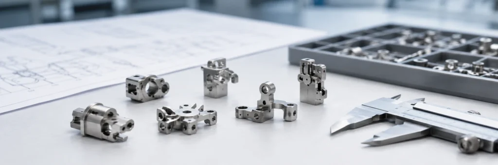
Le moulage par injection de métal est utilisé dans les industries qui nécessitent de petites pièces métalliques répétables dont la géométrie est difficile, lente ou coûteuse à usiner. Les industries typiques du MIM comprennent les dispositifs médicaux et dentaires, les composants automobiles, l'électronique, les appareils portables, les serrures, les outils industriels, les montres, les lunettes, le matériel grand public et certaines assemblages liés à l'aérospatiale. Cet article explique les applications industrielles et l'adéquation des pièces ; il ne s'agit pas d'une prévision de la taille du marché ou d'un rapport général sur le marché du MIM. Le MIM n'est pas choisi uniquement parce qu'une pièce semble complexe. Il devient pratique lorsque la taille de la pièce, le matériau, le volume annuel, le plan de tolérance et les opérations secondaires correspondent à la fenêtre de processus.
Le moulage par injection de métal est utilisé dans les industries qui nécessitent de petites pièces métalliques répétables dont la géométrie est difficile, lente ou coûteuse à usiner. Les pièces MIM typiques industries MIM comprennent les dispositifs médicaux et dentaires, les composants automobiles, l'électronique, les appareils portables, les serrures, les outils industriels, les montres, les lunettes, le matériel grand public et certaines assemblages liés à l'aérospatiale. Cet article explique les applications industrielles et l'adéquation des pièces ; il ne s'agit pas d'une prévision de la taille du marché ou d'un rapport général sur le marché du MIM. Le MIM n'est pas choisi uniquement parce qu'une pièce semble complexe. Il devient pratique lorsque la taille de la pièce, le matériau, le volume annuel, le plan de tolérance et les opérations secondaires correspondent à la fenêtre de processus. Les applications les plus solides applications de moulage par injection de métal sont les petites pièces MIM avec des caractéristiques fines, des formes internes, des bossages, des fentes, des mécanismes miniatures ou des alliages difficiles à usiner. Les applications faibles sont les grandes pièces, les pièces longues et plates, les sections très épaisses, les surfaces à aspect cosmétique miroir, ou les dimensions critiques de référence qui ne peuvent pas tolérer la variation du retrait de frittage. Pour une bonne décision de fabrication, les ingénieurs doivent évaluer les matériaux MIM, les tolérances MIM, le coût de l'outillage, le risque de déliantage, le retrait de frittage, la densité, l'état de surface et l'usinage post-frittage avant d'approuver le processus ou de soumettre un dessin pour examen.
Le MIM est couramment utilisé pour les petites pièces métalliques reproductibles dans les applications médicales, automobiles, électroniques, industrielles et les wearables.
Pourquoi différentes industries utilisent le moulage par injection de métal
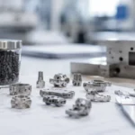
Différentes industries utilisent le moulage par injection de métal lorsqu'une petite pièce métallique a une demande répétée suffisante, une complexité géométrique et une exigence de matériau pour justifier l'outillage et le contrôle du frittage. Le processus comprend généralement la sélection de la poudre métallique, la préparation du système de liant, le mélange du feedstock, le moulage par injection, le déliantage, le frittage et les opérations secondaires si nécessaire. La principale valeur d'ingénierie n'est pas simplement la “ forme complexe ”. C'est la capacité de consolider des caractéristiques fines, des formes internes, des bossages, des fentes, des dents, des charnières ou des mécanismes compacts dans une pièce répétable de forme quasi nette tout en réduisant l'usinage inutile sur les surfaces non critiques.
ASTM B883 est pertinent lorsque des matériaux MIM ferreux sont spécifiés car il définit la voie générale des matériaux pour les pièces ferreuses moulées par injection de métal, y compris le mélange de poudre et de liant, l'injection, le déliantage, le frittage et un éventuel traitement thermique. La norme MPIF 35-MIM est pertinent car il aide les ingénieurs et les acheteurs à spécifier les matériaux MIM avec des attentes plus cohérentes. Ces normes sont importantes lors de la cotation, de la révision des dessins, de l'approbation des matériaux, des essais mécaniques et de l'acceptation de la production.
Pour l'évaluation technique, la vraie question n'est pas seulement “ quelles industries utilisent des pièces MIM ”. La meilleure question est : “ Quelles industries ont de petites pièces métalliques où la géométrie MIM, les performances du matériau, le coût de l'outillage, le contrôle du frittage et le post-traitement ont du sens ensemble ? ” Les références industrielles telles que le Metal Injection Molding Association et European Powder Metallurgy Association décrivent le MIM comme un processus utilisé sur plusieurs marchés industriels, mais la sélection finale du processus dépend toujours des exigences de la géométrie de la pièce et de la qualification. Pour une lecture orientée marché, utilisez le guide des tendances de l'industrie MIM; ; pour la faisabilité au niveau de la pièce, utilisez le Guide de sélection des applications MIM.
Demande industrielle vs Adéquation des pièces MIM
Une croissance du marché MIM ou une forte demande industrielle ne signifie pas que chaque pièce métallique de cette industrie devrait utiliser le MIM. Les termes du marché tels que applications médicales MIM, pièces automobiles MIM, composants électroniques MIM, ou pièces MIM pour appareils portables montrent où le processus est souvent envisagé. La décision de fabrication doit toujours être prise au niveau de la pièce : la géométrie, l'épaisseur de paroi, le volume annuel, la nuance du matériau, la stratégie de tolérance, le risque de déliantage, le retrait de frittage, l'état de surface et la méthode d'inspection doivent tous s'articuler ensemble.
Signal de recherche ou d'entreprise
Ce que cela vous indique
Ce que cela ne prouve pas
Meilleure étape suivante
Croissance du marché MIM
De plus en plus d'industries envisagent le MIM pour les composants métalliques compacts
Cela ne prouve pas qu'une pièce spécifique est moulable ou économique
Examiner la géométrie de la pièce, le volume annuel et la voie d'approvisionnement des matériaux
Exemples d'applications industrielles
Des produits similaires utilisent peut-être déjà le MIM avec succès
Ils ne remplacent pas une revue DFM spécifique au dessin
La qualité des pièces MIM dépend du contrôle du feedstock, de la stabilité du moulage, du déliantage, du retrait de frittage, de la densité et du traitement secondaire.
Secteurs utilisant couramment des pièces MIM
Les secteurs ci-dessous doivent être considérés comme des catégories d'applications, et non comme un classement de parts de marché. Chaque secteur utilise le MIM pour des raisons différentes : les projets médicaux peuvent privilégier la résistance à la corrosion et la facilité de nettoyage ; les projets automobiles peuvent privilégier la résistance à l'usure, à la fatigue et la stabilité des lots ; les projets électroniques et d'appareils portables peuvent privilégier la miniaturisation, l'ajustement à l'assemblage et le traitement de surface. Si vous avez besoin d'une page de navigation plus générale par secteur, consultez la Centre des industries MIM. Si vous avez besoin d'exemples au niveau de la pièce, consultez le applications de moulage par injection de métal page.
Dispositifs médicaux et dentaires
Les applications médicales et dentaires utilisent souvent le MIM pour de petits composants en acier inoxydable, en alliage de titane ou en alliage spécifique, où la géométrie, la résistance à la corrosion, la répétabilité et l'état de surface validé sont importants. Les exemples typiques incluent des composants d'instruments chirurgicaux, des brackets orthodontiques, de petites mâchoires, des pièces d'outils dentaires, du matériel endoscopique, des éléments de préhension et des boîtiers compacts.
Le MIM peut être utile dans ce domaine car de nombreuses pièces médicales sont petites, détaillées et difficiles à usiner économiquement en volume. Cependant, les pièces MIM médicales nécessitent un contrôle plus strict que le matériel industriel général. Les ingénieurs doivent examiner la certification des matériaux, les exigences de biocompatibilité, la passivation, le nettoyage, les limites de bavures, la rugosité de surface, la traçabilité des lots et la méthode d'inspection avant d'approuver la production.
Une erreur d'ingénierie courante consiste à supposer qu'une pièce MIM médicale peut sortir directement du frittage avec toutes les surfaces fonctionnelles finies. Dans un scénario de domaine composite pour la formation en ingénierie, une mâchoire d'instrument médical a été initialement conçue comme un composant MIM entièrement moulé, mais la surface de préhension ne répondait pas au comportement de contact et à la définition d'arête requis. Le vrai problème n'était pas seulement la rugosité de surface ; la conception mélangeait une géométrie quasi nette avec des références fonctionnelles de précision. La correction a consisté à conserver le corps comme une pièce MIM quasi nette tout en ajoutant un usinage post-frittage sur la surface de préhension et la référence fonctionnelle. Pour éviter la récurrence, les projets médicaux doivent séparer la géométrie moulée, les surfaces de contact usinées, les zones polies, les surfaces passivées et les références contrôlées par inspection avant l'outillage.
Composants automobiles et de mobilité
Les applications automobiles utilisent le MIM lorsque de petites pièces métalliques nécessitent un volume de production stable et une géométrie fonctionnelle répétable. Les pièces MIM typiques peuvent inclure des composants d'actionneurs, du matériel lié aux capteurs, de petits supports, des éléments de verrouillage, des pièces de mécanismes de siège, de petits composants liés à la transmission, du matériel pour véhicules électriques et des pièces d'usure compactes.
La raison pour laquelle les projets automobiles envisagent le MIM est généralement une combinaison de consolidation de géométrie, d'usinage réduit, de résistance à l'usure, de lots cohérents et de contrôle des coûts en volume. Pour les pièces MIM automobiles, les principaux points de contrôle sont le contrôle du retrait de frittage, la densité, la porosité, la réponse au traitement thermique, le comportement à la fatigue, la stabilité dimensionnelle et le calibrage fonctionnel.
Les projets automobiles montrent également pourquoi les directives de conception MIM doivent être examinées avant de transférer une conception usinée dans un moule. Dans un scénario de domaine composite pour la formation en ingénierie, un petit support automobile avait une qualité de pièce verte acceptable mais a échoué à la planéité finale après frittage. La pièce avait un bossage épais relié à un long bras mince, de sorte que les deux zones ont rétréci et refroidi différemment. La cause systémique était que la conception CNC avait été transférée au MIM sans repenser la transition de paroi, le support de frittage, la position du point d'injection et l'orientation de la pièce. La correction a consisté à lisser la transition du bossage, à changer le support de cuisson et à déplacer la zone critique de planéité loin de la zone à plus haut risque de retrait. Avant de soumettre un devis pour des pièces MIM automobiles, l'équilibre des parois, le support de frittage, l'emplacement du point d'injection et un éventuel calibrage ou usinage doivent être examinés ensemble.
Électronique, connecteurs et dispositifs portables
Les produits électroniques et les wearables utilisent souvent le MIM pour les charnières, les boutons, les petits cadres structurels, les pièces liées aux connecteurs, les composants de blindage, les boîtiers de capteurs, les pièces de verrouillage, le matériel lié aux caméras, les pièces de montres connectées et les interfaces mécaniques compactes.
Ces pièces combinent souvent une petite taille, un ajustement d'assemblage, des caractéristiques fines et des surfaces cosmétiques ou semi-cosmétiques. Le MIM peut supporter des géométries détaillées, mais les projets électroniques sous-estiment souvent le risque lié au traitement de surface. Le polissage, le PVD, le placage, le grenaillage et la passivation peuvent révéler des pores, des marques d'écoulement, des lignes de joint, des lignes de soudure ou des distorsions de frittage.
Pour les pièces électroniques visibles, le dessin et le plan qualité doivent définir les surfaces cosmétiques, les surfaces non cosmétiques, la zone de porte, la surépaisseur de polissage, les piqûres acceptables, les limites d'arrondi des bords, l'éclairage d'inspection, et si le PVD ou le placage est décoratif, protecteur ou fonctionnel. Dans un scénario composite de terrain pour la formation en ingénierie, une charnière de dispositif portable semblait acceptable après frittage et polissage, mais après revêtement PVD, de petites piqûres et des points sombres sont devenus visibles. L'étape de polissage avait ouvert des pores proches de la surface, et le revêtement PVD les a rendus plus faciles à voir sous lumière réfléchie. La cause systémique était que l'équipe avait approuvé la pièce MIM principalement sur les dimensions et n'avait pas défini les zones cosmétiques, l'acceptation des pores, la surépaisseur de polissage ou l'inspection avant PVD. L'action corrective a été d'ajuster le contrôle de densité, de modifier les étapes de polissage et d'inspecter avant revêtement. Pour les projets futurs, la voie de revêtement et l'inspection cosmétique doivent faire partie de la revue de sortie d'outillage, et non une réflexion après coup.
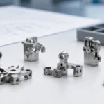
Serrurerie, Quincaillerie de Sécurité et Quincaillerie Mécanique
Les industries de la serrurerie et de la quincaillerie mécanique utilisent le MIM pour les cames, les cliquets, les leviers, les loquets, les boutons, les liaisons internes, les petits engrenages, les blocs coulissants et les pièces mécaniques compactes à faces fonctionnelles multiples.
Le MIM est souvent envisagé car les pièces de serrure peuvent nécessiter des profils complexes, une résistance à l'usure locale, de petites caractéristiques et un ajustement d'assemblage stable. Les aciers faiblement alliés, les aciers inoxydables et les nuances d'acier inoxydable trempable peuvent être sélectionnés en fonction de la résistance, de la résistance à la corrosion, de l'usure par glissement et des exigences de dureté de surface.
Un composant de serrure peut passer l'inspection dimensionnelle mais échouer lors des tests de cycle si la dureté du matériau, la densité, l'état de surface, la géométrie des bords, la lubrification ou le traitement thermique ne sont pas adaptés. Dans un scénario composite de terrain pour la formation en ingénierie, une came de serrure avait des dimensions correctes mais présentait une usure précoce lors du cyclage. Le matériau inoxydable sélectionné avait une résistance à la corrosion acceptable mais une dureté de surface insuffisante pour un contact de glissement répété. La cause réelle était une sélection de matériau basée sur l'apparence et la résistance à la corrosion plutôt que sur la contrainte de contact et le mécanisme d'usure. La correction a été de passer à une nuance trempable et de vérifier la dureté après traitement thermique. Pour les serrures et la quincaillerie mécanique, le transfert de couple, le contact glissant, la lubrification, la dureté, l'état des bords et les tests d'usure doivent être examinés avant l'approbation finale du matériau MIM.
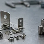
Outils Industriels, Outils Électroportatifs et Pièces d'Équipement
Les outils industriels et les équipements peuvent utiliser le MIM pour les petits leviers, les supports, les pièces d'entraînement, les composants d'usure, les pièces de réglage, les composants d'outils miniatures, les pièces liées aux pompes, les petites pièces liées aux vannes et les pièces à faces multiples usinées.
La question technique clé est de savoir si la pièce nécessite principalement de la résistance, de la dureté de surface, de la résistance à l'usure, de la ténacité, de la résistance à la corrosion, un comportement magnétique ou une répétabilité dimensionnelle. Par exemple, le 17-4PH peut convenir lorsque la résistance et la résistance à la corrosion sont toutes deux nécessaires. L'acier faiblement allié peut être plus approprié lorsque la réponse au traitement thermique et la résistance à l'usure importent plus que la résistance à la corrosion.
Les pièces industrielles nécessitent également un plan d'inspection pratique. Un dessin comportant de nombreuses tolérances serrées peut imposer un usinage secondaire inutile et augmenter les coûts. Lors de la revue de conception, le fournisseur doit séparer les dimensions moulées, les dimensions de calibrage, les dimensions usinées et les dimensions des jauges fonctionnelles.
Assemblages aéronautiques et à hautes spécifications
Les assemblages aéronautiques peuvent utiliser le MIM pour certaines petites pièces où la géométrie, le contrôle du poids et la répétabilité sont importants. Les applications possibles incluent les petits supports, les boîtiers de capteurs, les composants d'actionneurs, les éléments de fixation, la quincaillerie secondaire et les pièces mécaniques compactes.
Ces projets nécessitent une évaluation prudente. La décision doit commencer par la norme de matériau, la densité, la microstructure, les essais mécaniques, la traçabilité, le traitement thermique, l'état de surface et le processus d'approbation. Le MIM ne doit pas être présenté comme un remplacement rapide des pièces aéronautiques critiques sans qualification appropriée.
Pour les assemblages à hautes spécifications, la question n'est pas “ la forme peut-elle être moulée ? ” La vraie question est de savoir si le fournisseur peut prouver les performances du matériau, la stabilité dimensionnelle, la constance des lots, la répétabilité des inspections et le contrôle à long terme du processus.
Montres, lunetterie, bijouterie et produits lifestyle
Les montres, les lunettes, les produits de type bijouterie et la quincaillerie lifestyle peuvent utiliser le MIM pour les boîtiers, les charnières, les boucles, les montures, les composants décoratifs, les boîtiers portables et les pièces mécaniques miniatures.
Ces produits nécessitent souvent une géométrie attrayante et un bon état de surface. Le MIM peut créer des pièces métalliques de forme quasi nette, mais la surface brute de frittage n'est pas automatiquement prête pour le polissage miroir, le PVD ou l'électroplacage. Les pores, les lignes de joint, les marques de point d'injection et les ondulations de polissage peuvent devenir visibles après la finition.
Si une pièce a une surface visible de classe A, le plan d'outillage doit définir l'emplacement du point d'injection, la direction de la ligne de joint, la surépaisseur de polissage, l'objectif de rugosité de surface, la protection des arêtes, le support de frittage, l'acceptation des pores et les critères d'inspection cosmétique finale avant la libération de l'outillage.
Produits de consommation et composants de petits appareils électroménagers
Les produits de consommation utilisent le MIM pour les loquets, boutons, charnières, pièces de verrouillage, composants d'appareils de soins personnels, mécanismes de petits appareils électroménagers, quincaillerie de cuisine, supports compacts et petites pièces structurelles nécessitant la résistance du métal dans une production répétable.
La raison d'utiliser le MIM dans les biens de consommation est généralement la combinaison du volume de production, de la consolidation des pièces et de la réduction de l'usinage. Si le volume annuel est faible, ou si la pièce est suffisamment simple pour l'emboutissage, le moulage sous pression, le tournage CNC ou le moulage en alliage de zinc, le MIM peut ne pas être le meilleur choix économique.
Pour les produits de consommation, l'équipe de projet doit vérifier non seulement le prix unitaire, mais aussi le coût de l'outillage, le risque de rejet esthétique, la tolérance d'assemblage, le rendement du placage ou du revêtement, la protection de l'emballage et la cohérence des lots à long terme.
Tableau d'adéquation sectorielle pour les pièces MIM
Pores de polissage, porosités, lignes de joint visibles
Produits de consommation
Loquets, boutons, mécanismes, petites équerres
Répétabilité en grands volumes et consolidation de pièces
Amortissement de l'outillage, tolérance d'assemblage, rendement de revêtement
Le MIM est généralement envisagé lorsque de petites pièces métalliques complexes nécessitent des volumes de production répétables et un usinage réduit.
MIM vs CNC vs PM : Quel procédé correspond le mieux aux besoins de l'industrie ?
Procédé
Meilleur ajustement
Points forts
Limites
Quand ne pas utiliser
Moulage par injection de métal
Pièces MIM petites et complexes en volume moyen à élevé
Géométrie multi-caractéristiques, options de matériaux, usinage réduit sur les zones non critiques
Coût d'outillage, retrait de frittage, risque de déliantage, contrôle de la distorsion
Très faible volume, grandes pièces, planéité extrême, contrôle ultra-précis des références
Usinage CNC
Faible volume, prototypes, caractéristiques critiques avec références serrées
Choix flexible des matériaux, références précises, modifications rapides de conception
Coût plus élevé pour les petites pièces complexes répétées
Pièces en grand volume avec de nombreuses caractéristiques 3D répétées
PM conventionnel
Formes simples pressées en volumes de production
Efficace pour les formes à compactage axial
Fonctionnalités latérales, contre-dépouilles et géométrie 3D complexes limitées
Pièces miniatures avec caractéristiques multidirectionnelles complexes
Moulage sous pression
Pièces en alliage de zinc ou d'aluminium en grands volumes
Temps de cycle rapide et bonne capacité de forme pour les alliages non ferreux
Limitations de matériaux, risque de porosité, profil de résistance différent
Acier inoxydable, pièces ferreuses trempables, pièces en alliage haute densité
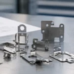
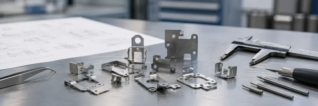
Emboutissage
Pièces en tôle mince
Coût unitaire faible à grande échelle pour les pièces en tôle plates ou formées
Épaisseur 3D limitée et géométrie de bossage local
Pièces 3D épaisses, caractéristiques internes, mécanismes métalliques compacts
Matériaux MIM par secteur
Les matériaux MIM doivent être sélectionnés en fonction des exigences réelles de service, et non uniquement du nom du secteur. Un même secteur peut utiliser du 316L, du 17-4PH, de l'acier inoxydable 420, de l'acier faiblement allié, de l'alliage de titane, de l'alliage de tungstène ou d'autres matériaux selon les besoins en résistance à la corrosion, résistance mécanique, dureté, comportement magnétique, résistance à l'usure, densité, polissage et revêtement.
Le La norme MPIF 35-MIM édition 2025 est une référence utile lorsque les concepteurs et les acheteurs ont besoin d'un langage commun pour les exigences relatives aux matériaux MIM. Elle ne supprime pas la nécessité de tests spécifiques au projet, mais elle permet d'éviter des descriptions de matériaux vagues lors de la demande de devis, de l'échantillonnage et du lancement de la production.
Groupe de matériaux
Utilisation courante par secteur
Pourquoi il est sélectionné
Notes d'ingénierie
Acier inoxydable 316L
Médical, dentaire, montres, électronique, quincaillerie de contact alimentaire
Résistance à la corrosion et aptitude à la finition
Pas idéal pour une usure élevée ou une dureté élevée, sauf si un traitement de surface ou des modifications de conception sont utilisés
Résistance après durcissement par précipitation et résistance modérée à la corrosion
Le traitement thermique peut modifier les dimensions et augmenter le risque de déformation
Acier inoxydable 420
Pièces d'usure, pièces de serrure, pièces d'outillage, petits arbres
Trempabilité et résistance à l'usure
La résistance à la corrosion est inférieure à celle du 316L ; le contrôle du traitement thermique est important
Acier inoxydable 430
Pièces magnétiques, électronique, matériel lié aux capteurs
Comportement magnétique et résistance à la corrosion de l'acier inoxydable
Les exigences magnétiques et mécaniques doivent être vérifiées par des essais sur échantillons
Acier faiblement allié
Automobile, outils, mécanismes de serrure, pièces industrielles
Résistance, résistance à l'usure, réponse au traitement thermique
Nécessite généralement un revêtement, une huilage, un placage ou une protection contre la corrosion si la rouille est un problème
Alliage de titane
Médical, portable, certains matériels aérospatiaux sélectionnés
Faible densité, résistance à la corrosion, potentiel de biocompatibilité
Coût plus élevé des matériaux et de la transformation ; un contrôle de processus plus strict est nécessaire
Alliage de tungstène
Contrepoids, contrôle des vibrations, pièces pilotées par la densité
Haute densité dans un volume compact
Les pièces lourdes nécessitent une attention particulière au déliantage, au frittage et à la distorsion
Quand une industrie ne devrait pas utiliser le MIM
Le MIM n'est pas le bon procédé simplement parce que la pièce est métallique et complexe. Le procédé devient risqué lorsque la géométrie, la tolérance, le volume ou l'exigence de surface ne correspondent pas aux réalités du moulage du feedstock, du déliantage, du retrait de frittage et de la post-transformation.
Situation
Pourquoi c'est risqué
Meilleure orientation
Volume annuel très faible
Le coût de l'outillage ne peut pas être amorti
Usinage CNC, fabrication additive métallique, outillage souple ou conception simplifiée
Pièce volumineuse et lourde
Le temps de déliantage, le support de frittage et la distorsion deviennent difficiles
Coulée, forgeage, MP, usinage CNC ou assemblage soudé
Géométrie longue, plate et mince
Risque de gauchissement pendant le déliantage et le frittage
Estampage, usinage, reconception, ou MIM plus calibrage si justifié
Très faible tolérance critique pour les références
La variation du retrait de frittage rend le contrôle direct difficile
MIM plus usinage post-frittage, ou usinage CNC complet
Surface cosmétique miroir requise
Des pores, des lignes de joint et des ondulations de polissage peuvent apparaître après la finition
MIM avec surépaisseur de polissage définie, ou CNC à partir de matériau corroyé
Changement brusque d'épaisseur de paroi
Un retrait différentiel peut provoquer des fissures, une déformation en creux ou une distorsion
Reconcevoir avec des transitions plus douces et des sections équilibrées
Angles internes vifs
Le risque de concentration de contraintes et de remplissage incomplet augmente
Ajouter des congés, ajuster l'emplacement du point d'injection et revoir l'écoulement dans le moule
Trous borgnes profonds
Le remplissage du feedstock, le déliantage et le tassement de la poudre peuvent devenir instables
Reconcevoir le trou ou l'usiner après frittage
Directives de conception MIM par secteur
Maintenir une épaisseur de paroi aussi équilibrée que possible
De nombreux secteurs adoptent le MIM car la pièce est compacte et détaillée. Cependant, le MIM n'aime pas les transitions brusques d'épais à fin. Les sections épaisses et fines rétrécissent différemment lors du frittage. Cela peut provoquer un gauchissement, des fissures, des pores internes, une déformation locale ou une mauvaise planéité. Une revue DFM précoce doit se concentrer sur l'équilibre des parois, les bossages locaux, les nervures, les trous et les portées non supportées.
Définir quelles dimensions sont moulées et lesquelles sont usinées
Toutes les dimensions ne doivent pas être contrôlées directement sur la pièce frittée. Les trous critiques, les ajustements de paliers, les faces d'étanchéité, les filetages, les surfaces de glissement et les surfaces critiques de référence peuvent nécessiter un usinage ou un calibrage après frittage. Un bon dessin sépare les dimensions fonctionnelles des caractéristiques non critiques moulées, afin que le fournisseur puisse chiffrer la pièce de manière réaliste.
Discuter de l'état de surface MIM avant l'outillage
L'état de surface MIM doit être planifié avant l'outillage. Le polissage, le grenaillage, la passivation, le PVD, l'électroplacage et l'oxydation noire peuvent modifier les dimensions, exposer les pores, arrondir les arêtes ou mettre en évidence les lignes de joint. Les pièces MIM cosmétiques doivent définir les surfaces visibles, les piqûres acceptables, la direction de polissage, l'épaisseur de revêtement, les zones de masquage et l'éclairage d'inspection avant l'approbation des échantillons.
Traiter le retrait de frittage comme une variable de conception
Les pièces MIM rétrécissent de la pièce brute moulée à la pièce métallique frittée. Le moule est construit avec une compensation de retrait, mais le retrait est influencé par le matériau, le taux de charge en poudre, la stabilité du feedstock, la position du point d'injection, l'épaisseur de paroi, la charge du four, le support de pose et le profil de frittage. C'est pourquoi les tolérances MIM doivent être discutées avec le fournisseur avant de figer le dessin.
Checklist de prototypage et de qualification pour les pièces MIM
Élément de contrôle
Éléments à confirmer
Pourquoi c'est important
Nuance de matériau
316L, 17-4PH, 420, 430, acier faiblement allié, alliage de titane, alliage de tungstène
Détermine la résistance à la corrosion, la résistance mécanique, la dureté, la densité, le coût et le traitement thermique
Volume annuel
Demande annuelle estimée et durée de vie du produit
Détermine si le coût de l'outillage peut être amorti
Dimensions critiques
Repères, trous, planéité, filetages, ajustements de roulements, surfaces d'étanchéité
Décide des caractéristiques moulées, calibrées, usinées ou contrôlées par calibre
Exigence de surface
Tel que fritté, grenaillé, poli, plaqué, PVD, passivé, noirci
Évite les surprises esthétiques, de revêtement et dimensionnelles
Exigence mécanique
Résistance à la traction, dureté, fatigue, impact, couple, usure
Confirme la matière et le traitement thermique
Densité et porosité
Cible de densité, acceptation de porosité, métallographie ou CT si nécessaire
Affecte la résistance, la fatigue, le polissage, le placage et le risque de fuite
Traitement thermique
Cible de dureté, cible de résistance, tolérance de déformation
Important pour les pièces MIM en 17-4PH, 420 et acier faiblement allié
Méthode d'inspection
MMT, projecteurs, calibres bouchons, calibres fonctionnels, essai de dureté, standard visuel
Évite les litiges lors de l'approbation des échantillons et de la production en série
Emballage et manutention
Contrôle des rayures, méthode antirouille, séparation des pièces, protection contre les bavures
Important pour les pièces cosmétiques, plaquées et d'assemblage de précision
Le gauchissement, la fissuration, la porosité, la sous-remplissage et les piqûres de surface doivent être examinés lors de la conception MIM, de l'échantillonnage et de l'approbation de production.
Défauts MIM courants par application industrielle
Les défauts MIM courants sont généralement liés à la stabilité du feedstock, aux conditions de moulage, à la voie de déliantage, au support de frittage, à l'équilibre des épaisseurs de paroi, au chargement du four et à la finition secondaire. Un défaut ne doit pas être traité uniquement comme un problème visuel. Il indique souvent une faiblesse de procédé ou de conception qui peut affecter l'assemblage, l'état de surface, la résistance ou la régularité des lots.
Défaut MIM
Impact industriel courant
Cause probable
Action corrective
Déformation
Mauvais ajustement d'assemblage dans l'électronique, les serrures, les pièces automobiles
Épaisseur de paroi inégale, mauvais support de frittage, géométrie longue et plate
Reconcevoir la transition d'épaisseur, améliorer les supports, ajuster l'orientation de frittage
Fissuration
Défaillance de résistance dans les outils, instruments médicaux, pièces mécaniques
Contrainte de déliantage, angles vifs, sections épaisses, mauvais support
Ajouter des rayons, ralentir le déliantage, améliorer le feedstock et la stratégie de support
Cloquage
Rejet esthétique après polissage ou placage
Liant résiduel, gaz piégé, déliantage instable
Ajuster le cycle de déliantage, vérifier l'élimination du liant, améliorer le contrôle du feedstock
Sous-remplissage
Absence de petites fonctionnalités dans les engrenages, loquets, connecteurs
Mauvaise fluidité, nervures fines, déséquilibre de l'évent, température de moule basse
Modifier l'évent, augmenter le rayon local, ajuster les paramètres de moulage
Porosité excessive
Résistance inférieure, mauvais polissage, piqûres de placage, risque de fuite
Problème de poudre, atmosphère du four, température de frittage, contamination
Examiner la poudre, le profil de frittage, le contrôle du four et les tests de densité
Dérive dimensionnelle
Défaillance d'assemblage dans l'automobile, l'électronique, les serrures et les outils
Variation du feedstock, usure de l'outillage, changements de charge du four, variation du retrait
Utiliser le SPC, le suivi des cavités, la révision du retrait par lot et les jauges fonctionnelles
Piqûres de surface après PVD
Rejet esthétique dans les montres, les appareils connectés et l'électronique
Pores exposés lors du polissage ou de la préparation du revêtement
Améliorer la densité, ajuster le processus de polissage, définir les critères d'acceptation esthétique
Comment choisir un fournisseur MIM pour votre secteur
Un fournisseur MIM approprié ne doit pas seulement chiffrer la pièce. Le fournisseur doit examiner le dessin, le matériau, la pile de tolérances, l'emplacement du point d'injection, l'épaisseur de paroi, le traitement de surface, le volume annuel attendu, la méthode d'inspection et le post-traitement possible avant de confirmer la faisabilité. Si la pièce est déjà au stade de dessin, une examen du dessin est généralement plus utile que de juger de l'adéquation par le nom de l'industrie seul.
Pour les secteurs médical, automobile, électronique, serrurerie, quincaillerie industrielle et produits connectés, demandez au fournisseur de confirmer les éléments ci-dessous :
Norme du matériau et source de la poudre
Méthode de contrôle du feedstock
Stratégie de compensation du retrait de moule
Procédé de déliantage et de frittage
Variation de retrait attendue
Méthode de contrôle de la densité et de la porosité
Capacité de traitement thermique et contrôle de la distorsion
Capacité d'usinage ou de calibrage après frittage
Expérience en traitement de surface pour polissage, placage, PVD, passivation ou grenaillage
Plan de contrôle dimensionnel
Critères d'inspection esthétique
Exigences d'approbation FAI, PPAP ou spécifiques au client, le cas échéant
Normes et références techniques externes pour les décisions MIM
Les normes et références techniques doivent être utilisées pour réduire l'ambiguïté, non pour décorer l'article. Pour les pièces MIM ferreuses, ASTM B883 permet de définir la base du matériau et du procédé. Pour la spécification des matériaux, La norme MPIF 35-MIM offre aux ingénieurs et aux acheteurs une référence pratique pour les matériaux MIM courants. Pour la compréhension générale du procédé, ASM International fournit une vue d'ensemble du procédé, du mélange de poudre et de liant au moulage par injection, au déliantage, au frittage et à la finition.
Ces références influencent les décisions d'achat et d'ingénierie réelles car elles aident à définir les attentes en matière de matériaux, l'orientation des tests, les exigences de qualification et la communication entre l'acheteur et le fournisseur. Elles ne remplacent pas les tolérances spécifiques au dessin, les rapports d'échantillonnage, les contrôles de densité, la vérification du traitement thermique ou les normes d'acceptation esthétique.
Réponse technique finale : Quels secteurs bénéficient le plus du MIM ?
Les industries qui bénéficient le plus du moulage par injection de métal (MIM) sont celles qui nécessitent des pièces métalliques petites, complexes et répétables, à des volumes de production suffisamment élevés pour justifier l'outillage. Les domaines d'application courants incluent le médical, le dentaire, l'automobile, l'électronique, les dispositifs portables, les serrures, les outils industriels, les montres, les lunettes, les produits de consommation et certaines assemblées liées à l'aérospatiale. Pour une vue d'ensemble structurée, comparez cet article avec Centre des industries MIM et des Page d'applications MIM.
Le MIM est le plus performant lorsqu'il réduit les étapes d'usinage, combine plusieurs fonctionnalités en une seule pièce, supporte des géométries petites et complexes, et utilise des matériaux MIM adaptés tels que l'acier inoxydable, l'acier faiblement allié, l'acier trempable, l'alliage de titane ou l'alliage de tungstène. Il devient risqué lorsque la pièce est trop grande, trop plate, trop épaisse, trop fine, trop esthétique ou trop critique en tolérance sans opérations secondaires.
Une bonne décision concernant le MIM ne repose pas uniquement sur le nom du secteur. Elle repose sur la géométrie de la pièce, les performances du matériau, le volume annuel, la stratégie de tolérance, l'état de surface, les exigences de test et la capacité du fournisseur à contrôler le feedstock, le moulage, le déliantage, le retrait de frittage, la densité, le traitement thermique et la post-transformation.
FAQ : Industries utilisant le moulage par injection de métal
Quelles industries utilisent le plus souvent le moulage par injection de métal ?
Le moulage par injection de métal est couramment utilisé dans les dispositifs médicaux, les produits dentaires, les composants automobiles, l'électronique, les wearables, les serrures, les outils industriels, les montres, la lunetterie, les produits de consommation et certains assemblages aérospatiaux sélectionnés. Ces industries utilisent le MIM lorsque de petites pièces métalliques nécessitent une géométrie complexe, une production reproductible et des propriétés de matériau difficiles ou coûteuses à obtenir par usinage seul.
Le MIM est-il adapté aux pièces automobiles ?
Oui, le MIM peut convenir aux petites pièces automobiles telles que les composants d'actionneurs, le matériel lié aux capteurs, les supports, les éléments de verrouillage et les pièces d'usure compactes. Cependant, les pièces MIM automobiles doivent être examinées pour la fatigue, la densité, le traitement thermique, la stabilité dimensionnelle, le calibrage fonctionnel et la cohérence des lots avant l'approbation de production.
Le MIM est-il utilisé dans les dispositifs médicaux ?
Oui, le MIM est utilisé dans les applications médicales et dentaires, en particulier pour les petits composants métalliques en acier inoxydable, en alliage de titane et en métaux spécifiques à l'application. Le projet doit confirmer la norme de matériau, l'état de surface, la passivation, les exigences de nettoyage, la traçabilité, le contrôle des bavures et les critères d'inspection avant la production.
Pourquoi les produits électroniques et les wearables utilisent-ils le MIM ?
Les produits électroniques et les wearables utilisent le MIM car il permet de produire de petites pièces métalliques avec des détails fins, une géométrie compacte et des interfaces d'assemblage reproductibles. Les préoccupations typiques incluent la planéité, les surfaces esthétiques, le placage, le revêtement PVD, les bavures, les lignes de joint et le contrôle dimensionnel après frittage.
Quand une entreprise ne devrait-elle pas utiliser le MIM ?
Une entreprise devrait éviter le MIM lorsque la pièce a un très faible volume, une grande taille, des exigences de planéité extrêmes, des changements brusques d'épaisseur de paroi, des tolérances très serrées sur des références critiques, ou des exigences cosmétiques de finition miroir sans possibilité de polissage, calibrage ou usinage.
Le MIM est-il moins cher que l'usinage CNC ?
Le MIM peut être plus économique que l'usinage CNC lorsque la pièce est petite, complexe et produite en volume moyen à élevé. Pour les projets à faible volume, les géométries simples ou les pièces nécessitant des modifications fréquentes de conception, l'usinage CNC peut être plus pratique car le MIM nécessite un outillage et une validation de procédé.
Quels matériaux sont couramment utilisés pour les pièces MIM ?
Les matériaux MIM courants incluent l'acier inoxydable 316L, l'acier inoxydable 17-4PH, l'acier inoxydable 420, l'acier inoxydable 430, les aciers faiblement alliés, les alliages de titane et les alliages de tungstène. Le choix du matériau dépend de la résistance à la corrosion, de la dureté, de la résistance mécanique, de l'usure, du comportement magnétique, de la densité, du traitement thermique, du traitement de surface et des exigences industrielles.
Les pièces MIM nécessitent-elles toujours un usinage secondaire ?
Non. De nombreuses caractéristiques non critiques peuvent être produites directement par MIM. Cependant, les trous critiques, filetages, surfaces d'étanchéité, ajustements de roulements, surfaces de glissement et caractéristiques contrôlées par des références peuvent nécessiter un usinage post-frittage, un calibrage, une rectification, un polissage ou d'autres opérations secondaires en fonction de la tolérance et de l'exigence fonctionnelle.