Metal enjeksiyon kalıplama (MIM), bir parçanın geometrisi, malzemesi, hacmi, tolerans stratejisi, yüzey kalitesi ve muayene gereksinimlerinin tümü MIM işlem penceresiyle eşleştiğinde parçaya uygun olur. İyi bir MIM adayı genellikle küçük, karmaşık, üretimde tekrarlanabilir, verimli bir şekilde işlenmesi zor ve kritik özelliklerde sinterleme sonrası işleme veya kaplama konusunda gerçekçi beklentilere sahip bir parçadır. MIM yalnızca karmaşık bir parça olduğu veya belirli bir sektöre ait olduğu için seçilmemelidir.
Metal enjeksiyon kalıplama (MIM), bir parçanın geometrisi, malzemesi, hacmi, tolerans stratejisi, yüzey kalitesi ve muayene gereksinimlerinin tümü MIM işlem penceresiyle eşleştiğinde parçaya uygun olur. İyi bir MIM adayı genellikle küçük, karmaşık, üretimde tekrarlanabilir, verimli bir şekilde işlenmesi zor ve kritik özelliklerde sinterleme sonrası işleme veya kaplama konusunda gerçekçi beklentilere sahip bir parçadır. MIM yalnızca karmaşık bir parça olduğu veya belirli bir sektöre ait olduğu için seçilmemelidir. Büyük parçalar, uzun düz parçalar, yalnızca prototip parçalar, ayna kozmetik yüzeyler ve tamamen datum kritik çizimler genellikle yeniden tasarım, ikincil işlemler veya başka bir üretim rotası gerektirir.

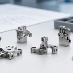
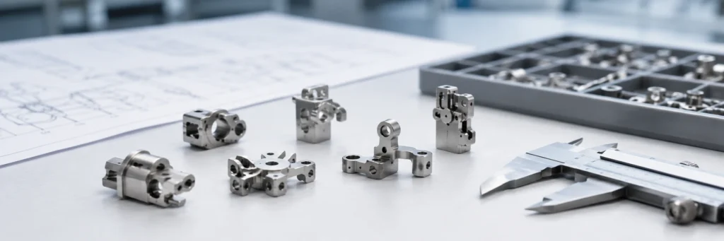
Bu görsel ana eleme mantığını tanıtmaktadır: bir MIM projesi, yalnızca bir şekil oluşturma süreci olarak değil, eksiksiz bir üretim rotası olarak incelenmelidir.
Hızlı Karar: Parçanızın MIM'e Uygun Olup Olmadığını Nasıl Anlarsınız
Tedarikçileri karşılaştırmadan veya fiyat istemeden önce, parçayı üç mühendislik çıktısından birine sınıflandırın. Bu, MIM'i CNC işleme, toz metalurji, döküm veya damgalama için evrensel bir yedek olarak ele almak yerine, tartışmayı üretilebilirliğe odaklanmış tutar. Nihai taramadan önce bileşen kategorisine göre örneklere ihtiyacınız varsa, MIM parçaları uygulama seçimi dişliler, menteşeler, braketler, miller, pimler, tıbbi parçalar, elektronik parçalar ve kompakt yapısal bileşenler gibi yaygın parça ailelerini karşılaştırmak için yolu kullanın.
İyi MIM adayı
Çizim incelemesine hazır
Parça küçük, kompakt, karmaşık, metal, yıllık talebi istikrarlı ve gerçekçi tolerans ve yüzey gereksinimlerine sahip. Yalnızca seçili özellikler ikincil işleme veya yüzey işlemesi gerektirir.
Mühendislik incelemesi gerektirir
Yeniden tasarım sonrası mümkün
Parça MIM'e uygun olabilir, ancak duvar geçişleri, derin delikler, kozmetik alanlar, datum özellikleri, kaplama gereksinimleri veya inceleme standartları kalıplama öncesinde gözden geçirilmelidir.
Kötü MIM uyumu
Önce başka bir yöntem kullanın
Parça yalnızca prototip, çok büyük, uzun ve düz, tamamen datum kritik, toleranssız ayna kozmetik veya geleneksel presleme, damgalama, döküm veya CNC için çok basit.
Mühendislik kuralı: Geometri, malzeme, üretim hacmi, tolerans, büzülme kontrolü, ikincil işlemler ve inceleme yöntemi arasındaki ilişkiye göre MIM'i seçin. Parça belirli bir endüstriye ait olduğu için yalnızca MIM'i seçmeyin.
MIM Uygulama Seçimi Neden Önemlidir
Kötü bir MIM kararı genellikle teklif aşamasında başarısız olmaz. Kalıp, enjeksiyon kalıplama, bağlayıcı giderme, sinterleme, ısıl işlem, parlatma, kaplama, PVD kaplama, montaj veya seri üretim muayenesi sırasında başarısız olur. Bu nedenle MIM uygulama seçimi, yalnızca bir satın alma karşılaştırması değil, bir mühendislik kararı olarak ele alınmalıdır.
MIM, yalnızca tam üretim rotası incelendikten sonra seçilmelidir: metal tozu ve bağlayıcı, besleme stoğu kararlılığı, kalıp akışı, yolluk konumu, bağlayıcı giderme riski, sinterleme büzülmesi, yoğunluk ve gözeneklilik, boyutsal kararlılık, ısıl işlem, sinterleme sonrası işleme, parlatma, kaplama, PVD, kumlama, pasivasyon, inceleme ve parti tutarlılığı. Daha geniş bir proses geçmişi için, şunları gözden geçirin: metal enjeksiyon kalıplamaya genel bakış ve MIM tasarım kılavuzu.
ASTM B883 ferrous MIM malzeme spesifikasyonu için geçerlidir çünkü metal tozlarının bağlayıcılarla karıştırılması, bir kalıba enjekte edilmesi, bağlayıcının giderilmesi ve ardından ısıl işlemle veya ısıl işlem olmaksızın sinterlenmesiyle üretilen demir bazlı metal enjeksiyon kalıplama malzemelerini kapsar. Bu, mühendislere ve alıcılara yalnızca tedarikçi ifadelerine güvenmek yerine bir malzeme spesifikasyonu referansı sunar.
MPIF Standard 35-MIM mühendisler ve alıcıların metal enjeksiyon kalıplanmış parçalar için ortak bir malzeme referansına ihtiyaç duyduğu durumlarda geçerlidir. RFQ, numune alma, çizim incelemesi, malzeme onayı ve üretim kabulü sırasında belirsizliğin azaltılmasına yardımcı olur. Çizime özel toleransların, fonksiyonel testlerin, yoğunluk doğrulamasının veya üretim validasyonunun yerini almaz.
Daha geniş proses anlayışı için, Metal Enjeksiyon Kalıplama Derneği proses özeti besleme stoğu hazırlama, kalıplama, bağlayıcı giderme, kahverengi parça taşıma, sinterleme, büzülme, yoğunluk ve ikincil işlemleri açıklar. Avrupa Toz Metalurjisi Derneği MIM sayfası MIM'i, metal tozlarının bağlayıcılarla karıştırılması, bir kalıba enjekte edilmesi, bağlayıcının giderilmesi ve ardından ısıl işlemle veya ısıl işlem olmaksızın sinterlenmesiyle üretilen demir bazlı metal enjeksiyon kalıplama malzemelerini kapsar. Bu, mühendislere ve alıcılara yalnızca tedarikçi ifadelerine güvenmek yerine bir malzeme spesifikasyonu referansı sunar.
Hızlı MIM Uygulama Seçim Skor Kartı
Bu kontrol listesini bir RFQ göndermeden önce kullanın. Birkaç öğe inceleme veya kötü uyum sütununa düşerse, parça hala mümkün olabilir, ancak yeniden tasarıma, ikincil işlemlere, daha sıkı doğrulamaya veya başka bir üretim sürecine ihtiyaç duyar.

Bu puan kartı, mühendislerin ve satın alma uzmanlarının parçanın çizim incelemesine, yeniden tasarıma veya farklı bir işlem rotasına yönlendirilip yönlendirilmeyeceğini belirlemesine yardımcı olur.
| Seçim Faktörü | İyi MIM Sinyali | İnceleme Gerekli | Muhtemelen Uygun Değil |
|---|---|---|---|
| Parça boyutu | Kontrollü kütleye sahip küçük, kompakt metal parça | Dengesiz kütleye veya uzun desteksiz alanlara sahip orta boy | Bağlayıcı giderme ve sinterleme distorsiyonunun hakim olduğu büyük, ağır veya kalın parça |
| Geometri | Çok yüzeyli özellikler, yuvalar, nervürler, boss'lar, undercut'lar, ince detaylar | Derin kör delikler, ince kollar, keskin iç köşeler, kalın yerel boss'lar | Geleneksel PM veya talaşlı imalata daha uygun basit eksenel preslenmiş şekil |
| Hacim | Orta ila yüksek yıllık istikrarlı talep | Güvenilir bir üretim artış planı ile pilot hacim | Sadece prototip projesi veya sık tasarım değişiklikleri |
| Et kalınlığı | Düzgün geçişler ve makul radyuslara sahip dengeli kesitler | Yerel kalın bölgeler, izole edilmiş yükseltiler, asimetrik kütle dağılımı | Yeniden tasarlanamayan ani kalın-ince geçişler |
| Tolerans | Genel kalıplanmış boyutlar artı seçilmiş işlenmiş özellikler | Birkaç kritik fonksiyona sahip boyutun gözden geçirilmesi gerekiyor | Her boyut dar, datum-kritik veya muayene-kritik |
| Malzeme | Kanıtlanmış MIM paslanmaz çelik, düşük alaşımlı çelik, yumuşak manyetik alaşım, titanyum alaşımı veya tungsten alaşımı yolu | Özel malzeme, ısıl işlem, manyetik, korozyon veya aşınma gereksinimi doğrulanmalı | Malzeme mevcut değil veya MIM yolu için doğrulanmamış |
| Yüzey kalitesi | Sinterlenmiş, kumlama yapılmış, pasivize edilmiş, parlatılmış, kaplanmış veya PVD, net kriterlerle | Görünür yüzeyler, kozmetik bölgeler, kaplama yolu, gözenek kabulü tanımlanmalı | Ayna-kozmetik yüzey, parlatma payı veya gözenek kabulü olmadan |
| Fonksiyon | Aşınma, korozyon, montaj, tork, kilitleme, kayma, manyetik veya kompakt mekanizma fonksiyonları test edilebilir. | Fonksiyon, yoğunluğa, sertliğe, yorgunluğa, kaplamaya veya yüzey durumuna bağlıdır. | Proje özelinde bir doğrulama planı olmayan güvenlik açısından kritik yorulma veya yük durumu |
| Maliyet | Kalıp maliyeti, sabit üretim hacmi üzerinden amorti edilebilir. | İşleme ve son işlem verimi kontrol altında tutulursa kalıp kabul edilebilir. | Düşük yıllık talep veya aşırı ikincil işlemler, MIM'in maliyet avantajını ortadan kaldırır. |
Parça Tipine Göre MIM Uygulama Seçim Matrisi
Uygulama seçimi, yalnızca endüstri adına göre değil, parça tipine ve fonksiyonel riske göre değerlendirilmelidir. Bir medikal çene, kilit kamı, giyilebilir menteşe ve otomotiv braketi, hepsi küçük MIM parçaları olabilir, ancak malzeme, geometri, son işlem veya denetim yanlış seçilirse her biri farklı nedenlerle başarısız olur.
| Parça Türü | MIM Neden Uygun Olabilir | Ana Risk | Kalıplama Öncesi Doğrulanacaklar |
|---|---|---|---|
| Küçük dişli veya tahrik bileşeni | Kompakt metal geometri, küçük dişler, tekrarlanabilir üretim, azaltılmış işleme | Diş doğruluğu, aşınma, ısıl işlem deformasyonu, yoğunluk varyasyonu | Malzeme kalitesi, sertlik, diş toleransı, sinterleme sonrası ölçülendirme veya işleme, fonksiyonel test yöntemi |
| Kilit kamı, mandal veya küçük mekanizma | Karmaşık şekil, kayar temas, tork fonksiyonu, yüksek tekrarlanabilirlik potansiyeli | Aşınma, sertlik, kaplama yapışması, kayar yüzey pürüzlülüğü | Temas alanı, tork gereksinimi, yağlama, sertlik, korozyon koruması, çevrim testi |
| Giyilebilir menteşe veya elektronik donanım | Kompakt geometri ve montaj özelliklerine sahip küçük kozmetik metal parça | Görünür gözenekler, parlatma izleri, yolluk izleri, PVD kusurları | Kozmetik alan, parlatma rotası, gözenek kabulü, kaplama kalınlığı, görsel muayene standardı |
| Tıbbi alet çenesi veya kelepçesi | Karmaşık fonksiyonel geometriye sahip küçük paslanmaz çelik bileşen | Fonksiyonel kenar doğruluğu, pasivasyon, yüzey temizliği, datum kontrolü | Kritik datum, işlenmiş yüzey, malzeme spesifikasyonu, pasivasyon, fonksiyonel temas testi |
| Otomotiv küçük braketi veya destek parçası | Tekrarlanan hacimli ve montaj fonksiyonlu kompakt metal parça | Düzlük, et kalınlığı geçişi, sinterleme desteği, ısıl işlem deformasyonu | Et kalınlığı dengesi, setter desteği, yolluk konumu, kalıplama operasyonu, parti muayene planı |
| Sensör veya yumuşak manyetik bileşen | Kontrollü şekle sahip küçük manyetik veya korozyona dayanıklı parça | Manyetik performans, yoğunluk, ısıl işlem rotası, test yöntemi | Manyetik gereksinim, malzeme rotası, yoğunluk, ısıl işlem, muayene ve doğrulama kriterleri |
Parçanızın MIM'e Uygun Olup Olmadığını Onaylamanız mı Gerekiyor?
Çizimi, 3D CAD dosyasını, malzeme gereksinimini, tahmini yıllık hacmi, kritik boyutları, yüzey işlemesini, kaplama veya ısıl işlem gereksinimlerini ve uygulama geçmişini gönderin. XTMIM, kalıplama veya numune öncesinde parçanın iyi bir MIM adayı olup olmadığını, yeniden tasarım sonrası mümkün olup olmadığını veya başka bir üretim rotasına daha uygun olup olmadığını inceleyebilir.
MIM Ne Zaman Kullanılmalı
MIM genellikle parça küçük, metalden yapılmış, işlenmesi pahalı ve tekrarlanabilir üretim hacminde gerektiğinde düşünülmeye değerdir. Parçada çoklu delikler, çıkıntılar, yuvalar, iç şekiller, alttan kesikler, küçük mekanik özellikler veya işlenmesi zor malzeme gereksinimleri olduğunda daha cazip hale gelir.
İyi bir MIM adayı genellikle birkaç koşulu karşılar. Yıllık hacim kalıp takımını haklı çıkarabilir. Malzeme kanıtlanmış bir MIM malzemesi olarak mevcuttur. Çizim gerçekçi kalıplanmış toleranslara izin verir. Sadece seçilen kritik özellikler sinterleme sonrası işleme gerektirir. Yüzey kalitesi gereksinimleri kalıplamadan önce tanımlanır. Montaj işlevi mastarlar veya fonksiyonel testlerle doğrulanabilir. Tedarikçi bağlayıcı giderme, sinterleme büzülmesi, yoğunluk ve parti tutarlılığını kontrol edebilir.
MIM, gereksiz işlemeyi azalttığı ancak işlevin gerçekten ihtiyaç duyduğu yerde işlemeye izin verdiği için en güçlüdür. Olgun bir MIM projesi her özelliği nihai hassasiyete kalıplamaya çalışmaz. Net-şekle yakın geometriyi fonksiyonel yüzeylerden, referans yüzeylerden, kozmetik alanlardan ve muayene kritik boyutlardan ayırır.
En uygun geometri
Çok yönlü özelliklere, nervürlere, deliklere, pablara, yuvalara, mikro detaylara veya aşırı CNC takım yolları gerektirecek geometrilere sahip küçük kompakt parçalar.
En uygun proje aşaması
Tasarım kararlıdır, üretim talebi güvenilirdir ve alıcı teknik resimleri, CTQ boyutlarını, malzeme gereksinimlerini ve fonksiyonel test ihtiyaçlarını sağlayabilir.
En uygun maliyet mantığı
Kalıp maliyeti üretim hacmine yayılabilir ve MIM rotası işleme süresini, malzeme israfını veya montaj karmaşıklığını azaltır.
MIM Ne Zaman Kullanılmamalı
İşlem riskinin faydasından daha yüksek olduğu durumlarda MIM en iyi seçenek değildir. Bu durum genellikle bir parçanın çok büyük, çok düz, çok kozmetik, tolerans açısından çok kritik veya yıllık hacminin çok düşük olduğu durumlarda görülür. Bir şekil geleneksel presleme ve sinterleme ile yapılabildiğinde, MIM gereksiz yere pahalı olabilir. Süreç seçimi, MIM'in her zaman daha iyi olduğunu varsaymak yerine geometri, miktar, işlev ve doğrulama gereksinimlerinden başlamalıdır.
| MIM Ne Zaman Kullanılmamalı | Neden Sorunlara Yol Açar | Daha İyi Seçenek |
|---|---|---|
| Çok düşük hacimli proje | Takım maliyeti yeterli sayıda parçaya yayılamaz | CNC işleme, prototip işleme veya metal 3B baskı |
| Büyük metal parça | Bağlayıcı giderme süresi, fırın desteği ve sinterleme distorsiyonu zorlaşır | Döküm, dövme, CNC işleme, PM veya imalat |
| Uzun düz parça | Bağlayıcı giderme ve sinterleme sırasında yüksek eğrilme riski | Presleme, CNC işleme, yeniden tasarım veya boyutlandırma işlemi |
| Keskin iç köşeler | Gerilim yoğunluğu, besleme stoğu dolum riski ve çatlama riski artar | Kalıplama öncesinde radyüs ekleyin veya geometrüyü yeniden tasarlayın |
| Derin kör delikler | Besleme stoğu dolumu, bağlayıcı giderme ve toz paketleme dengesiz olabilir | Sinterleme sonrası deliği işleyin veya özelliği yeniden tasarlayın |
| Çok kalın yerel bos | Diferansiyel büzülme ve iç gözeneklilik riski artar | Boşaltın, kütleyi azaltın, et kalınlığını dengeleyin |
| Aynalı yüzey, pay bırakılmadan | Parlatma, gözenekleri, ayırma hatlarını veya besleme izlerini ortaya çıkarabilir | İşlenmiş malzemeden CNC veya kontrollü bir MIM bitirme rotası |
| Tüm boyutlar sıkı toleranslıdır | Sinterleme büzülmesindeki değişkenlik doğrudan kontrolü zorlaştırır | MIM artı işleme, boyutlandırma, taşlama veya CNC işleme |
MIM vs CNC vs PM: Proses Seçim Tablosu

Bu karşılaştırma, RFQ öncesinde prototip rotalarını, standart pres şekil rotalarını ve MIM'e uygun küçük karmaşık metal parçaları ayırmaya yardımcı olur.
| Süreç | En İyi Kullanım Durumu | Ana Avantaj | Ana Sınırlama | Seçim Tavsiyesi |
|---|---|---|---|---|
| Metal enjeksiyon kalıplama | Orta-yüksek hacimde küçük karmaşık metal parçalar | Karmaşık 3D geometri, azaltılmış işleme | Kalıp maliyeti, sinterleme büzülmesi, bağlayıcı giderme riski, sinterleme distorsiyonu | Hacim ve geometri kalıplamayı haklı çıkardığında kullanın |
| CNC işleme | Prototipler, düşük hacim, referans kritik özellikler | Sıkı boyutsal kontrol ve tasarım esnekliği | Tekrarlayan karmaşık küçük parçalar için pahalı | Prototipler veya hassas işlem sonrası özellikler için kullanın |
| Geleneksel PM | Hacimli basit preslenmiş şekiller | Eksenel preslenmiş parçalar için verimli | Sınırlı yan özellikler ve karmaşık 3D geometri | Daha basit şekiller ve daha az geometri serbestisi için kullanılır |
| Basınçlı döküm | Yüksek hacimde demir dışı parçalar | Çinko veya alüminyum alaşımları için hızlı üretim ve iyi şekil kabiliyeti | Alaşım sınırlaması, gözeneklilik riski ve farklı mukavemet profili | Uygun demir dışı parçalar için kullanılır, doğrudan paslanmaz MIM yedek parçası olarak değil |
| Sac metal şekillendirme | İnce sac metal parçalar | Şekillendirilmiş sac parçalar için düşük maliyetli seri üretim | Sınırlı kalınlık ve kompakt 3D geometri | İnce şekillendirilmiş parçalar için kullanılır, kompakt 3D mekanizmalar için değil |
MIM ve CNC sadece bir fiyat karşılaştırması değildir. CNC genellikle prototipler, düşük hacimler, sıkı datums ve sık tasarım değişiklikleri için daha iyidir. MIM, geometri karmaşık olduğunda, hacim kararlı olduğunda ve ikincil işleme sınırlı sayıda kritik özelliğe indirgendiğinde daha rekabetçi hale gelir. Mevcut çizim, tekrarlanan üretim için değerlendirilen işlenmiş bir parça ise, MIM'i doğrudan bir ikame olarak kabul etmeden önce CNC'den MIM'e dönüştürme kılavuzunu inceleyin. İşleme rotası farklılıkları hakkında arka plan bilgisi için CNC işleme ile ilgili süreç sayfası.
MIM ve PM de basit bir değiştirme kararı değildir. Geleneksel PM, daha basit preslenmiş şekiller için verimlidir, oysa MIM, daha karmaşık üç boyutlu özelliklere, yan özelliklere ve minyatür mekanizmalara sahip daha küçük parçalar için daha iyidir. MIM ve PM, inceleme yapılmadan aynı çizim varsayımlarını paylaşmamalıdır. Daha geniş bir rota karşılaştırması için şurayı inceleyin: ilgili bir süreç olarak toz metalurjisi.
Malzeme Seçiminin MIM Uygulama Uygunluğunu Nasıl Etkilediği
Malzeme seçimi, endüstri alışkanlığından değil, gerçek arıza modundan başlamalıdır. Giyilebilir bir menteşe, kilit kamı, tıbbi çene, otomotiv braketi ve küçük bir dişli hepsi MIM parçası olabilir, ancak aynı malzemeye ihtiyaç duymazlar. Korozyon direnci, sertlik, aşınma, yoğunluk, manyetik davranış, ısıl işlem yanıtı, parlatma, kaplama, PVD ve maliyet birlikte gözden geçirilmelidir. Detaylı malzeme sayfaları için şurayı kullanın: MIM malzemeleri seçim merkezi.
| MIM Malzemesi | Tipik Kullanım | Neden Seçilir | Ana Seçim Riski Kontrol Edilmeli |
|---|---|---|---|
| 316L paslanmaz çelik | Tıbbi aletler, elektronikler, saatler, korozyonla ilgili donanımlar | Korozyon direnci ve işlenebilirlik | Tasarım veya yüzey işleme desteği olmadan yüksek aşınma veya yüksek sertlik için ideal değildir |
| 17-4PH paslanmaz çelik | Yapısal küçük parçalar, kilitler, otomotiv, endüstriyel donanım | Çökelme sertleşmesi sonrası dayanım | Isıl işlem distorsiyonu ve boyutsal değişim |
| 420 paslanmaz çelik | Aşınma parçaları, kilit bileşenleri, takımlar, küçük miller | Sertleşebilirlik ve aşınma direnci | 316L'ye göre daha düşük korozyon direnci; ısıl işlem kontrolü önemlidir |
| 430 paslanmaz çelik | Manyetik parçalar, sensörle ilgili donanımlar | Manyetik davranış ve paslanmaz korozyon direnci | Manyetik ve mekanik performans testlerle doğrulanmalıdır |
| Düşük alaşımlı çelik | Otomotiv, takımlar, kilitler, endüstriyel parçalar | Mukavemet, tokluk, aşınma direnci, ısıl işlem tepkisi | Genellikle korozyon koruması gereklidir |
| Titanyum alaşımı | Seçilmiş tıbbi, giyilebilir veya hafif donanım uygulamaları | Düzgün doğrulandığında düşük yoğunluk, korozyon direnci ve seçilmiş biyouyumluluk gereksinimleri | Daha yüksek malzeme maliyeti ve daha sıkı proses kontrolü; nihai kullanım malzeme rotasına ve doğrulamaya bağlıdır |
| Tungsten alaşımı | Karşı ağırlıklar, titreşim kontrolü, kompakt kütleli parçalar | Küçük hacimde yüksek yoğunluk | Ağır geometri, bağlayıcı giderme, sinterleme ve deformasyon riskini artırır; tedarikçi yeteneği doğrulanmalıdır |
Mühendislik eğitimi için bileşik alan senaryosu: bir kilit kamı boyut denetiminden geçti ancak çevrim testleri sırasında erken aşınma gösterdi. Seçilen paslanmaz malzeme kabul edilebilir korozyon direncine sahipti ancak tekrarlanan kayma teması için yetersiz sertliğe sahipti. Düzeltme, sertleştirilebilir bir grade'e geçmek, ısıl işlem eklemek ve işlem sonrası sertliği doğrulamaktı. Kilit ve mekanik donanım projeleri, MIM malzemesini onaylamadan önce tork, temas alanı, yağlama, sertlik, aşınma testleri, ısıl işlem yanıtı ve korozyon korumasını gözden geçirmelidir.
MIM Toleransları ve Sinterleme Sonrası İşleme Nasıl Değerlendirilir
MIM toleransları özellik türüne göre tartışılmalıdır. Bir tedarikçi genel boyutları kalıp telafisi ve proses kontrolü ile tutabilir, ancak datum-kritik boyutlar, yatak bağlantıları, sızdırmazlık yüzeyleri, dişliler, kayan yüzeyler ve hassas delikler genellikle işleme, boyutlandırma, raybalama, taşlama veya parlatma gerektirir. Bu nedenle MIM uygunluğu, şunlarla birlikte gözden geçirilmelidir: MIM tasarım kılavuzu, sadece bir malzeme veya uygulama listesi okuyarak değil.
| Özellik Türü | Doğrudan Kalıplanabilir mi? | İkincil İşlem Ne Zaman Eklenmeli |
|---|---|---|
| Dış profil | Genellikle evet | Profil montaj boşluğunu veya kozmetik kenarı kontrol ettiğinde |
| Kritik olmayan delikler | Genellikle evet | Delik konumu, yuvarlaklığı veya dikliği kritik olduğunda |
| Dişli delikler | Bazen mümkün, ancak genellikle riskli | Güvenilir montaj için sinterleme sonrası işleme veya kılavuz çekme |
| Yatak geçmesi | Genellikle son işlem gerektirir | Talaşlı imalat, raybalama, boyutlandırma veya taşlama |
| Sızdırmazlık yüzeyi | Genellikle son işlem gerektirir | Talaşlı imalat, lepleme, parlatma veya taşlama |
| Kayma yüzeyi | Aşınma ve pürüzlülük gereksinimine bağlıdır | Parlatma, talaşlı imalat, ısıl işlem, kaplama veya birden fazla işlemin birleştirilmesi |
| Kozmetik görünür yüzey | Kalıplanmış yüzey yeterli olmayabilir | Parlatma, kumlama, PVD, kaplama veya kozmetik standart tanımlama |
| Referans yüzeyi | Dikkatlice incelenmelidir | Referans montaj tolerans zincirini kontrol ediyorsa talaşlı imalat |
Pratik bir MIM çizimi, kalıplanmış boyutları, işlenmiş boyutları, boyutlandırılmış boyutları, kozmetik yüzeyleri, fonksiyonel kalıp boyutlarını ve referans boyutlarını ayırmalıdır. Yeşil parça sinterleme sırasında büzüldüğü için, kritik datums ve hassas bağlantılar sıradan kalıplanmış özellikler gibi ele alınmamalıdır.
Mühendislik eğitimi için bileşik alan senaryosu: bir tıbbi cihaz çenesi, tamamen kalıplanmış bir MIM parçası olarak tasarlandı, ancak kavrama yüzeyi gerekli fonksiyonel teması karşılamadı. Düzeltme, bileşenin sinterleme sonrası işleme ile kavrama yüzeyi ve fonksiyonel referans noktası içeren bir MIM net şekle yakın (near-net-shape) parça olarak yeniden tasarlanmasıydı. Tıbbi MIM parçaları, kalıplama öncesinde kalıplanmış alanları, işlenmiş alanları, parlatılmış yüzeyleri, pasivize edilmiş yüzeyleri ve denetim kontrollü özelliklerini tanımlamalıdır.
Uygulama Seçimi için MIM Tasarım Kılavuzları
Et Kalınlığını Dengeli Tutun
Ani et kalınlığı değişiklikleri, distorsiyon, çatlama ve yerel yoğunluk değişimi riskini artırır. Kalın kesitler, sinterleme sırasında ince kesitlerden farklı şekilde büzülür ve soğur. İyi bir MIM tasarımı, büyük izole bosajlardan, derin kalın bloklardan ve ani geçişlerden kaçınır. Bir bosaj gerekiyorsa, kor delme, yarıçap ekleme veya geçiş geometrisini değiştirmeyi düşünün.
Keskin İç Köşelerden Kaçının
Keskin iç köşeler, gerilim konsantrasyonunu ve dolum riskini artırır. Ayrıca bağlayıcı giderme veya sinterleme sırasında çatlak başlangıç noktaları haline gelebilirler. Fonksiyonun izin verdiği her yerde, özellikle bosajlar, yuvalar, kaburgalar, delikler ve kalın ile ince kesitler arasındaki geçişlerde yarıçaplar ekleyin.
Yolluk Konumunu Erken Gözden Geçirin
Yolluk konumu; akış, kaynak hatları, ayırma hattı yerleşimi, yoğunluk homojenliği ve kozmetik yüzey riskini etkiler. Görünür parçalar için, yolluk ve ayırma hattı pozisyonları kalıplamadan önce, ilk numunelerden sonra değil, gözden geçirilmelidir. Kozmetik olmayan bir yüzeydeki yolluk izlerini yönetmek, görünür cilalı bir yüzeydeki yolluk izlerinden genellikle daha kolaydır.
Sinterleme Desteğini Tasarımın Bir Parçası Olarak Ele Alın
CAD'de kararlı görünen bir parça, uzun desteksiz açıklıklara, dengesiz kütleye veya asimetrik geometriye sahipse sinterleme sırasında deforme olabilir. Sinterleme desteği, setter tasarımı ve parça oryantasyonu, DFM tartışmasının bir parçası olmalıdır. Düzlük, doğrultu veya montaj hizalaması gereksinimleri olan parçalar için tedarikçi, parçanın fırında nasıl destekleneceğini açıklamalıdır.
MIM'i Kesmesiz CNC Olarak Tasarlamayın
Bir CNC tasarımı genellikle işlenmesi kolay ancak kalıplanması ve sinterlenmesi riskli özellikler içerir. CNC'den MIM'e geçiş yaparken, çizimi doğrudan kopyalamak yerine et kalınlığı dengesi, referans noktaları, delikler, nervürler, bosslar, derin oluklar, keskin kenarlar ve bitirme yöntemlerini gözden geçirin.
Yüzey Kalitesi Seçimi: Parlatma, Kaplama, PVD, Kumlama, Pasivasyon

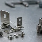
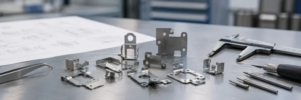
Bu görsel, bitirme kararını desteklemektedir: kozmetik, kayar, kaplamalı ve korozyonla ilgili yüzeyler, yalnızca numune reddinden sonra değil, kalıplama öncesinde incelenmelidir.
MIM yüzey kalitesi, yalnızca görünüme değil, işleve göre seçilmelidir. Sinterleme sonrası kabul edilebilir görünen bir yüzey, parlatma, kaplama veya PVD sonrası farklı davranabilir. Gözenekler, ayırma hatları, yolluk izleri, akış izleri ve parlatma dalgaları, son işlemden sonra daha belirgin hale gelebilir. Daha derin proses planlaması için inceleyin MIM ikincil işlemler.
| Yüzey Kalitesi | Uygun Olduğu Durumlar | Kontrol Edilmesi Gereken Riskler |
|---|---|---|
| Sinterlenmiş | İç parçalar, kozmetik olmayan mekanizmalar | Pürüzlülük, ayırma hattı, yolluk izi |
| Tamburlama veya çapak alma | Genel kenar iyileştirme | Kenar yuvarlatma ve küçük özellik hasarı |
| Kum püskürtme | Mat görünüm, yüzey homojenliği | Küçük özelliklerde boyutsal etki |
| Parlatma | Kozmetik yüzeyler, kayma yüzeyleri | Gözenekler açılabilir ve görünür hale gelebilir |
| Pasivasyon | Paslanmaz tıbbi veya korozyonla ilgili parçalar | Yüzey temizliği ve malzeme uyumluluğu |
| Elektrokaplama | Dekoratif veya korozyon koruması | Çukurlar, gözenekler, yapışma, kalınlık kontrolü |
| PVD | Aşınma veya dekoratif kaplama | Gözenekler ve parlatma kusurları daha görünür hale gelebilir |
| Isıl işlem | Mukavemet, sertlik, aşınma direnci | Distorsiyon, sertlik değişimi, boyutsal değişim |
Kozmetik MIM parçaları için temel soru, parçanın parlatılıp parlatılamayacağı değil. Daha iyi soru, hangi gözenek seviyesi, yoğunluk, parlatma payı, kaplama rotası ve kozmetik denetim yönteminin kabul edilebilir olduğudur.
Mühendislik eğitimi için bileşik alan senaryosu: bir giyilebilir cihaz menteşesi, sinterleme ve parlatma sonrası boyutsal denetimi geçti, ancak PVD kaplama sonrası küçük çukurlar ve koyu lekeler belirdi. Parlatma işlemi yüzeye yakın gözenekleri açtı ve PVD kaplama, yansıyan ışık altında onları daha görünür hale getirdi. Görünür MIM parçaları, kalıplama öncesinde kozmetik yüzeyleri, kaplama rotasını, kabul edilebilir çukurları, parlatma payını, denetim aydınlatmasını ve nihai görünüm standardını tanımlamalıdır.
Yaygın MIM Kusurları ve Uygulama Seçimini Nasıl Etkilerler
Yaygın MIM kusurları genellikle besleme stoğu kararlılığı, kalıplama koşulları, bağlayıcı giderme yolu, sinterleme desteği, et kalınlığı dengesi, fırın yüklemesi, ısıl işlem ve bitirme yolu ile bağlantılıdır. Bir kusur sadece görsel bir sorun olarak ele alınmamalıdır. Genellikle montaj, yüzey kalitesi, mukavemet veya parti tutarlılığını etkileyebilecek bir tasarım veya proses zayıflığına işaret eder.
| MIM Kusuru | Genellikle Anlamı | Uygulama Riski | Düzeltici Yön |
|---|---|---|---|
| Çarpılma | Dengesiz büzülme veya zayıf sinterleme desteği | Montaj hatası, zayıf düzlük | Et kalınlığını dengeleyin, fırın destek aparatını iyileştirin, boyutlandırma ekleyin |
| Çatlama | Bağlayıcı giderme gerilimi, keskin köşeler, kalın kesitler | Mukavemet hatası veya reddedilme | Köşe radyusları ekleyin, bağlayıcı gidermeyi yavaşlatın, kalın alanları yeniden tasarlayın |
| Kabarcık oluşumu | Sıkışmış gaz veya eksik bağlayıcı giderme | Kozmetik ve yapısal kusurlar | Bağlayıcı giderme yolunu ve besleme stoğu kontrolünü iyileştirin |
| Eksik dolum | Zayıf akış, ince nervürler, kötü besleme tasarımı | Eksik özellikler, zayıf küçük detaylar | Beslemeyi değiştirin, kalıplamayı ayarlayın, radyus ekleyin |
| Porozite | Toz, sinterleme veya kirlenme sorunu | Düşük mukavemet, zayıf parlatma, kaplama çukurları | Tozu, fırın profilini, yoğunluk testini gözden geçirin |
| Boyutsal kayma | Sinterleme büzülmesi değişkenliği, kalıp aşınması, fırın yüklemesi | Montaj ve muayene hatası | SPC, boşluk takibi, fonksiyonel mastarlar kullanın |
| Parlatma sonrası yüzey çukurları | Yüzeye yakın açık gözenekler | Kaplama veya PVD sonrası kozmetik reddi | Yoğunluğu iyileştirin, parlatma ve kaplama yolunu ayarlayın |
Tedarikçi değerlendirmesi için faydalı bir MIM tartışması, kusurları kök neden, denetim yöntemi ve düzeltici eylem ile ilişkilendirmelidir. İnceleyin MIM kalite kontrol yeteneğini inceleyin parçanın kritik boyut, yoğunluk, sertlik, yüzey veya fonksiyonel test gereksinimleri olduğunda.
MIM Maliyet Sürücüleri ve Kalıp Amortismanı
MIM maliyeti, birim fiyatla değil, toplam üretim yoluyla değerlendirilmelidir. Tasarım aşırı işleme, düşük verimli parlatma, tekrarlanan kaplama revizyonu veya kararsız muayene sonuçları gerektiriyorsa düşük birim fiyatın faydası yoktur.
Başlıca MIM maliyet sürücüleri arasında parça boyutu ve ağırlığı, malzeme sınıfı, toz maliyeti, bağlayıcı ve besleme stoğu karmaşıklığı, boşluk sayısı, kalıp karmaşıklığı, kalıplama çevrim süresi, bağlayıcı giderme süresi, sinterleme fırın yükü, fire oranı, ısıl işlem, işleme veya boyutlandırma, parlatma, kaplama, PVD, pasivasyon, kumlama, muayene gereksinimleri, paketleme ve taşıma yer alır.
Kalıp maliyeti önemlidir çünkü MIM bir kalıp gerektirir. Düşük hacimli bir proje teknik olarak cazip görünebilir ancak ekonomik olarak başarısız olabilir. Yüksek hacimli bir proje kalıp aşamasında pahalı görünebilir ancak işleme süresi azaldığında ve maliyet üretim hacmine yayıldığında makul hale gelir. Bu nedenle MIM maliyeti, kalıp amortismanı, beklenen yıllık hacim, hurda riski ve ikincil operasyon verimi ile birlikte değerlendirilmelidir.
MIM Parçaları için Prototip ve Numune Kontrol Listesi
| Numune Kalemi | Kontrol Edilecekler | Neden Önemlidir |
|---|---|---|
| Malzeme sertifikası | Kalite, kimyasal bileşim, tedarikçi rotası | Malzeme temelini doğrular |
| Ham parça incelemesi | Dolum, kaynak hatları, yolluk, çapak | Kalıplama risklerini erken bulur |
| Bağlayıcı giderme sonucu | Çatlaklar, kabarcıklar, distorsiyon | Bağlayıcı giderme kararlılığını onaylar |
| Sinterlenmiş boyutlar | Büzülme ve ana özellikler | Kalıp telafisini doğrular |
| Yoğunluk | Yoğunluk hedefi ve gözeneklilik | Mukavemet, yorulma, parlatma, kaplamayı etkiler |
| Sertlik | Sinterlenmiş veya ısıl işlem görmüş sertlik | Malzeme ve ısıl işlemi onaylar |
| Mikroyapı | Gözenekler, kirlenme, tane durumu | Kritik parçalar için faydalı |
| Yüzey kalitesi | Pürüzlülük, çukurlar, ayırma hattı, besleme izi | Kozmetik ve kaplama sürprizlerini önler |
| Montaj testi | Uyum, tork, kayma, kilitlenme | Gerçek işlevi doğrular |
| Proses tekrarlanabilirliği | Birden çok parti veya boşluk | Seri üretim riskini azaltır |
Satın Alma ve RFQ Kontrol Listesi
Bir MIM fiyat teklifi istemeden önce alıcılar; 3B model, 2B çizim, malzeme gereksinimi, yıllık hacim tahmini, hedef uygulama, kritik boyutlar, yüzey kalitesi gereksinimi, ısıl işlem gereksinimi, kaplama veya kaplama gereksinimi, kozmetik yüzey tanımı, mekanik test gereksinimi, muayene yöntemi, paketleme gereksinimi, prototip takvimi ve seri üretim takvimi sağlamalıdır.
Tedarikçiden MIM uygulanabilirliğini, önerilen malzemeyi, kalıp varsayımlarını, beklenen sinterleme büzülmesi riskini, işleme gerektiren kritik boyutları, yüzey işleme yolunu, tahmini kalıp maliyetini, hacme göre tahmini birim maliyeti, numune planını, muayene planını ve olası başarısızlık risklerini teyit etmesini isteyin.
Güçlü bir RFQ sadece “bu parçanın fiyatı ne kadar?” diye sormaz. Parçanın gerçekten MIM için uygun olup olmadığını, hangi özelliklerin kalıplanması gerektiğini, hangilerinin işlenmesi gerektiğini, sinterleme ve son işlemlerden sonra hangi risklerin ortaya çıkabileceğini ve üretimi onaylamak için hangi kanıtların kullanılacağını sorgular.
Teklif hazırlığı için:
MIM RFQ hazırlık kılavuzunu okuyun
MIM RFQ hazırlık kılavuzunu okuyun
Doğrudan proje incelemesi için:
MIM fizibilite incelemesi için çiziminizi gönderin
MIM fizibilite incelemesi için çiziminizi gönderin
Nihai Mühendislik Seçim Kuralı
Parça küçük, karmaşık, tekrarlanabilir, malzeme uyumlu ve kalıbı haklı çıkaracak yeterli hacimde üretildiğinde MIM kullanın. Parça büyük, düz, düşük hacimli, işleme payı olmadan yüksek kozmetik kalite gerektiren veya zaten işleme gerektiren sıkı toleranslı kritik boyutlarla dolu olduğunda MIM'den kaçının.
İyi bir MIM uygulama seçimi kararı yalnızca sektör adına veya parça karmaşıklığına dayanmaz. Geometri, malzeme, hacim, tolerans, yüzey kalitesi, kalıp maliyeti, sinterleme büzülmesi, yoğunluk, ikincil işlemler ve muayene stratejisi arasındaki ilişkiye dayanır. Bu faktörler kalıp öncesi gözden geçirildiğinde MIM pratik bir üretim yolu olabilir. Göz ardı edildiklerinde proje ilk teklifi geçebilir ancak numune, son işlem, montaj veya seri üretim sırasında başarısız olabilir.
Mühendislik inceleme notu: bu kılavuz, erken MIM uygulama taraması için tasarlanmıştır. Nihai uygunluk, çizim incelemesine, malzeme bulunurluğuna, kritik boyutlara, yüzey gereksinimlerine, fonksiyonel testlere, yıllık hacme, kalıp varsayımlarına ve tedarikçi proses kabiliyetine bağlıdır.
Standartlar ve teknik referanslar: ASTM B883, MPIF Standard 35-MIM, MIMA işlem ve tasarım kaynakları ve EPMA MIM kaynakları, malzeme spesifikasyonu ve işlem anlayışını destekleyebilir. Bu referanslar, çizime özel DFM incelemesi, tedarikçi yetenek incelemesi, numune onayı veya proje düzeyinde doğrulamanın yerini tutmaz.
Çizime Dayalı MIM Uygunluk İncelemesi Talep Edin
Parçanız küçük, karmaşık, metal ve tekrarlı üretim için planlanmışsa, 2D çizimi, 3D CAD dosyasını, malzeme gereksinimini, tolerans gereksinimini, yüzey işlem ihtiyacını, tahmini yıllık hacmi ve uygulama geçmişini gönderin. XTMIM, kalıplama veya numune öncesinde geometri risklerini, malzeme uygunluğunu, tolerans stratejisini, yüzey işlem rotasını, ikincil işlemleri, muayene gereksinimlerini ve RFQ bilgi boşluklarını inceleyebilir.
SSS: MIM Uygulama Seçim Kılavuzu
MIM seçimi için ilk kural nedir?
İlk kural, parçanın küçük, karmaşık, üretim hacmine uygun ve malzeme uyumlu olup olmadığını teyit etmektir. MIM, yalnızca parça karmaşık bir şekle sahip olduğu için seçilmemelidir.
MIM'i ne zaman CNC işlemeye tercih etmeliyim?
Parça küçük, karmaşık, orta-yüksek hacimli üretilecek ve her kritik özellikte işleme gerektirmiyorsa MIM'i CNC yerine kullanın. CNC genellikle prototipler, düşük hacim, sıkı referans noktaları ve sık tasarım değişiklikleri için daha uygundur.
Prototip amaçlı bir metal parça için MIM kullanabilir miyim?
Genellikle hayır. MIM kalıp gerektirir, bu nedenle prototip odaklı projeler genellikle önce CNC işleme veya metal 3D baskı ile daha iyi test edilir. Tasarım kararlı hale geldiğinde ve güvenilir bir üretim hacmi olduğunda MIM daha uygun hale gelir.
MIM'i ne zaman kullanmamalıyım?
Parça çok büyük, çok düz, çok düşük hacimli, izole bölgelerde çok kalın veya son işlem gerektirmeden ayna yüzey kalitesi ya da ultra sıkı referans toleransları gerektiriyorsa MIM'den kaçının.
Endüstriye veya parça geometrisine göre MIM'i mi seçmeliyim?
Parça geometrisine, malzemeye, toleransa, yüzey işlemine, üretim hacmine ve doğrulama gereksinimlerine göre MIM seçimi yapın. Sektör adı yalnızca arka plan bilgisidir. Tıbbi, otomotiv, elektronik veya kilit uygulamalarındaki bir parça, çizim MIM işlem penceresinin dışındaysa yine de uygun olmayabilir.
MIM parçalar için yaygın olarak hangi malzemeler kullanılır?
Yaygın MIM malzemeleri arasında 316L paslanmaz çelik, 17-4PH paslanmaz çelik, 420 paslanmaz çelik, 430 paslanmaz çelik, düşük alaşımlı çelikler, seçilmiş titanyum alaşımları ve seçilmiş tungsten alaşımları bulunur. Doğru malzeme; korozyon direnci, mukavemet, sertlik, aşınma, yoğunluk, ısıl işlem, yüzey işlem gereksinimleri ve tedarikçi proses kabiliyetine bağlıdır.
MIM parçaları sinterleme sonrası işleme gerektirir mi?
Bazı MIM parçaları sinterlenmiş haliyle kullanılabilir, ancak kritik delikler, yatak geçmeleri, sızdırmazlık yüzeyleri, dişler, kayma yüzeyleri ve hassas referans noktaları genellikle sinterleme sonrası işleme, boyutlandırma, taşlama veya parlatma gerektirir.
MIM kozmetik görünebilir parçalar için uygun mudur?
MIM, bazı kozmetik görünebilir parçalar için kullanılabilir, ancak kalıplama öncesinde yolluk izleri, ayırma hatları, gözenekler, parlatma payı, kaplama rotası ve muayene aydınlatması tanımlanmalıdır. Yoğunluk ve yüzey işlemesi kontrol edilmezse, parlatma, kaplama veya PVD, yüzeye yakın gözenekleri daha görünür hale getirebilir.
MIM uygulamalarındaki en büyük riskler nelerdir?
En büyük riskler arasında sinterleme büzülme varyasyonu, çarpılma, çatlama, gözeneklilik, yetersiz dolum, parlatma veya PVD sonrası yüzey çukurları, ısıl işlem deformasyonu, belirsiz referans noktası stratejisi ve belirsiz muayene standartları yer alır.
Alıcılar bir MIM RFQ'su için ne sağlamalıdır?
Alıcılar 3D model, 2D teknik resim, malzeme gereksinimi, yıllık hacim, kritik boyutlar, yüzey işlem gereksinimi, ısıl işlem veya kaplama ihtiyaçları, muayene yöntemi, fonksiyonel gereksinimler ve uygulama geçmişini sağlamalıdır.