
Cette page présente des pièces MIM personnalisées utilisées dans les assemblages de téléphones mobiles, et non des accessoires de téléphone de remplacement ou des pièces de rechange au détail. XTMIM fabrique des composants de téléphone mobile MIM personnalisés à partir de dessins, y compris des tiroirs de carte SIM, des anneaux d'objectif de caméra, des cadres de caméra, des boutons latéraux, certains composants de charnières de téléphones pliables, du matériel de support d'interface de connecteur et des supports internes compacts. La page est présentée comme une véritable page d'affichage de pièces MIM pour téléphones mobiles, soutenue par un contenu d'analyse technique concis. Elle ne présente pas de grands boîtiers de téléphone ou de simples blindages plats comme principale opportunité MIM.
Les exemples ci-dessous aident les ingénieurs produit, les équipes d'approvisionnement et les chefs de projet à comparer leurs propres composants de smartphone avec de vraies familles de pièces candidates MIM avant d'envoyer des dessins pour une revue de faisabilité. Les candidats les plus solides combinent généralement une petite taille, une géométrie 3D complexe, des parois fines, des trous, des fentes, des nervures, des pattes, des surfaces cosmétiques, des zones de contact ou des exigences de production répétée.
Réponse directe : Les pièces MIM pour téléphones portables les plus adaptées sont de petits composants métalliques nécessitant une géométrie compacte, des dimensions répétables et une qualité de surface contrôlée. Les exemples typiques incluent les tiroirs de carte SIM, les bagues d'objectif de caméra, les cadres de caméra, les boutons latéraux, certains maillons de charnières pliables, le matériel de support de connecteur et les supports internes. L'adéquation finale dépend du dessin, de l'épaisseur de paroi, des notes de tolérance, du matériau, de la finition, de la position d'assemblage et du volume annuel.
Caractéristiques géométriques typiques des pièces MIM pour téléphones portables
Ceci est la section principale d'affichage des pièces pour la page. Elle utilise de vraies images de composants métalliques de téléphones portables pour montrer à la fois les familles de pièces et les caractéristiques géométriques qui rendent ces composants pertinents pour le MIM : tiroirs à parois fines, ouvertures de bagues de caméra, faces de contact des boutons latéraux, maillons de charnières compacts, structures de support de connecteur, supports internes, petits trous, pattes, nervures, bossages et détails de localisation.

Cadres de tiroir minces
Les tiroirs SIM nécessitent généralement des cadres métalliques à parois minces, des bords externes nets, des dimensions d'encoche de carte stables et un contrôle de finition après revêtement ou PVD.

Ouvertures annulaires et références de module
Les bagues et cadres d'objectif d'appareil photo combinent souvent des ouvertures circulaires, des surfaces étagées, de petites zones de localisation et des finitions visibles.

Surfaces externes des boutons
Les boutons latéraux et les boutons d'alimentation sont de petits composants externes où la sensation au toucher, le rayon des bords, l'état de surface et le jeu d'accouplement sont importants.
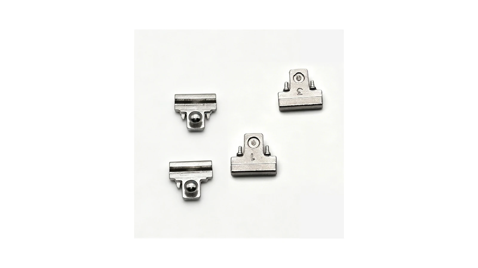
Caractéristiques de pivot, de liaison et de verrouillage
Le MIM peut convenir à certaines liaisons, supports de pivot, pièces de verrouillage ou pièces à contact glissant, tandis que la fonction complète du module de charnière doit encore être examinée au niveau de l'assemblage.
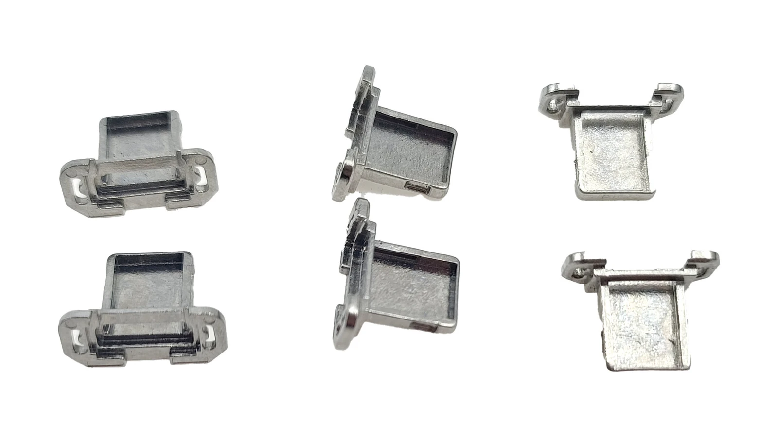
Matériel d'interface compact
Les pièces de support de la zone du port de charge et des E/S peuvent nécessiter un renforcement local, de petits trous, des languettes, des faces de localisation ou une compatibilité de finition.
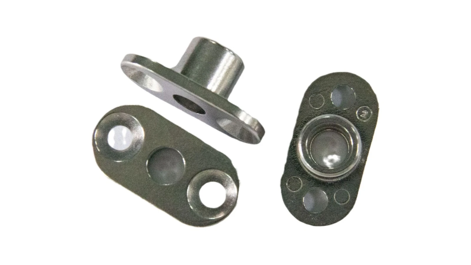
Trous, Bossages, Nervures et Plans de référence
Les supports internes sont de bons candidats pour le MIM lorsque la conception consolide les trous de montage, les nervures, les bossages, les languettes et les plans de référence dans une petite pièce métallique.
Limite d'affichage : Cette page utilise le contexte de l'assemblage de téléphones comme thème principal. Les règles de conception détaillées pour les charnières générales, les supports, les arbres, les goupilles, les engrenages ou les pièces de haute précision doivent rester sur leurs propres pages de familles de structures, tandis que cette page montre comment ces familles de pièces apparaissent à l'intérieur des assemblages de téléphones mobiles.
Matrice d'adéquation MIM pour les composants de smartphone
Cette matrice condensée conserve le jugement technique utile de l'ancienne section de support tout en évitant l'ancien schéma générique. Elle aide les ingénieurs à décider si un composant de téléphone mérite d'être évalué pour le MIM après l'avoir comparé aux exemples de pièces réels ci-dessus.
| Type de pièce de téléphone mobile | Adaptation MIM | Pourquoi elle peut convenir au MIM | Principaux points d'examen | Procédé alternatif à comparer |
|---|---|---|---|---|
| Tiroir de carte SIM | Fort / Dépendant du dessin | Cadre métallique fin, production répétée et surfaces cosmétiques | Planéité, ajustement de fente, déformation, épaisseur de revêtement | Emboutissage, usinage CNC, moulage sous pression |
| Cadre d'appareil photo / bague d'objectif | Fort / Dépendant du dessin | Petit cadre métallique avec caractéristiques cosmétiques et d'assemblage | Référence, surface visible, polissage, revêtement, déformation | Usinage CNC, moulage sous pression, emboutissage |
| Bouton latéral | Conditionnel | Petite pièce métallique cosmétique avec contact répété | Sensation tactile, usure, état de surface, ajustement | Usinage CNC, emboutissage |
| Composant de charnière pliable | Bon candidat | Géométrie complexe, trous, caractéristiques de pivot ou de contact | Alignement, usure, usinage secondaire, déformation | Usinage CNC, emboutissage plus assemblage |
| Matériel de support de connecteur | Conditionnel | Structure de support ou d'interface métallique compacte | Plaquage, ajustement, sections minces, pièces d'accouplement | Emboutissage, usinage CNC |
| Support interne / pièce de positionnement | Conditionnel | Composant structurel ou de positionnement à caractéristiques multiples | Position de trou, stratégie de référence, disposition des nervures | Emboutissage, moulage sous pression, usinage CNC |
| Plaque plate ou blindage simple | Faible | Complexité géométrique insuffisante | Coût, bavures, volume | Emboutissage |
Revue DFM et d'inspection pour les pièces MIM de téléphone
Le contenu DFM doit supporter l'affichage de la pièce, pas le remplacer. Pour les pièces MIM de smartphones, les points de revue les plus importants sont les parois fines, les transitions de section locales, les petits trous, les fentes, les surfaces visibles, l'emplacement de l'alimentation, le retrait de frittage, la marge de finition et les plans de référence d'inspection.
Murs fins et transitions de section
Les parois fines sont courantes dans les plateaux, les cadres et les supports. Des changements brusques d'épaisseur peuvent affecter le flux, le comportement au déliantage, la déformation au frittage et la planéité finale.
Petits trous, fentes et contre-dépouilles
Les trous de pivot, les fentes de plateau, les trous de localisation et les contre-dépouilles compactes nécessitent une revue de moulabilité, de frittage et d'inspection avant l'outillage.
Surfaces esthétiques et emplacement du point d'injection
Les surfaces visibles des téléphones rendent le placement du point d'injection important car les marques de point d'injection ou les perturbations de flux peuvent devenir inacceptables après polissage, revêtement, placage ou PVD.
Retrait de frittage et distorsion
La compensation d'outillage et la planification des supports affectent la planéité des tiroirs SIM, la circularité des anneaux de caméra, l'ajustement des boutons et l'alignement des composants de charnière.
Repères fonctionnels
Les dessins doivent identifier les faces, les trous, les largeurs de fente, les centres de pivot et les épaulements de localisation qui contrôlent réellement l'ajustement de l'assemblage du téléphone.
Marge pour finition et revêtement
Le polissage, le revêtement, le placage, le PVD et la passivation peuvent influencer l'épaisseur finale, la qualité des bords, le toucher de surface et l'ajustement d'accouplement.
| Caractéristique du dessin | Pourquoi c'est important | Méthode de revue | Risque typique si non défini |
|---|---|---|---|
| Surfaces de référence fonctionnelles | Contrôlent l'emplacement du module caméra, l'alignement de la charnière, l'ajustement du connecteur ou la direction d'insertion du tiroir | Revue du dessin des références, inspection dimensionnelle par MMT ou montage de contrôle où spécifié | L'apparence visible peut être acceptable tandis que la position d'assemblage échoue. |
| Petits trous et centres de pivot | Affectent le mouvement de la charnière, l'ajustement de la goupille, l'alignement de la vis ou la répétabilité du mécanisme | Calibre à broche, mesure optique, MMT ou contrôle d'usinage secondaire | Le décalage de trou, l'ovalisation ou la distorsion post-frittage peuvent créer des frottements ou un désalignement. |
| Parois minces, fentes et ouvertures de plateau | Influencent l'écoulement en moulage, la stabilité du déliantage, la déformation au frittage et l'ajustement final | Contrôle de l'épaisseur de paroi, inspection de la largeur de fente, vérification visuelle et fonctionnelle de l'ajustement | Le gauchissement, l'interférence de fente, le court-jet ou la déformation de bord peuvent apparaître après le frittage ou la finition. |
| Surfaces cosmétiques et visibles | Déterminer si les marques de point d'injection, la direction de polissage ou les défauts de revêtement sont acceptables | Inspection de surface, revue du processus de finition et définition des limites d'aspect | Les décisions de porte ou de finition peuvent entrer en conflit avec le côté visible du produit. |
| Dimensions sensibles au revêtement, placage ou PVD | L'épaisseur finale et l'état de surface peuvent modifier l'ajustement ou la sensation tactile | Revue du cahier des charges de finition, tolérance d'épaisseur et contrôle fonctionnel final | Les pièces peuvent être conformes avant finition mais échouer après revêtement ou polissage. |
Options de matériaux et de finition par type de pièce de téléphone mobile
Le matériau et le traitement de surface doivent supporter le composant spécifique du téléphone au lieu de devenir un sujet de sélection de matériau distinct. Pour la plupart des projets MIM de téléphones, la question pratique est de savoir si le matériau et la finition choisis peuvent supporter la localisation de la pièce, la surface cosmétique, l'ajustement d'accouplement, les conditions d'usure et le volume de production.
| Type de pièce MIM par téléphone | Orientation matérielle typique | Direction de surface / finition | Point principal de révision |
|---|---|---|---|
| Tiroir de carte SIM | Acier inoxydable 316L ou direction acier inoxydable sélectionné | Polissage, PVD, revêtement, passivation ou finition cosmétique | Stabilité du cadre à paroi mince, ajustement de fente, épaisseur de revêtement et comportement à l'insertion. |
| Bague d'objectif d'appareil photo / cadre d'appareil photo | 316L, 17-4 PH ou acier inoxydable spécifique au projet | Polissage, PVD, microbillage, revêtement ou finition axée sur l'apparence | Surface visible, distorsion de la bague, contrôle des données de référence et ajustement de l'assemblage du module. |
| Bouton latéral / bouton d'alimentation | 316L, 17-4 PH, 420 ou autre acier inoxydable | Polissage, revêtement, PVD ou finition de surface tactile | Sensation en main, qualité des bords, jeu d'accouplement et cohérence de la finition. |
| Composant de charnière pliable | 17-4 PH, 420, 440C ou alliage résistant à l'usure | Traitement thermique, rectification, revêtement ou finition de contact fonctionnelle | Position du trou, ajustement du pivot, surface d'usure, dureté et jeu d'usinage secondaire. |
| Support de connecteur / support interne | 316L, 17-4 PH, acier faiblement allié ou alliage spécialisé | Passivation, placage, finition fonctionnelle ou traitement spécifique à l'assemblage | Repère de localisation, résistance de bossage, ajustement de montage, exposition à la corrosion et compatibilité de finition. |
Pour des décisions matérielles plus approfondies, consultez matériaux MIM, matériaux MIM en acier inoxydable et des Guide de sélection des matériaux MIM. Cette page lie la discussion sur les matériaux à des exemples de pièces de téléphone portable.
Quand le MIM n'est pas le meilleur procédé pour les pièces de téléphone
Le MIM est une option solide pour certains composants métalliques de smartphone, mais ce n'est pas la solution adaptée à toutes les pièces de téléphone. Les pièces plates simples, les conceptions de prototypes instables, les structures de type cadre de grande taille et les pièces nécessitant un usinage précis sur presque toutes les surfaces doivent être comparées à d'autres procédés avant d'envisager l'outillage MIM.
| Procédé | Généralement meilleur pour | Le MIM doit être envisagé lorsque |
|---|---|---|
| Usinage CNC | Prototypes, pièces en faible volume, surfaces usinées locales très serrées | La géométrie est stable, le volume est élevé et l'usinage répété devient coûteux. |
| Emboutissage | Plaques fines simples, ressorts, blindages et clips plats | La conception devient compacte, 3D, riche en fonctionnalités ou difficile à former de manière cohérente. |
| Moulage sous pression | Pièces métalliques de type cadre plus grandes ou structures de boîtier | Le composant est plus petit, plus précis et présente des détails complexes mieux adaptés à l'outillage MIM. |
| Moulage par injection de plastique | Pièces non métalliques d'aspect ou d'isolation | La résistance mécanique, la résistance à l'usure, la rigidité, la conductivité ou la résistance à la température du métal sont requises. |
| Assemblage multi-pièces | Mécanismes simples assemblés à partir de plusieurs pièces à faible coût | Le MIM peut regrouper plusieurs fonctions en un seul composant métallique compact. |
Informations de dessin nécessaires pour les pièces MIM personnalisées de téléphone portable
XTMIM fabrique des pièces MIM personnalisées pour téléphones à partir de dessins plutôt que de vendre des accessoires de téléphone de remplacement fixes. Une demande utile doit indiquer la géométrie de la pièce, la position d'application, le matériau cible, les exigences de tolérance, les surfaces cosmétiques, les pièces d'accouplement, le volume de production et le traitement de surface attendu.
Contexte de la pièce et de l'assemblage
- Dessin 2D avec notes de tolérance
- Fichier CAO 3D lorsque disponible
- Position d'assemblage du téléphone
- Pièces d'accouplement et surfaces de contact critiques
- Zones cosmétiques visibles et zones fonctionnelles cachées
Exigences de matériau et de finition
- Matériau cible ou exigence de performance
- Finition de surface, PVD, placage ou revêtement attendu
- Conditions d'usure, de corrosion ou de contact manuel
- Dureté ou orientation de traitement thermique si pertinent
- Zones d'usinage secondaire si nécessaire
Entrées de production et d'inspection
- Volume annuel estimé
- Dimensions critiques pour la fonction
- Notes sur la planéité, la circularité ou la position des trous
- Stratégie de datum pour l'inspection
- Exigences de test d'acceptation ou d'assemblage
FAQ sur les pièces MIM pour téléphones mobiles
Quelles pièces de téléphone mobile sont couramment fabriquées par MIM ?
Les pièces MIM courantes pour téléphones portables peuvent inclure des tiroirs de carte SIM, des cadres d'appareil photo, des bagues d'objectif, des boutons latéraux, certains composants de charnière pour appareils pliables, du matériel de support de connecteur, des supports internes, des goupilles et des pièces de mécanisme miniatures. Le choix final du procédé dépend de la géométrie, du matériau, de la tolérance, de l'état de surface et du volume de production.
Le MIM est-il adapté aux pièces de charnière de téléphone pliable ?
Le MIM peut convenir à certains petits composants à l'intérieur d'une charnière de téléphone pliable, tels que des liens, des pivots, des supports, des éléments de verrouillage ou des pièces de contact. L'ensemble du module de charnière ne doit pas être considéré comme étant en MIM ; les exigences de couple, d'usure, d'alignement et de durée de vie doivent être examinées au niveau de l'assemblage.
Le MIM est-il meilleur que l'emboutissage pour les plateaux de carte SIM ?
Le MIM peut être plus avantageux que l'estampage lorsqu'un tiroir de carte SIM présente une géométrie 3D compacte, des transitions d'épaisseur de métal, des surfaces cosmétiques, des besoins de production en grand volume ou des caractéristiques difficiles à former de manière constante. Les conceptions de tiroirs plats simples peuvent toujours être mieux adaptées à l'estampage.
Tous les anneaux d'appareil photo de téléphone sont-ils adaptés au MIM ?
Non. Une bague de caméra de téléphone est adaptée au MIM uniquement lorsque sa taille, sa géométrie, son matériau, sa finition de surface, ses exigences d'alignement et son volume de production supportent la voie MIM. Les bagues simples peuvent être mieux produites par usinage CNC, estampage ou moulage sous pression.
Le MIM peut-il être utilisé pour des pièces cosmétiques de téléphone ?
Oui, certaines pièces cosmétiques de téléphone peuvent être examinées pour le MIM, mais l'emplacement de l'alimentation, le matériau, le polissage, le revêtement, le placage, le PVD, la qualité des bords et les changements dimensionnels après finition doivent être pris en compte avant l'outillage.
Quand une pièce de téléphone ne devrait-elle pas être fabriquée par MIM ?
Le MIM peut ne pas être le meilleur choix pour des pièces embouties plates simples, des prototypes à faible volume, de grands cadres de téléphone, des pièces fonctionnelles en plastique, ou des conceptions nécessitant un usinage précis sur presque toutes les surfaces.
Quelles informations sont nécessaires pour un devis de pièces MIM pour téléphone mobile ?
Un devis utile doit inclure les dessins 2D, les fichiers CAO 3D, les exigences de matériau, les tolérances, les zones de surface cosmétique, les exigences de finition de surface, le volume annuel estimé, le contexte d'application, les informations sur les pièces d'accouplement et les exigences d'inspection.
Revue technique et références techniques
Note sur les normes : Les propriétés des matériaux, les tolérances, les méthodes d'inspection et les critères d'acceptation doivent être confirmés par rapport au dessin client, aux spécifications du projet, au bon de commande, à la fiche technique du matériau et aux normes formelles applicables. Les références publiques de conception et de processus MIM peuvent soutenir l'examen de fond, mais les valeurs spécifiques des matériaux ne doivent pas être supposées sans les exigences du projet en cours.
- MIMA – Concevoir avec le MIM: contexte technique pour l'adéquation MIM basé sur la complexité de la forme, les performances du matériau, la quantité de production et le coût du composant.
- MIMA – Aperçu du procédé : MIM: contexte technique pour le feedstock, le moulage, le déliantage, le frittage, le retrait et les opérations secondaires.
- EPMA – Moulage par injection de métal: référence pour l'adéquation MIM pour les pièces de forme complexe en grandes quantités et les considérations de contrôle du retrait.
- PIM International – Applications MIM pour smartphones: contexte industriel pour des exemples de composants MIM pour smartphones tels que les tiroirs SIM, les anneaux d'objectif de caméra, les boutons latéraux, les pièces d'interface de connecteur et les pièces liées aux charnières de smartphones pliables.
Soumettre un dessin de pièce MIM pour téléphone mobile
Si votre composant de smartphone est une petite pièce métallique telle qu'un tiroir SIM, une bague d'objectif de caméra, un cadre de caméra, un bouton latéral, un élément de charnière pliable, un support de connecteur ou un support interne, envoyez le dessin pour une revue de faisabilité MIM.
Veuillez fournir les dessins 2D, les fichiers CAO 3D, le matériau cible, les exigences de tolérance, les notes sur les surfaces esthétiques, les exigences de finition de surface ou de revêtement, le volume annuel estimé et le contexte d'application.