
Which Consumer Electronics MIM Parts Are Worth Evaluating?
Consumer electronics MIM parts are small, complex metal components used in smartphones, tablets, laptops, earbuds, camera modules, connectors, hinges, brackets, and compact mechanical assemblies. Metal injection molding is worth evaluating when a part needs metal strength, fine features, compact geometry, repeatable production, and fewer machining or assembly steps. The real decision is whether geometry, material, visible surface, tolerance strategy, annual volume, and assembly function justify MIM tooling, debinding, sintering shrinkage control, secondary operations, and inspection. A practical review starts by identifying the device, the part function, and the engineering requirement. Phone and laptop components often need different checks, while hinge movement, bracket support, tight tolerance, wear, corrosion exposure, or uncertain manufacturability should be evaluated against the actual drawing and DFM requirements.
- Good MIM fitSmall metal parts with complex 3D geometry, fine features, and repeat production demand.
- Needs reviewVisible surfaces, tight mating dimensions, thin walls, coating routes, and moving mechanisms.
- Choose by devicePhone and laptop components often have different cosmetic, movement, wear, and assembly-fit requirements.
- Send for DFMUnclear geometry, finish, tolerance, or volume assumptions should be reviewed before tooling.
Use MIM when small metal geometry, production volume, cosmetic requirements, and assembly function justify tooling, shrinkage compensation, and sintering control.
Broader application contextFor industry-level evaluation of application fit, cosmetic requirements, assembly interfaces, product lifecycle, and program considerations, review the consumer electronics MIM applications page.
Browse related MIM partsFor the broader parts library, visit MIM Parts.
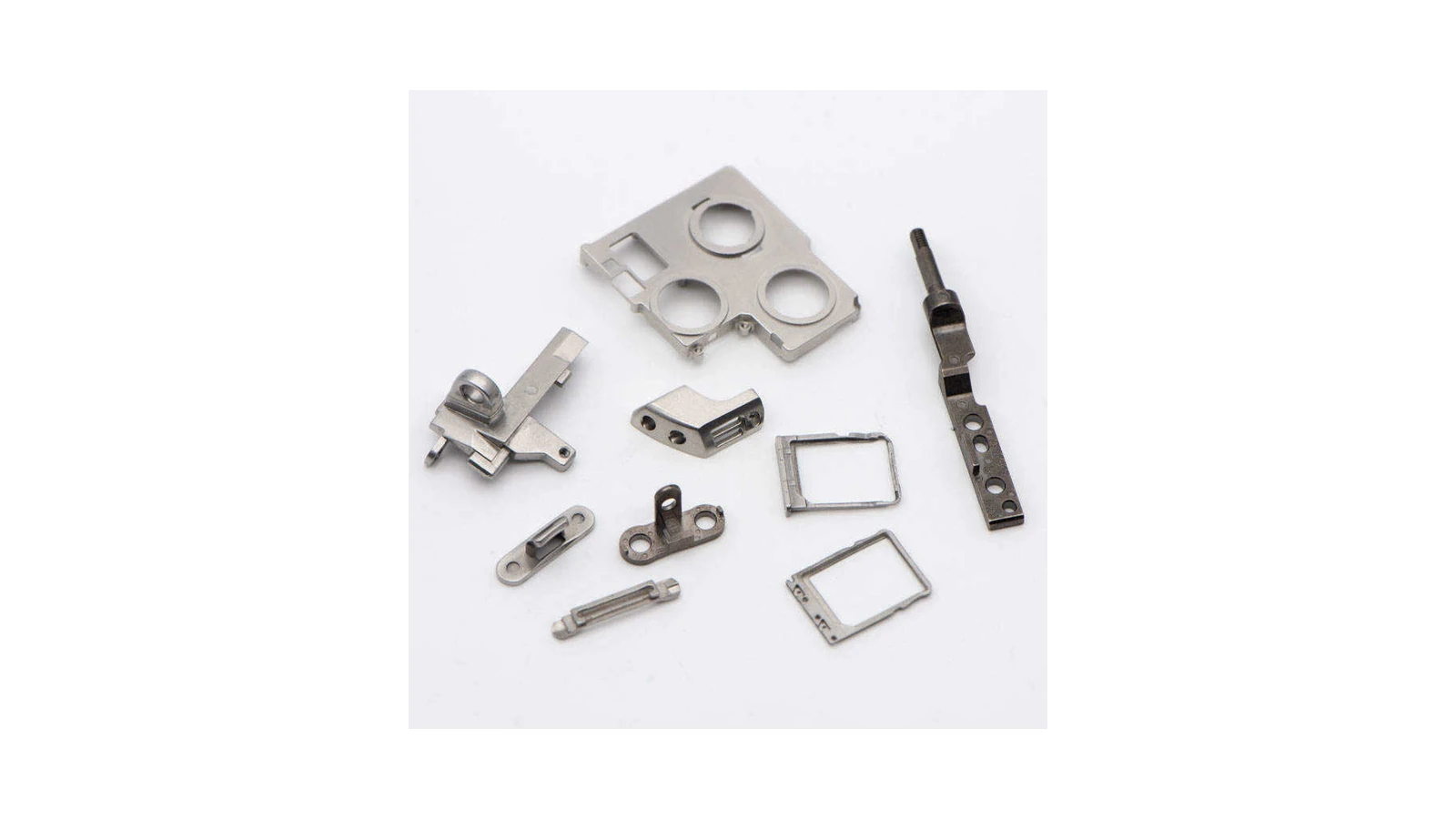
What These Real Parts Show Before You Judge MIM Suitability
These representative components show the kind of compact frames, supports, brackets, rings, and miniature mechanisms that make MIM worth evaluating in consumer electronics. The useful question is not whether your part looks identical, but whether the design combines integrated geometry, functional mating features, surface requirements, and repeat production demand.
Which Consumer Electronics Part Types Are Common MIM Candidates?
Consumer electronics MIM opportunities appear across several part groups, including phone and tablet hardware, laptop mechanisms, audio device components, camera module hardware, connector supports, and miniature mechanisms. The part group helps identify the likely engineering risks, but final MIM suitability still depends on geometry, material, annual volume, surface requirements, tolerances, and assembly function.
| Part Group | Typical Parts | Why MIM May Fit | Main Review Risk |
|---|---|---|---|
| Phone and tablet parts | SIM trays, camera rings, buttons, small internal brackets | Small size, cosmetic surfaces, repeat production | Visible surface zones, assembly tolerance, finishing route |
| Laptop parts | Hinge-related parts, retainers, support brackets, locking parts | Strength, compact mechanism, repeated movement | Wear, torque, dimensional repeatability |
| Audio device parts | Earbud metal frames, charging case inserts, miniature supports | Small geometry, appearance, assembly fit | Thin walls, polishing allowance, coating route |
| Camera module parts | Camera rings, support frames, miniature housings | Precision, appearance, compact structure | Roundness, flatness, coating compatibility |
| Connector and module hardware | Retainers, supports, miniature brackets | Dense features, repeat assembly | Burr control, plating, fit with mating parts |
| Miniature mechanisms | Latches, pivots, locking parts | Complex geometry and movement | Friction, wear, mating dimensions |
A common mistake is to treat every small metal component in an electronic product as a MIM candidate. MIM is usually more valuable when the part has three-dimensional complexity, internal or external features, holes, slots, ribs, steps, undercuts, or integrated functions that would require several machining or assembly operations by other methods.
For connector-related parts, the route must be defined carefully. MIM is generally more relevant for structural supports, retainers, housings, frames, and miniature brackets than for flat terminals, spring contacts, or thin stamped conductive parts. If electrical conductivity, elastic deflection, or spring behavior is the main function, the design should be reviewed against stamping, forming, material temper, and plating requirements before assigning the part to MIM.
Consumer Electronics MIM Parts by Device Type
Device type helps identify the operating environment and the most likely engineering risks. A phone part may be driven by appearance and assembly fit, while a laptop mechanism may be driven by movement, wear, and dimensional stability. The device context narrows the review, but the final manufacturing decision still depends on geometry, material, tolerance, surface finish, production volume, and DFM feasibility.
Mobile Phone and Tablet MIM Parts
Typical parts include SIM trays, camera rings, side buttons, internal brackets, connector supports, and small mechanism components. The main review points are visible surface zones, coating or polishing route, mating features, critical dimensions, and repeatability at production volume.
Laptop MIM Parts
Typical parts include hinge-related components, retainers, locking structures, brackets, shafts, pins, and support parts around mechanical or display assemblies. The main review points are repeated movement, wear, dimensional stability, and controlled fit with mating components.
Audio and Earbud MIM Parts
Typical parts include miniature frames, charging-case inserts, supports, latches, decorative structural pieces, and compact internal components. The main review points are thin geometry, cosmetic finish, assembly fit, coating allowance, and distortion risk.
Camera Module and Optical Device Parts
Typical parts include camera rings, small housings, positioning frames, support brackets, and cosmetic metal rings. The main review points are roundness, flatness, positioning accuracy, visible surface quality, and coating compatibility.
For smartphone or tablet camera hardware, also review the Mobile Phone MIM Parts guidance.
Connector and Module Hardware
MIM is most relevant for structural supports, retainers, housings, miniature brackets, locking parts, and alignment features. Flat terminals, spring contacts, and conductive elastic parts usually require a different review because conductivity, elastic deflection, material temper, and plating can dominate the manufacturing decision.
Miniature Mechanisms
Latches, pivots, locking parts, hinge segments, shafts, pins, and rotating elements should be classified by their real function: movement, wear, support, alignment, or dimensional stability. That function determines the most useful engineering review path.

Camera and Optical Frames
Representative real camera-related MIM frames and rings. Parts in this category can combine visible surfaces, roundness, positioning features, thin sections, and coating requirements, so cosmetic and dimensional review should be completed before tooling.
For parts with visible surfaces or locating features, critical dimensions, cosmetic zones, and finish requirements should be defined on the drawing before tooling.
Cross-Device MIM Part Families and Their Engineering Focus
Device type tells you where the component is used; part family tells you what the component must do. This distinction matters because the same hinge, bracket, shaft, or pin problem can appear in phones, laptops, wearables, cameras, and other compact electronic assemblies.
MIM Hinge Parts
Review MIM hinge design when the main problem is pivot fit, torque, friction, wear, repeated movement, or mating geometry in a compact mechanism.
MIM Bracket Parts
Review MIM bracket design when the part controls internal support, mounting position, load path, alignment, or repeatable assembly rather than movement.
MIM Shafts and Pins
Review MIM shafts and pins when the component includes shoulders, flats, grooves, heads, locking surfaces, or other integrated features beyond a simple cylindrical pin.
If the Main Risk Is Performance Rather Than Part Type
Some projects are easier to classify by the engineering risk than by the device or part name. Use these paths when one requirement dominates the feasibility review.
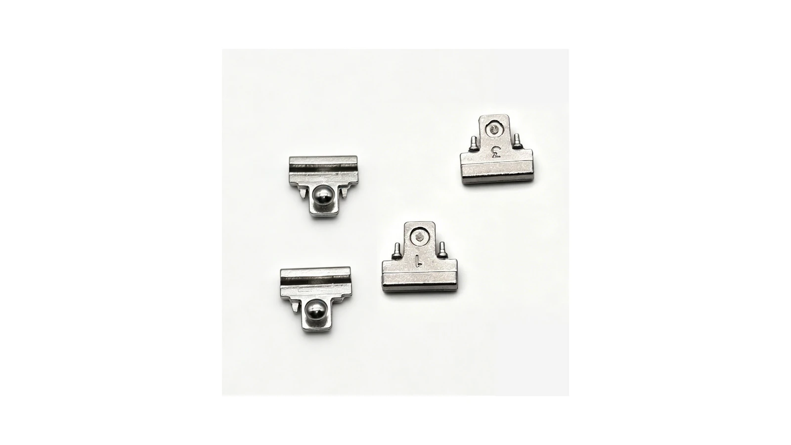
Representative real hinge components show why part-family review matters across consumer electronics: pivot geometry, locating features, contact areas, wear surfaces, and mating dimensions can be more important than the device name itself.
| Main Engineering Concern | Most Useful Next Review | Why |
|---|---|---|
| Tight assembly tolerance or dimensional stability | High Precision MIM Parts | Focuses the review on critical dimensions, datum strategy, sintering variation, inspection, and possible secondary machining. |
| Sliding, rotating, or friction-contact surfaces | Wear-Resistant MIM Parts | Shifts the discussion to material, hardness, contact surface, lubrication assumptions, wear, and mating-part behavior. |
| Sweat, moisture, or corrosion exposure | Corrosion-Resistant MIM Parts | Helps review material family, surface treatment, environment, and corrosion-related acceptance requirements. |
| Unclear whether MIM is the right process | Submit the drawing for engineering review | A drawing-based review can compare geometry, material, tolerance, finish, volume, and competing manufacturing routes before tooling. |
Is MIM the Right Fit for Your Consumer Electronics Part?
MIM is most valuable when a consumer electronics part combines compact metal geometry, three-dimensional complexity, repeat production, and functional or cosmetic requirements that would otherwise require multiple machining, forming, or assembly steps. The same review should also identify cases where another manufacturing route is more practical.
| Project Signal | Fit Decision | Engineering Reason | What to Review Next |
|---|---|---|---|
| Small metal part with complex 3D geometry, holes, ribs, slots, bosses, steps, or integrated features | Strong MIM candidate | Tooling can form geometry that may otherwise require multiple machining or assembly operations. | Tooling access, wall transitions, gate location, shrinkage, and sintering support. |
| Repeat production with stable design and meaningful annual volume | Strong MIM candidate | Tooling and process-development cost can be distributed across repeat production. | Annual volume, product lifecycle, tooling payback, and production validation plan. |
| Cosmetic surface plus functional or assembly requirements | Suitable, but needs early review | Gate marks, parting lines, polishing, coating, and dimensional change can affect both appearance and fit. | Visible zones, finish route, mating surfaces, critical dimensions, and inspection criteria. |
| Very tight local tolerance or precision mating feature | Needs process and secondary-operation review | As-sintered capability may not be sufficient for every local feature. | Critical-to-function dimensions, datum strategy, inspection method, and whether secondary machining is required. |
| Large, simple housing or thick uncomplicated geometry | Usually not a strong MIM fit | MIM tooling and sintering control may not provide enough advantage for simple large geometry. | Compare die casting or CNC machining. |
| Flat sheet-like part, spring contact, terminal, or conductive elastic feature | Usually not a strong MIM fit | Sheet forming, spring behavior, conductivity, or temper control may dominate the design. | Compare stamping, forming, material temper, and plating requirements. |
| Very low-volume prototype or design still changing | Usually not economical for MIM tooling yet | Tooling payback and design-change risk are high before the geometry stabilizes. | Consider CNC machining or additive manufacturing for validation first. |
For a broader explanation of the manufacturing route, review the Metal Injection Molding process.
Material and Function Mapping for Consumer Electronics MIM Parts
Material choice should be reviewed together with part function, finish route, tolerance plan, and use environment. An early material-to-function mapping helps engineers avoid selecting an alloy family before the actual corrosion, wear, strength, magnetic, cosmetic, and post-processing requirements are clear.
| Function or Requirement | Common MIM Material Direction | What to Review Before Tooling |
|---|---|---|
| Cosmetic metal surfaces, moisture exposure, or corrosion concern | Stainless steel families are often reviewed first when corrosion resistance and appearance are important. | Visible zones, polishing allowance, passivation, PVD, plating compatibility, edge rounding, and dimensional change after finishing. |
| Internal support, locking, or load-bearing miniature structures | Stainless steel or low alloy steel may be reviewed depending on strength, heat treatment, corrosion, and finishing needs. | Load path, datum structure, mating faces, heat treatment distortion, secondary machining, and inspection dimensions. |
| Sliding, pivoting, or friction-contact mechanisms | Wear-resistant alloy choices or heat-treated material routes may be considered after reviewing mating parts and movement conditions. | Contact surface, lubrication assumptions, hardness target, shaft or pin fit, wear testing plan, and post-sintering operations. |
| Magnetic response, sensor area, or electrical-related assembly | Material selection must be reviewed carefully because not every metal part near an electronic module has the same magnetic or electrical requirement. | Magnetic behavior, conductivity requirement, contact function, nearby sensors, plating, and whether MIM is the correct route. |
| High-visibility decorative plus structural function | The material route should be selected together with the final surface finish instead of being chosen only by strength. | Gate position, parting line, ejector marks, finishing allowance, coating adhesion, cosmetic inspection zones, and assembly fit. |
For detailed material families and grade-level selection, continue to MIM Materials. For parts where tolerance is the main issue, the better follow-up may be High Precision MIM Parts.
What Engineering Risks Should Be Reviewed Before Tooling?
Before a consumer electronics part is tooled for MIM, the engineering review should focus on the failure modes that affect appearance, assembly, function, and yield. These risks are often easier to correct before tooling than after trial production.
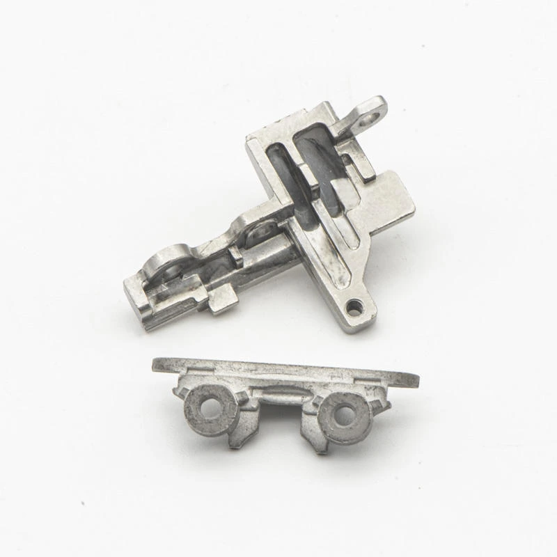
Real compact mechanism parts can combine thin sections, holes, slots, mating surfaces, and movement-related features in a small envelope. These areas should be reviewed for shrinkage, distortion, critical dimensions, finish, and assembly fit before tooling.
Visible Surface and Cosmetic Zone Planning
Consumer electronics parts often include visible surfaces, polished areas, plated areas, coated areas, or decorative metal features. If the visible zone is not defined early, the tooling and process team may place gates, parting lines, ejector marks, or finishing allowances in areas that later become cosmetic defects.
- Which surfaces are visible after final assembly?
- Can gate marks be placed in a non-visible area?
- Is polishing required before plating, PVD, passivation, or coating?
- Will finishing change edge sharpness or local dimensions?
Thin Wall, Small Feature, and Sintering Distortion Risk
MIM uses feedstock made from fine metal powder and binder, injected into tooling, then debound and sintered. Because sintering shrinkage must be compensated in tooling and process control, thin walls, uneven wall sections, long narrow features, and unsupported areas can increase distortion risk.
- Thin walls or long unsupported sections.
- Sudden section changes.
- Small holes, slots, ribs, bosses, and undercuts.
- Surfaces that may need sintering support.
Assembly Tolerance and Mating Part Fit
Consumer electronics parts are often assembled into compact spaces. A small dimensional shift can affect hinge movement, camera alignment, connector support, button feel, or enclosure fit. The tolerance strategy must separate critical-to-function dimensions from non-critical dimensions.
- Critical mating surfaces.
- Hole and slot functions.
- Datum references.
- Fit with pins, screws, shafts, plastic parts, or other metal parts.
Material and Surface Finish Compatibility
Material choice should be reviewed together with function, surface finish, and environment. Consumer electronics parts may require corrosion resistance, wear resistance, strength, cosmetic finishing, or magnetic behavior. Surface finish planning should happen before tooling.
Representative Engineering Scenarios
The following representative scenarios illustrate common review problems in consumer electronics MIM projects. They are composite engineering examples, not named customer cases or confidential project records.
Cosmetic Camera Ring Rework
What problem occurred: A small camera ring passed basic shape review but later showed visible surface inconsistency after polishing and coating, especially near a gate-related area that became visible after final assembly.
Why it happened: The visible surface zone had not been clearly defined before tooling review.
What the real system cause was: The project review focused too heavily on part shape and not enough on final assembled appearance, gate restriction, parting line expectation, and finishing allowance.
How it was corrected: The team reviewed visible and hidden zones, adjusted the tooling and finishing plan where possible, and defined cosmetic inspection areas separately from hidden functional surfaces.
How to prevent recurrence: Define cosmetic zones, gate restrictions, parting line expectations, polishing allowance, and final finish requirements before tooling approval.
Laptop Mechanism Fit Issue
What problem occurred: A compact laptop mechanism part assembled correctly during early samples but showed inconsistent movement after repeated assembly checks around a pivot-related feature.
Why it happened: The drawing controlled several general dimensions but did not clearly define which mating surfaces and pivot-related dimensions were critical to movement.
What the real system cause was: The tolerance strategy did not reflect the actual mechanism function, contact surface, wear area, and inspection priority.
How it was corrected: The team redefined datum references, identified pivot and mating surfaces, adjusted inspection focus, and reviewed whether selected areas required secondary operation.
How to prevent recurrence: Identify the movement path, contact surfaces, pin or shaft fit, wear areas, and functional inspection dimensions before tooling.
DFM Review Workflow for Consumer Electronics MIM Parts
A proper review should not only ask whether the part can be molded. It should check whether the part can be molded, debound, sintered, finished, inspected, and assembled with stable results.

What Information Should You Prepare for a Consumer Electronics MIM Parts Review?
If you already have a part drawing, the most useful next step is a project-level review. A good review is not only about whether the shape can be molded. It should evaluate material suitability, tooling risk, shrinkage behavior, cosmetic requirements, tolerance strategy, secondary operations, and inspection expectations. You do not need every detail to start the first screening; a 2D drawing, 3D CAD file, material direction, and estimated annual volume are usually enough for an initial feasibility review.
Send Your Consumer Electronics Part Drawing for MIM Review
Contact XTMIM if your project involves a small metal component with complex geometry, cosmetic surfaces, tight assembly fit, repeated movement, wear exposure, corrosion requirements, or unclear manufacturability before tooling. Please provide 2D drawings, 3D CAD files, material requirements, tolerance requirements, surface finish needs, mating part information, estimated annual volume, prototype timeline, and application background if available.
The XTMIM engineering team can review process suitability, material selection, tooling risk, sintering shrinkage, tolerance strategy, cosmetic surface planning, secondary operation needs, inspection requirements, and production feasibility before tooling, trial production, or volume production planning.
FAQ About Consumer Electronics MIM Parts
What consumer electronics parts are suitable for MIM?
MIM is most suitable for small, complex metal parts that require fine features, repeat production, metal strength, and controlled assembly fit. In consumer electronics, examples may include camera rings, SIM trays, small brackets, hinge-related parts, retainers, compact supports, latches, and miniature mechanism components.
Is MIM suitable for mobile phone parts?
Yes, MIM can be suitable for selected mobile phone and tablet parts such as SIM trays, camera rings, side buttons, small internal brackets, connector supports, and compact mechanism parts. Phone-related MIM parts often require careful review of visible surfaces, coating route, assembly fit, and high-volume repeatability.
Can MIM be used for laptop hinge parts?
MIM can be used for some laptop hinge-related components, retainers, pivots, locking structures, and compact mechanical parts. The main review points are torque, wear, mating dimensions, material choice, and whether any areas require secondary operation.
Are MIM parts suitable for connector terminals or electrical contacts?
Not usually as the first choice. MIM is more suitable for structural connector hardware such as retainers, housings, supports, miniature brackets, or locking features. Flat terminals, spring contacts, and conductive elastic parts often need stamping, forming, material temper control, and plating review instead of MIM.
Is MIM suitable for visible cosmetic parts?
MIM can be used for visible cosmetic metal parts, but the visible surface zone must be reviewed before tooling. Gate location, parting line, ejector marks, polishing allowance, plating, PVD coating, passivation, and inspection criteria can affect final appearance.
When is CNC better than MIM for consumer electronics parts?
CNC machining may be better for very low-volume prototypes, early design validation, large simple parts, or parts with extremely tight local tolerances that are not suitable for as-sintered MIM. CNC may also be more practical when the product design is still changing and MIM tooling cannot yet be justified.
What information should I send for a consumer electronics MIM part review?
Send 2D drawings, 3D CAD files, material requirements, critical tolerances, visible surface zones, finish requirements, mating part information, estimated annual volume, application environment, and current manufacturing method if available.