
Medical MIM Parts
XTMIM reviews custom endoscope-related MIM components from customer drawings, including small jaws, biopsy forceps components, articulation links, compact drive blocks, guide-channel components, locking parts and pivot-feature parts. Engineering review covers geometry, material direction, surface and edge requirements, critical dimensions, secondary operations, inspection needs and production volume before tooling or trial production.
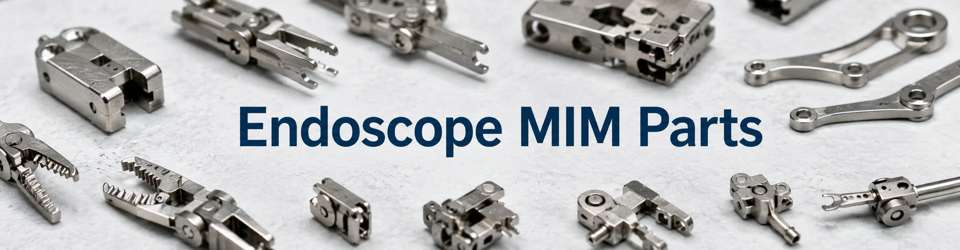
Quick answer: Endoscope MIM parts are small precision metal components used inside endoscopic or minimally invasive device mechanisms. They are usually reviewed for MIM when the part combines compact size, complex three-dimensional geometry, thin sections, small holes, slots, guide features, mating surfaces or functional edges. This page focuses on component-level MIM manufacturability and RFQ review, not endoscopy market trends, complete endoscope systems or medical device certification.
Visual disclosure: The hero, component-group, material-selection, DFM and inspection images on this page are representative illustrations used to explain component types and review points. They are not presented as named customer parts, production records or device-validation evidence.
Small jaws, biopsy forceps components, articulation links, drive blocks, guide parts and pivot-feature components.
Custom production starts from 2D drawings, 3D CAD, material notes, CTQ dimensions and application requirements.
Candidate stainless steels may include 17-4 PH, 420, 316L or 440C depending on function and validation needs.
Geometry, tolerance, surface finish, edge condition, secondary operations, annual volume and inspection strategy.
Manufacturing and regulatory boundary: XTMIM can review component-level MIM manufacturability, material feasibility, DFM risk, secondary operations and inspection planning. Final medical device approval, biological evaluation, cleaning validation, sterilization validation, labeling and regulatory submission remain the responsibility of the device owner or qualified medical device manufacturer.
Endoscope MIM Parts We Can Support
XTMIM reviews custom metal components used in grasping, biopsy, articulation, motion-transfer, guide-channel and pivot assemblies. Production is based on customer drawings and engineering requirements; the scope does not include complete endoscope systems or branded replacement parts.

The visual explains candidate component types and does not represent a named customer project or a validated medical device.
Typical Endoscope MIM Component Groups
The table summarizes component groups commonly evaluated before detailed DFM, material, tolerance and inspection review.
| Part Group | Representative Parts | Typical Structure | Common Material Direction | Custom Review Focus |
|---|---|---|---|---|
| Grasper and biopsy components | Small jaws, cup components, forceps heads | Teeth, thin lips, cup geometry, pivot holes | 420, 17-4 PH or 316L depending on function | Jaw alignment, burr control, edge condition, paired inspection |
| Articulation components | Links, connectors, lock bars | Thin arms, small holes, slots, compact link geometry | 17-4 PH or 420 candidates | Sintering distortion, hole position, load direction, fatigue-sensitive zones |
| Drive and locking parts | Drive blocks, lock blocks, sliders | Guide slots, shoulders, contact faces, compact block features | 17-4 PH, 420 or other stainless steel candidates | Slot accuracy, wear zones, mating surfaces, secondary machining need |
| Guide-channel components | Knife guides, guide blocks, channel supports | Narrow channels, contact edges, guide surfaces | 420 or 440C candidates where hardness is important | Edge finish, slot control, burr limits, inspection access |
| Pivot-feature parts | Small pivot parts, pin-interface components, rotating features | Small holes, bosses, circular interfaces, alignment features | Stainless steel candidates based on load and corrosion needs | Hole roundness, pin fit, reaming allowance, functional gauge planning |
A MIMA endoscopic device parts case study documents MIM articulation lock bars, articulation connectors, articulation drive blocks and knife guides using stainless steel MIM materials such as 17-4 and 420. This supports the real application basis for endoscope MIM components, although each commercial project still requires drawing-level review.
Representative Structures and Custom Features
Endoscope-related parts are usually evaluated for MIM when compact geometry, integrated features or repeat-production requirements make full machining less efficient. Review focuses on the actual geometry, functional surfaces, mating requirements and planned production route.
Small Jaws and Cup Features
Used in grasping or biopsy-related mechanisms. Review points include thin lips, teeth, cup geometry, jaw closing alignment, pivot holes and burr-sensitive edges.
Thin Articulation Links
Used for motion transfer in compact mechanisms. Review points include thin arms, hole patterns, load direction, shrinkage movement and sintering support strategy.
Compact Drive Blocks
Used to transfer force or motion. Review points include guide slots, shoulders, contact surfaces, secondary machining allowance and wear-related material selection.
Guide-Channel Features
Used to guide small moving parts or cutting-path elements. Review points include slot width, edge condition, surface finish, burr control and inspection access.
Pivot Holes and Pin Interfaces
Used for rotation or assembly alignment. Review points include hole roundness, pin fit, datum strategy, reaming need and functional gauge planning.
Locking and Contact Features
Used in compact locking, sliding or positioning functions. Review points include parting line location, gate mark position, contact wear and surface finishing route.
Material and Surface Finish Options for Endoscope MIM Components
Material selection for endoscope MIM parts should start from component function rather than a generic “medical grade” label. Strength-driven blocks, wear-sensitive guides and corrosion-focused components may require different stainless steel routes. The table below provides candidate directions for drawing-level RFQ review.

Strength, wear, hardness and corrosion requirements should be reviewed together with geometry, heat treatment and finishing needs.
For broader material comparison, review MIM materials and MIM stainless steel material options.
Material review note: Candidate grades must be confirmed against load, hardness, corrosion exposure, mating surfaces, heat treatment, finishing and device-level requirements.
| Requirement | Candidate Material Direction | Typical Review Point | Related Material Page |
|---|---|---|---|
| Strength-driven links or blocks | 17-4 PH stainless steel | Heat treatment, dimensional change, corrosion expectation and distortion risk | 17-4 PH MIM stainless steel |
| Hardness or contact surfaces | 420 stainless steel | Edge stability, wear, corrosion trade-off and finishing route | 420 MIM stainless steel |
| Corrosion-focused components | 316L stainless steel | Lower hardness, wear limitation, ductility and corrosion exposure | 316L MIM stainless steel |
| Higher wear or hardness needs | 440C stainless steel | Brittleness risk, edge chipping, sliding contact and corrosion review | 440C MIM stainless steel |
Common Surface Finish and Post-Processing Directions
Surface finish and post-processing should be defined according to the component function. MIM can form the complex base geometry, but selected surfaces may still require secondary operations to meet assembly, motion, edge or corrosion requirements.
| Requirement | Possible Operation | When It May Be Needed |
|---|---|---|
| Pivot hole fit | Reaming, drilling or sizing | When hole roundness, position or pin fit is critical to movement |
| Jaw or guide edge condition | Deburring, polishing or edge control | When edges contact mating parts, grip surfaces or guide movement |
| Corrosion-focused surfaces | Passivation or surface cleaning route | When customer specifications require corrosion-related surface treatment |
| Strength or hardness adjustment | Heat treatment where suitable | When the selected material and part geometry allow heat treatment review |
Application Direction and Custom Project Fit
Endoscope MIM components may be reviewed for different mechanism directions. The application background helps the engineering team understand whether the component is load-bearing, wear-sensitive, corrosion-sensitive, edge-sensitive or mainly used for positioning and motion transfer.
Small jaws, cup components and biopsy forceps-related parts where jaw alignment, edge condition and pivot fit matter.
Thin links, connectors and compact movement-transfer parts where distortion, hole position and support strategy matter.
Drive blocks, lock blocks and sliders where slots, contact surfaces, wear and secondary machining may need review.
Guide components and knife guide features where slot width, edge control, burr limits and finish requirements matter.
For broader medical component categories, review the medical MIM parts overview. For requirement-based pages, see high-precision MIM part requirements, wear-resistant MIM part review and corrosion-resistant MIM part review.
Send Drawings for Endoscope MIM Part Review
If your endoscope component includes small jaws, biopsy forceps features, articulation links, drive blocks, guide channels, pivot holes, thin arms, narrow slots or functional edges, XTMIM can review the drawing for MIM manufacturability before tooling.
Please provide 2D drawings, 3D CAD files, material requirements, CTQ dimensions, tolerance requirements, surface finish expectations, edge or burr requirements, mating part information, estimated annual volume and application background.
Why These Endoscope Components May Fit MIM
MIM is useful for endoscope-related components when small size is combined with complex three-dimensional geometry. The process forms a molded green part from metal-powder feedstock, removes the binder through debinding and then sinters the component to final density and dimensions. Because sintering produces substantial shrinkage, tooling compensation, geometry balance and critical-dimension planning must be reviewed before tooling.
The EPMA overview of metal injection moulding describes MIM as a route for small complex parts and explains why simpler powder-metallurgy or machining routes may be more economical for less complex geometry. For endoscope-related components, process selection should therefore be based on geometry, production volume and the complete manufacturing route rather than part size alone.
Small Complex Geometry
Candidate components may combine pivot holes, thin arms, cup-shaped jaw geometry, guide slots, small teeth, compact three-dimensional surfaces and integrated locating or locking features. Review should consider internal features, wall transitions, parting lines, gate location and sintering support together.
Repeatable Production After Tooling
MIM becomes more attractive when the design is stable and annual demand can justify tooling. Early prototypes or frequently changing designs may be better served by CNC machining or additive manufacturing before committing to production tooling.
Reduced Machining for Difficult Features
MIM can form complex base geometry near net shape, while selected holes, slots, edges or contact surfaces may still require sizing, machining, polishing, deburring or dedicated inspection.
Fit Compared with CNC or Stamping
MIM may be suitable when several machined or assembled features can be integrated into one small component and production volume supports tooling. Large, simple, low-volume or extensively post-machined parts may not justify the process.
Practical review question: Which features can be molded reliably, which features require post-sintering control, and does the combined route improve cost, repeatability or design integration compared with full machining?
DFM Risks Before Tooling
Endoscope-related MIM components should be reviewed before tooling because small design choices can affect mold filling, debinding stability, sintering shrinkage, distortion, burr formation and inspection repeatability. For a broader review route, see DFM for MIM.

This visual explains common feature-level review points and is not presented as a named customer component or production record.
Thin Arms and Long Slender Features
Thin arms are common in articulation links and small mechanical connectors. The main concern is dimensional movement during debinding and sintering, including bending, twisting or uneven shrinkage.
- Minimum wall section and transition areas.
- Gate position and flow path.
- Support direction during sintering.
- Fixture or setter requirement.
- Inspection datum strategy.
- Whether the feature is load-bearing or only locating.
Small Holes, Slots and Pivot Interfaces
Small holes and slots may be molded, machined, reamed or finished depending on tolerance and function. For additional design guidance, review MIM holes, slots and undercuts.
| Feature | Typical Risk | Review Before Tooling |
|---|---|---|
| Small pivot hole | Shrinkage variation, roundness, assembly fit | Hole size, datum and reaming allowance |
| Narrow slot | Width variation, distortion and burrs | Slot function and secondary-machining need |
| Long guide channel | Warpage and contact inconsistency | Support strategy, material and finishing |
| Cross-hole | Tooling complexity and flash risk | Mold action, parting line and inspection access |
| Paired hole pattern | Misalignment during assembly | Datum scheme and functional-gauge possibility |
Teeth, Edges and Cup-Shaped Features
The drawing should clarify whether an edge is used for cutting, gripping, alignment or clearance. Each function leads to a different molding, finishing and inspection route.
Undercuts, Parting Lines and Gate Location
Gate marks and parting lines should be kept away from critical sliding surfaces, jaw contact edges, pivot interfaces and other functional surfaces unless the effect has been reviewed.
Sintering Support and Distortion Risk
Thin arms, asymmetric features and uneven mass distribution may move during sintering. The review should consider support orientation and setter strategy as well as moldability. See MIM sintering supports for geometry-specific guidance.
Tolerance, CTQ and Inspection Review
Critical dimensions should be separated from general dimensions according to assembly function. Pivot position, jaw alignment, slot width, mating surfaces and burr-sensitive edges may require different control methods. For general process boundaries, review MIM tolerances.

The image explains a dimensional-review context and is not presented as an actual customer inspection record or device-validation result.
Critical Dimensions Are Usually Assembly-Driven
Critical dimensions may include pivot-hole position, jaw spacing, slot width, mating-surface flatness, pin fit, guide-channel width or paired-component alignment. These requirements should be linked to the actual assembly function and inspection method.
| CTQ Feature | Why It Matters | Engineering Review |
|---|---|---|
| Pivot-hole position | Controls motion, alignment and pin fit | Datum strategy, reaming need, functional gauge or CMM inspection |
| Jaw-closing alignment | Affects gripping, sampling or closing function | Paired inspection, edge finishing and mating-part review |
| Slot width | Controls guide or drive fit | As-sintered capability versus secondary machining |
| Contact surface | Affects wear and motion transfer | Material, finishing, flatness and surface inspection |
| Burr-sensitive edge | Affects mating, movement and functional edge condition | Burr limit, polishing route, visual criteria and drawing clarity |
Edge Radius, Burr Control and Contact Surfaces
The drawing should define whether an edge must remain sharp, be broken, polished, radiused or controlled to a functional burr limit. A general “no burr” note is usually less useful than identifying the surfaces and interfaces where burrs affect function.
Surface Finish and Cleaning-Related Geometry
Surface condition can affect assembly, motion and device-level cleaning considerations. XTMIM can review surface-finish feasibility, while final cleaning and sterilization requirements remain part of device-level validation.
Secondary Machining, Finishing and Post-Processing
MIM can form the complex base geometry while selected CTQ areas receive secondary control. The need for post-processing does not by itself make a part unsuitable for MIM; the complete route should be evaluated for function, repeatability and cost.
| Feature or Requirement | Possible Secondary Operation | Reason for Review |
|---|---|---|
| Precision pivot hole | Reaming, drilling or sizing | Improves fit control when as-sintered tolerance is insufficient |
| Guide or drive slot | Machining, sizing or controlled finishing | Supports movement accuracy and mating-part clearance |
| Jaw or cup edge | Deburring, polishing or radius control | Reduces burr risk and improves edge consistency |
| Contact surface | Polishing, lapping or selected machining | Improves contact behavior, motion stability or wear-related surfaces |
| Corrosion-related surface | Passivation or customer-specified cleaning route | Must follow the customer specification and device-level requirements |
| Strength or hardness | Heat treatment where suitable | Requires review of material, geometry, distortion and final inspection |
When MIM May Not Be Suitable for Endoscope Components
MIM is not always the correct route. Unsuitable cases should be identified before tooling investment.
Very Low Annual Volume
For a few prototypes or uncertain early-stage samples, CNC machining, additive manufacturing or manual fabrication may be more practical.
Oversized or Simple Components
Large, simple, flat or easily machined parts may not justify MIM tooling and process complexity.
Extensive Full-Surface Machining
If most functional surfaces require precision machining after sintering, a machined or hybrid route may create more value.
Uncontrolled Thin or Sharp Features
Unsupported thin arms, sharp internal corners, abrupt wall transitions and fragile edges should be reviewed and modified before tooling.
Representative scenario disclosure: The following scenarios combine common DFM and trial-production risks. They are illustrative engineering examples, not named customer case studies, production records or medical-device validation results.
Representative Engineering Scenario: Articulation Link Distortion
Problem: A small articulation-link concept showed inconsistent hole alignment after sintering. The outer profile appeared acceptable, but the link did not assemble smoothly with its mating mechanism.
Cause: Thin arms, asymmetric mass distribution and small pivot holes near a transition zone were combined with weak functional-datum definition. The issue was therefore not limited to nominal hole diameter.
Engineering handling: Review the datum strategy, identify holes that require secondary finishing, evaluate sintering-support orientation and define functional surfaces before tooling.
Representative Engineering Scenario: Guide Slot and Edge Control
Problem: A guide-component concept included a narrow functional slot, but guide width, edge condition and burr requirements were not clearly separated.
Cause: The slot was treated only as a molded feature even though it also functioned as a guide and contact surface.
Engineering handling: Classify the slot as a CTQ feature, define edge and burr limits, review post-sintering finishing allowance and select the material route according to contact and wear requirements.
Endoscope MIM Part RFQ and Drawing Review Checklist
A complete RFQ package allows manufacturability, tooling, secondary-operation and inspection risks to be reviewed before trial production.
What to Provide for a DFM Review
| RFQ Input | Why It Matters |
|---|---|
| 2D drawing | Defines dimensions, tolerances, material and notes |
| 3D CAD file | Supports geometry, tooling, gate and shrinkage review |
| Material requirement | Guides feedstock and heat-treatment review |
| CTQ dimensions | Separates functional holes, slots, alignment features and mating faces from general dimensions |
| Surface and edge requirements | Supports polishing, deburring and inspection planning |
| Mating-part information | Supports fit, motion, clearance and contact-surface review |
| Annual volume and project stage | Helps determine tooling economics and the appropriate development route |
| Application background | Clarifies load, wear, corrosion, cleaning-related and documentation requirements |
What XTMIM Engineers Will Check
- Geometry, wall transitions and MIM suitability.
- Holes, slots, undercuts, gates and parting-line implications.
- Sintering support and critical-dimension risks.
- Material direction and secondary-operation needs.
- Inspection strategy for critical-to-function features.
Request an Endoscope MIM Component Review
Submit 2D and 3D files together with material, CTQ, tolerance, surface, edge, mating-part, annual-volume and application information for a drawing-level manufacturability review.
Medical Device Compliance and Validation Boundary
Endoscope-related MIM components may be used within medical devices, but component manufacturability review is not equivalent to finished-device approval. XTMIM can review geometry, material feasibility, tolerances, secondary operations, surface finishing and inspection planning.
The FDA guidance on reprocessing reusable medical devices addresses validation of cleaning, disinfection, sterilization and labeling instructions at device level. The FDA guidance on ISO 10993-1 biological evaluation places biological evaluation within a medical-device risk-management process.
Responsibility boundary: Final medical-device approval, biological evaluation, cleaning validation, sterilization validation, labeling and regulatory submission remain the responsibility of the device owner or qualified medical-device manufacturer.
Standards and Technical References
These references support the application, process-selection and regulatory boundaries discussed here. Project drawings, material specifications, risk management and regulatory review remain controlling.
| Reference | Relevance | Use Boundary |
|---|---|---|
| MIMA Endoscopic Device Parts Case Study | Documents endoscopic articulation and guide components manufactured by MIM. | Supports application relevance, not a universal material choice, performance guarantee or medical approval claim. |
| EPMA Metal Injection Moulding Overview | Explains MIM for small complex components and process-selection boundaries. | Supports manufacturing-route decisions rather than project-specific approval. |
| FDA Reprocessing Medical Devices Guidance | Addresses validation of device-level reprocessing instructions. | Does not certify a component or supplier. |
| FDA ISO 10993-1 Biological Evaluation Guidance | Explains biological evaluation within medical-device risk management. | Supports the device-level responsibility boundary. |
FAQ: Endoscope MIM Parts
Can MIM be used for endoscope grasper jaws?
Yes, MIM can be considered when the part combines small teeth, cup geometry, pivot holes, curved surfaces or integrated features. Jaw alignment, edge condition, burr control, material selection and critical secondary finishing must be reviewed.
What endoscope components are commonly suitable for MIM?
Candidate parts include grasper jaws, biopsy forceps components, articulation links, connectors, drive blocks, guide components, locking parts and small pivot features. Suitability depends on geometry, tolerance, material, volume and inspection requirements.
Which stainless steels are used for endoscope MIM parts?
Possible candidates include 17-4 PH, 420, 316L and 440C depending on strength, hardness, wear and corrosion requirements. Final selection must follow the drawing and device-level requirements.
Can MIM achieve tight tolerances for pivot holes and slots?
MIM can form small holes and slots, but tight functional tolerances may require reaming, sizing, machining or dedicated inspection. CTQ features should be identified before tooling.
Do endoscope MIM parts require secondary machining?
Some non-critical features may remain as-sintered, while critical holes, slots, guide surfaces, contact faces or edges may require secondary machining or finishing.
Is MIM suitable for low-volume endoscope prototypes?
MIM is usually not the first choice for very low-volume prototypes because tooling is required. CNC machining or additive manufacturing may be more practical during early design iteration.
Who is responsible for medical-device validation and biocompatibility testing?
The device owner or qualified medical-device manufacturer is responsible for device-level validation, biological evaluation, cleaning validation, sterilization validation and regulatory submission.
Does XTMIM provide medical-device certification for endoscope MIM parts?
No. XTMIM supports component manufacturability, material feasibility, secondary-operation and inspection review. Final device certification and regulatory approval remain the responsibility of the device owner.
What information should I provide for an endoscope MIM part quotation?
Provide 2D drawings, 3D CAD, material requirements, CTQ dimensions, tolerances, surface and edge requirements, mating-part information, annual volume and application background.