
MIM Parts · Micro Gears
Micro Gears for Metal Injection Molding
This page reviews whether compact metal pinions, spur gears, internal gear features, and gear-and-hub components are practical candidates for Metal Injection Molding. The engineering focus is tooth geometry, bore-to-tooth alignment, sintering control, inspection, and any targeted secondary operations required for repeat production.
Quick answer: MIM is best suited to small metal gears that combine detailed teeth with bores, hubs, shaft interfaces, recesses, or other integrated features at repeat production volumes. Machining or gear cutting is usually more practical for prototypes, frequent design changes, oversized gears, or projects that require extremely tight final tooth accuracy without post-sintering finishing.
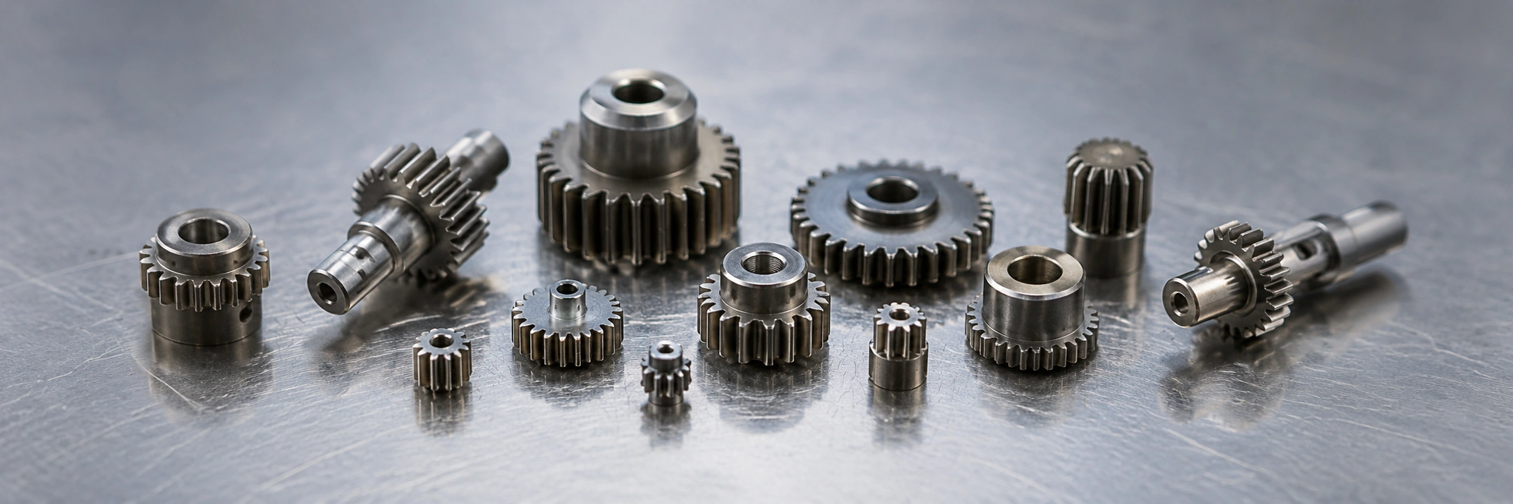
Image disclosure: Representative engineering illustration used to explain micro gear application fit. It is not presented as a specific customer project, production batch, or XTMIM manufacturing record.
What Are Micro Gears in MIM?
Here, micro gears means compact metal spur gears, pinions, internal gear features, and gear-and-hub or gear-and-shaft components whose teeth and integrated features are evaluated as one MIM part.
The manufacturing value comes from consolidating the tooth form with features such as a bore, stepped hub, shaft interface, recess, positioning detail, or side geometry in a near-net-shape component. Feasibility therefore depends on the complete design—including tooth root thickness, bore location, concentricity, section balance, sintering support, material, and inspection plan—not merely on whether the teeth can be molded.

Image disclosure: Representative engineering illustration. The forms are conceptual examples for design review and are not presented as actual customer parts or verified production samples.
When Are Micro Gears Good Candidates for MIM?
The following review separates projects that can benefit from a near-net-shape MIM route from those better served by machining, gear cutting, press-and-sinter PM, or another manufacturing method.
| Review Factor | Good Candidate for MIM | Higher Risk or Poor Fit |
|---|---|---|
| Part size | Small gear component with compact geometry | Large gear where MIM tooling and sintering control are less practical |
| Geometry | Gear teeth plus hub, bore, shaft, recess, undercut, or side features | Simple flat gear that can be cut or stamped more easily |
| Production volume | Repeat production where tooling can be justified | Very low-volume prototype or one-off repair part |
| Material need | Stainless steel, low-alloy steel, or other MIM-compatible metal | Plastic gear requirement or material not suitable for MIM feedstock |
| Accuracy expectation | Tolerances can be reviewed with tooling compensation, inspection, and possible secondary operations | Extremely tight final gear accuracy without post-sintering finishing |
| Functional risk | Moderate torque, alignment, or assembly requirements that can be validated | High-speed or high-load gear pair without complete engineering validation |
Engineering note: MIM parts shrink during sintering. Tooling must be designed with shrinkage compensation, and the process must control distortion, tooth consistency, bore location, and surface condition. If a drawing treats a micro gear exactly like a machined gear, the feasibility review may miss important process risks.
Micro Gear Design Features That Matter Before Tooling
A micro gear should be reviewed as both a gear and a molded metal component. The design team should not only check the module, tooth count, and outside diameter, but also the surrounding features that may affect molding, debinding, sintering, and inspection.
Gear Tooth and Root Features
Tooth profile consistency, root thickness, face width, and edge condition can influence engagement, durability, and inspection planning. The drawing should identify which tooth features are functional.
Bore, Hub, and Shaft Alignment
For many micro gears, the bore-to-tooth relationship is more important than the tooth shape alone. Bore tolerance, shaft fit, datum definition, and concentricity should be reviewed before tooling.
Design Review Checklist
- Tooth profile and tooth root thickness
- Gear outside diameter and face width
- Bore diameter and bore tolerance
- Hub height and wall thickness
- Shaft interface or press-fit area
- Concentricity between bore and teeth
- Thin sections near the gear root or hub
- Gate location sensitivity
- Flatness or runout requirement
- Whether sizing, machining, or finishing may be required
Functional Dimension Priority for Micro Gear Review
A practical MIM review should separate functional features from general reference geometry. This prevents the project from becoming over-constrained while still protecting the dimensions that control gear performance.
| Feature | Why It Matters | Review Priority |
|---|---|---|
| Bore and shaft fit | Controls assembly, rotation, and possible press-fit performance | High if the bore is the rotating datum or assembly interface |
| Tooth profile and tooth thickness | Affects meshing, backlash, contact behavior, and noise risk | High when the gear pair has defined transmission requirements |
| Concentricity between bore and teeth | Controls rotation stability and tooth engagement consistency | High when the gear rotates on a shaft or bearing surface |
| Hub height and wall thickness | Affects molding balance, sintering stability, and strength around the bore | Medium to high depending on load and assembly method |
| Non-functional outer features | May be less critical if they do not affect assembly or gear operation | Lower unless they control location, fit, or handling |
A common mistake is to ask whether “MIM can make the gear teeth” without reviewing the bore and alignment requirement. Before tooling, the project team should confirm which dimensions control performance. If every dimension is treated as critical, the quotation may become unrealistic. If critical features are not marked, the supplier may not know where secondary sizing, fixture support, or inspection priority should be focused.
For broader DFM context, users can also review the MIM design guide, but this page focuses only on micro gear application review.

Image disclosure: Representative engineering illustration used to explain drawing-review logic. It is not a customer drawing, approved tooling record, or documented XTMIM project.
Materials Commonly Considered for MIM Micro Gears
Material selection for MIM micro gears depends on the working environment, load condition, wear expectation, corrosion requirement, magnetic requirement, and any post-sintering treatment. The material should be selected for the function of the gear, not only for general strength.
| Material Direction | Typical Reason to Consider | Review Notes |
|---|---|---|
| Stainless steel | Corrosion resistance, clean appearance, general engineering use | Suitable when corrosion resistance matters more than high hardness |
| Low-alloy steel | Strength direction, possible heat-treatment requirement | Needs review of heat treatment, distortion, and final inspection needs |
| Wear-resistant material direction | Gear contact, sliding, or repeated engagement | Material and surface condition should be reviewed together |
| Soft magnetic material direction | Small gear-like rotor or magnetic assembly component | Only relevant when magnetic performance is part of the function |
| Surface finishing direction | Appearance, friction, corrosion, or assembly condition | Should be specified only when function requires it |
The material decision should be made before tooling because material behavior can influence shrinkage, sintering conditions, secondary operations, and final inspection planning. If the project only says “metal gear” without a material target, the supplier cannot properly evaluate strength, corrosion, wear, or processing risk.
Material review note: For micro gears, material selection should be connected to the working environment and functional load. A corrosion-resistant gear, a wear-contact gear, and a gear-like magnetic component may look similar in size, but they may require different material and post-sintering review paths.
Manufacturing and Quality Risks in MIM Micro Gears
Micro gears require careful review because small geometry does not automatically mean easy production. The smaller the gear tooth and bore relationship becomes, the more important it is to control molding consistency, sintering support, and inspection method. For broader guidance on fine teeth, small bores, demolding, sintering distortion, and measurement access, review the Micro MIM process limits for fine teeth and small bores.
| Risk Area | Why It Matters | Review Action |
|---|---|---|
| Tooth profile variation | Tooth engagement, noise, and transmission behavior may be affected | Define which tooth features are functional and how they will be checked |
| Tooth root weakness | Thin roots may be sensitive during molding, handling, or service | Review tooth root thickness and material direction |
| Bore accuracy | Bore position often controls gear rotation and assembly | Confirm bore tolerance, shaft fit, and whether post-sintering sizing is needed |
| Concentricity | Gear teeth must align with the rotating axis | Mark functional datum and inspection requirement |
| Sintering distortion | Thin or uneven sections may distort during sintering | Review part support, section balance, and geometry symmetry |
| Surface condition | Gear engagement and assembly may be affected | Confirm whether finishing, polishing, heat treatment, or coating is required |
| Edge damage | Small teeth can be sensitive during handling and finishing | Review packaging, deburring, and inspection expectations |
When Secondary Operations May Be Needed
MIM can produce near-net-shape micro gears, but some projects still need targeted post-sintering operations. The decision should be based on function, not on a general assumption that every micro gear needs machining.
| Requirement | Possible Secondary Operation | Why It May Be Needed |
|---|---|---|
| Tight bore fit or shaft alignment | Sizing, reaming, or selective machining | To improve fit consistency where the bore is a functional datum |
| Higher strength or wear requirement | Heat treatment or material-specific post-processing | To support load, wear, or fatigue-related requirements when applicable |
| Surface condition requirement | Polishing, deburring, finishing, or coating review | To manage contact surface, appearance, friction, or corrosion behavior |
| Critical tooth engagement | Inspection-driven sorting or selective finishing | To control functional tooth features when the gear pair is sensitive |
MIM can support repeatable production, but it should not be treated as a process that automatically delivers final precision for every micro gear design. Critical gear projects may require secondary operations such as sizing, bore finishing, heat treatment, surface finishing, or selective machining after sintering. Where bore accuracy, concentricity, and final inspection planning dominate the project risk, the review logic may also overlap with high precision parts, while this page remains focused on micro gears.
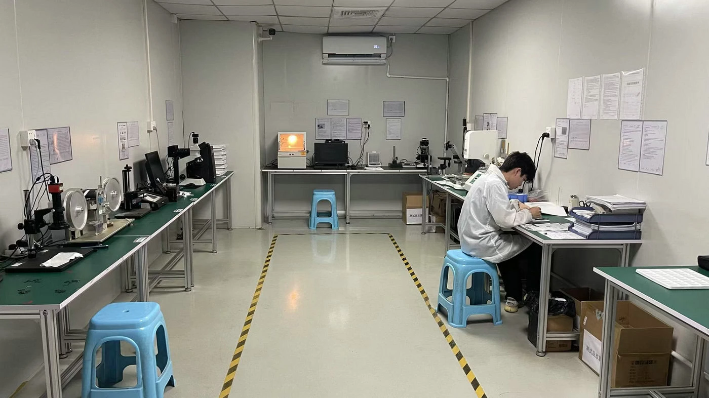
Image disclosure: Verified real XTMIM inspection workshop photograph. It documents general inspection capability and is not presented as a specific micro gear customer project or inspection record.
MIM Micro Gears vs Machined or PM Gears
MIM should be compared with machining, gear cutting, and PM according to geometry, production volume, material, tolerance, and post-sintering requirements. The table below provides only the process boundaries needed for a micro gear decision.
| Process Route | Better Fit | Main Limitation |
|---|---|---|
| MIM | Small metal gears with complex 3D features and repeat production volume | Tooling investment and sintering-related dimensional review are required |
| Machining / gear cutting | Prototypes, low volume, very tight final tooth accuracy, or frequent design changes | Unit cost may rise when small complex features repeat in volume |
| PM press-and-sinter | High-volume, more regular gear shapes with compaction-friendly geometry | Uniaxial compaction limits complex side features and undercuts |
| Hybrid route | MIM blank plus selective sizing, machining, or finishing | Requires clear identification of critical features |
The decision is usually not “MIM or machining” in a simple way. For some micro gears, MIM may produce the near-net-shape body while a secondary operation controls a critical bore or functional surface. This hybrid thinking is often more realistic than expecting one process to solve every requirement.
Representative Engineering Scenario
Scenario disclosure: This representative scenario combines common micro gear review conditions for engineering explanation. It is not presented as a specific customer project, quotation, production record, or verified field case.
A small pinion gear is being reviewed for repeat production. The design includes a central bore, a short hub, fine gear teeth, and a side positioning feature. The available 3D model does not identify the functional datum, bore fit, torque requirement, or inspection method.
From a MIM review perspective, the part may be a good candidate because it is small, metal, and geometrically detailed. However, the project cannot be quoted accurately until the team confirms which features are critical. If the bore controls rotation, it may need tighter inspection or post-sintering sizing. If the gear teeth are the most critical feature, the tooth profile and inspection method must be discussed before tooling. If annual volume is too low, machining may be more practical during early validation.
This type of review prevents the project from being judged only by appearance. It connects geometry, function, material, inspection, and production volume before tooling begins.
What to Send for a Micro Gear MIM Review
A useful RFQ package for MIM micro gears should include enough information to evaluate geometry, process risk, material, and inspection requirements. Early-stage projects can still be reviewed, but production quotations require clearer functional and dimensional inputs.
Drawing and Geometry
- 3D CAD file
- 2D drawing with functional dimensions
- Gear module or tooth geometry information
- Tooth count, outside diameter, face width, and bore size
Function and Inspection
- Bore fit or shaft interface requirement
- Load, torque, wear, or rotation condition if known
- Critical datum and concentricity requirement
- Inspection method or acceptance criteria if already defined
Material and Production
- Required material or working environment
- Surface finish or coating expectation
- Heat treatment requirement if applicable
- Annual volume and expected production stage
Early Feasibility Review vs Production RFQ
| Review Stage | Minimum Useful Inputs | Expected Output |
|---|---|---|
| Early feasibility review | 3D model, approximate size, material direction, functional concern, expected volume range | Initial judgment on whether MIM is worth further evaluation |
| DFM review before tooling | 2D drawing, critical dimensions, datum, tooth and bore requirements, material target | Manufacturing risk review and secondary operation discussion |
| Production RFQ | Final drawing, annual volume, inspection plan, surface / heat treatment needs, packaging or assembly requirements | More accurate quotation, tooling review, and production planning basis |
If the drawing is still early, the project can still be reviewed. In that case, the goal should be feasibility feedback rather than a final production quote. The more clearly the functional features are marked, the easier it is to judge whether MIM, machining, PM, or a hybrid route is more appropriate.

Image disclosure: Representative engineering illustration used to explain RFQ preparation. It is not a specific customer submission, quotation file, or XTMIM production record.
Review a Micro Gear for MIM Production
If you are evaluating a small metal gear, pinion, or gear-and-shaft component for MIM production, send the 2D drawing, 3D model, material target, critical dimensions, and expected volume for an engineering review.
FAQ About MIM Micro Gears
Are micro gears suitable for Metal Injection Molding?
Yes, MIM micro gears can be suitable when they are small, metal, geometrically detailed, and produced in repeat volumes. The best candidates often include additional features such as hubs, bores, shaft interfaces, recesses, or compact 3D geometry.
Can MIM control accurate gear tooth profiles?
Metal Injection Molding can form small gear teeth, but final tooth accuracy depends on tooling compensation, feedstock behavior, molding consistency, sintering control, and inspection. For very tight gear accuracy, MIM micro gears may require sizing, secondary machining, or another process route.
What materials are used for MIM micro gears?
Common material directions for MIM micro gears include stainless steel for corrosion resistance, low-alloy steel for strength or heat-treatment review, and wear-resistant material directions when tooth contact is important. The final material should be selected according to function, not only part size.
Do MIM micro gears need secondary operations?
Some micro gears can be used after sintering and finishing, while others may require bore sizing, heat treatment, surface finishing, or selective machining. The need depends on bore fit, tooth accuracy, contact surface, and assembly requirements.
When should micro gears not use MIM?
MIM may not be the right choice for very low-volume prototypes, oversized gears, designs requiring extremely tight final tooth accuracy without secondary finishing, or parts that cannot justify tooling investment.
Send a Micro Gear Project for Review
XTMIM can help review whether your micro gear is suitable for MIM, whether secondary operations may be required, and what information is needed before tooling.