
MIM Parts / Medical Parts / Surgical Instrument Components
Surgical Instrument Parts for MIM Manufacturing Review
Surgical instrument parts can be considered for metal injection molding when they are small, complex metal components used in non-cutting mechanisms, handle assemblies, locking structures, hinges, levers, coupling areas, or internal support features. This page focuses on MIM-suitable components rather than finished surgical tools, blades, implants, sterile packaged products, or direct tissue-contact cutting parts.
Quick answer: MIM is most relevant for small, complex, non-cutting surgical instrument mechanism parts that require repeatable metal geometry, integrated features, and drawing-based manufacturability review. If the part is a blade, puncture tip, implantable component, sterile finished instrument, or direct tissue-contact cutting element, it should follow a separate qualification review path instead of a standard MIM parts inquiry.
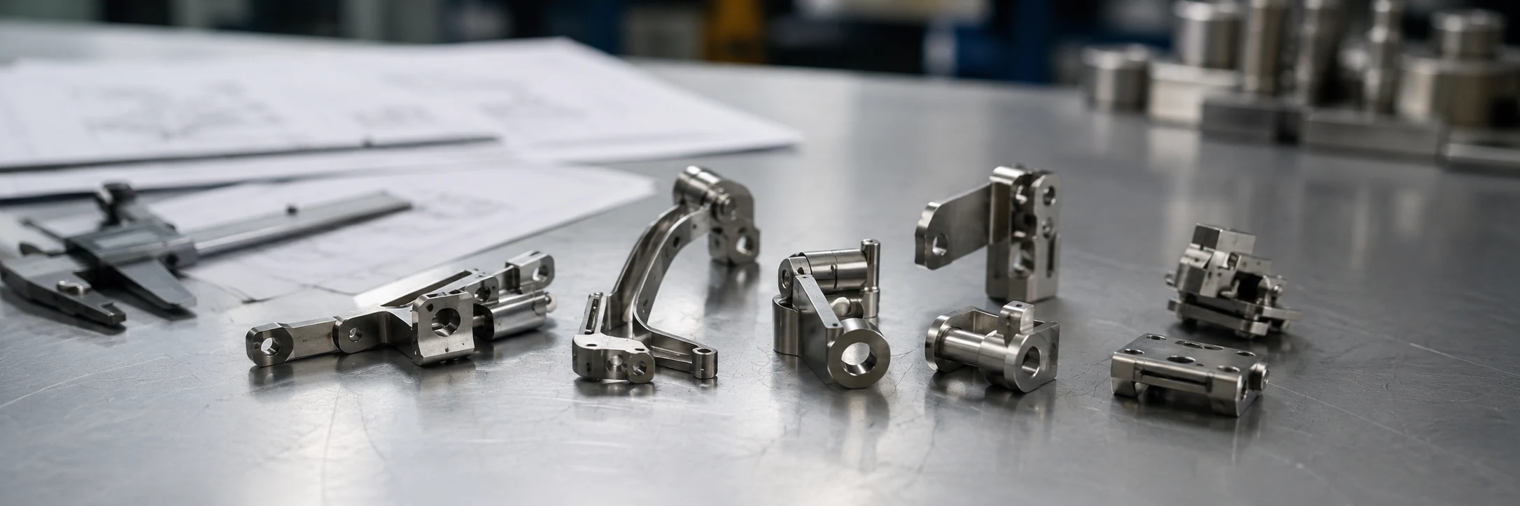
Core conclusion: MIM is most relevant when the part is small, complex, non-cutting, and suitable for drawing-based manufacturability review.
MIM Surgical Instrument Parts XTMIM Can Review
MIM is most useful for surgical instrument parts that behave like compact mechanical components rather than finished medical devices. These parts often have thin walls, small holes, locking teeth, hinge features, internal slots, curved profiles, or assembly interfaces that are expensive or inconsistent to produce by conventional machining alone.
Internal motion and retention components
Non-cutting mechanism parts may include small internal links, sliding elements, retention parts, actuation pieces, or motion-transfer components used inside a surgical instrument assembly. The engineering focus is whether the individual component has geometry, volume, material, and inspection requirements that fit the MIM process.
These parts should be reviewed as custom metal components, not as finished surgical devices. This keeps the manufacturing discussion focused on geometry, material direction, inspection, and assembly risk.
Handle inserts and internal metal frames
Handle inserts, reinforcement frames, internal supports, and small structural elements can be suitable for MIM when the part needs strength, compact geometry, and repeatable assembly location. These parts may work with polymer handles, mechanical locking systems, or multi-part instrument assemblies.
Before tooling, the project team should confirm whether the insert controls alignment, carries load, supports a hinge, or only provides internal reinforcement. This affects datum selection, inspection planning, and whether secondary operations are needed.
Locking, trigger, lever, and hinge-related components
Locking components, small triggers, levers, ratchet-like features, hinge links, and pivot-related parts may contain teeth, slots, holes, curved motion surfaces, and compact load-bearing areas. MIM can be attractive when the geometry is too complex for simple stamping but too repetitive for cost-efficient full CNC production.
The main review point is functional fit. A small tooth, pivot hole, or sliding surface may control the feel and motion of the assembly, so these features should be called out on the drawing before quotation.
Coupling, support, and compact structural parts
Coupling sleeves, small brackets, support frames, connection features, and compact structural parts can fit MIM when they include three-dimensional complexity. MIM becomes more relevant when small size is combined with difficult internal geometry, multiple features, repeatable volume, and material requirements that justify tooling.
If the part is only a flat plate, simple spacer, or very low-volume prototype, machining or stamping may still be more practical. MIM should be reviewed when the total manufacturing route, not only the unit shape, supports the project goal.

Core conclusion: The page should focus on small mechanical parts inside instrument assemblies rather than finished surgical tools.
| Part Type | MIM Review Fit | Reason |
|---|---|---|
| Handle inserts and internal support structures | Good fit | Small structural metal components with assembly features, ribs, bosses, holes, or compact support geometry. |
| Locking levers, trigger parts, and hinge links | Good fit | Compact mechanism geometry with holes, teeth, slots, pivot areas, or curved surfaces. |
| Coupling sleeves and small connection parts | Potential fit | Suitability depends on geometry, critical dimensions, material, and expected production volume. |
| Surgical blades, scalpel blades, and puncture tips | Not page focus | Cutting or puncture applications require separate qualification and risk review. |
| Implantable parts | Not page focus | Long-term body-contact applications involve separate material, regulatory, and qualification requirements. |
| Sterile finished instruments | Not page focus | Finished device supply, sterile packaging, and market authorization are outside a standard MIM component review. |
Which Surgical Instrument Parts Are Not a Good Fit for This Page
This page intentionally does not focus on all surgical instrument parts. Some parts involve direct tissue contact, cutting performance, puncture behavior, implant use, sterile packaging, or regulatory qualification requirements that go beyond a standard MIM component review.
Blades, cutting edges, and puncture tips
Surgical blades, scalpel blades, trocar tips, puncture tips, and sharp cutting-edge components are not the preferred focus of this page. These parts involve edge geometry, sharpness, tissue interaction, cleaning, validation, and regulatory risk that require a separate review path.
Implantable or long-term body-contact components
Implantable components and long-term body-contact parts should not be treated as ordinary surgical instrument parts. These applications may involve material biocompatibility, long-term performance, documentation, traceability, and regulatory review that must be defined before supplier selection.
Sterile finished instruments and regulatory-heavy products
XTMIM should not present this page as a sterile finished surgical instrument manufacturing service. The correct boundary is component manufacturing review, not sterile finished product supply.

Core conclusion: Blades, puncture tips, implants, sterile finished instruments, and direct tissue-contact cutting parts need a separate qualification path.
How this page fits within XTMIM medical parts content
This page supports the broader medical MIM parts category by focusing only on surgical instrument mechanism components that can be reviewed as custom metal parts. More specific medical component categories, such as endoscope parts, should remain separate topics.
Why MIM Can Fit Small Surgical Instrument Mechanism Components
MIM can be a strong option for small surgical instrument mechanism components when the part combines complex geometry, repeatable production, and material requirements that are difficult to satisfy economically with machining or stamping alone. The process is especially relevant when the part has integrated features that would otherwise require several operations or multiple assembled components.
Small complex geometry and near-net shape forming
MIM uses a feedstock of fine metal powder and binder, shaped by injection molding and then debound and sintered. This allows small metal components to be formed close to final geometry, with shrinkage and distortion managed through tooling compensation and process control.
For surgical instrument mechanism parts, this can be useful when a component has small holes, slots, curved surfaces, undercuts, ribs, bosses, or multi-directional features. The design should still be reviewed for DFM for MIM before tooling.
Integrated features that reduce assembly burden
One reason engineers consider MIM is the ability to integrate several functional features into one part. A compact lever may include a pivot hole, a stop surface, a small tooth profile, a curved contact surface, and a retaining feature.
If MIM can consolidate features without making the part too thick, too distorted, or too difficult to inspect, it may improve manufacturing consistency and reduce tolerance stack-up from multiple assembled pieces.
Repeatability for mechanism components
MIM becomes more attractive when the part will be produced repeatedly from a stable design. Tooling cost must be justified, so the process is usually more suitable for repeat production than for one-off prototypes.
The RFQ should identify expected annual volume, project stage, and whether the design is frozen or still changing. A changing design may need prototype machining or design validation before MIM tooling.
When CNC or stamping may still be better
CNC may be better for low volume, early prototypes, simple block-like shapes, very tight local machining requirements, or designs that may change frequently. Stamping may be better for flat sheet-metal parts, simple profiles, spring-like forms, or thin components with mostly two-dimensional geometry.
The right question is not only whether the part can be molded, but whether MIM remains practical after tooling, sintering, inspection, surface finishing, and any secondary operations are included.
Manufacturing review scope at XTMIM
XTMIM can review the manufacturing route for MIM-suitable components through MIM injection molding, debinding, sintering, and selected secondary operations. Injection molding and debinding are handled in-house, while sintering review may consider batch vacuum or continuous belt furnace routes depending on material and project requirements.
This manufacturing scope does not replace customer device qualification. It helps the project team decide whether the metal component is a reasonable MIM candidate before mold investment. Final material, cleaning, sterilization, and device qualification requirements must be defined by the customer’s project documentation.
Design Features to Check Before Tooling
Before tooling, MIM surgical instrument parts should be reviewed for geometry, shrinkage behavior, assembly interfaces, and functional risks. A drawing that looks compact and precise in CAD may still require design changes before it becomes a reliable MIM component.
Wall thickness and local mass balance
Wall thickness affects molding, debinding, sintering, and final dimensional stability. Sudden thick-to-thin transitions may create sink marks, distortion, differential shrinkage, or local weakness.
Before tooling, engineers should review wall thickness design, heavy sections, thin arms, ribs, and unsupported features together with the sintering support strategy.
Holes, slots, teeth, and locking features
Holes, slots, teeth, and locking profiles are common in surgical instrument mechanism parts. They are also common sources of review risk. Small holes may shift, sharp corners may concentrate stress, thin teeth may distort, and narrow slots may create molding or debinding challenges.
Features such as holes, slots and undercuts should be marked clearly when they control pivot motion, locking feel, or sliding movement.
Datum surfaces and critical assembly interfaces
A part can meet individual dimensions but still fail in assembly if datum strategy is unclear. Surgical instrument mechanisms often depend on the relationship between holes, faces, teeth, and contact surfaces.
The drawing should identify datum surfaces, mating part relationships, and MIM tolerance expectations before quotation. Without this information, the supplier may not know which features control final movement or fit.
Gate mark, parting line, and sintering support review
Gate location, parting line position, ejector marks, and sintering support strategy can affect both function and appearance. A gate mark on a hidden non-functional surface may be acceptable, while a mark on a sliding or contact surface may cause problems.
For compact mechanism parts, the project team should decide which surfaces are cosmetic, which surfaces are functional, and which surfaces can tolerate normal MIM process marks.

Core conclusion: A compact part may look suitable in CAD, but tooling risk depends on geometry, datum strategy, and sintering behavior.
DFM review checklist before tooling
- Confirm wall thickness and local mass balance.
- Mark critical holes, slots, teeth, and locking surfaces.
- Define datum surfaces and functional interfaces.
- Review gate mark and parting line sensitivity.
- Identify surfaces that may need secondary machining.
- Confirm whether surface finish affects movement or assembly.
- Provide mating part or assembly context where possible.
Material and Surface Finish Considerations
Material and surface finish choices for surgical instrument parts should be reviewed by function, environment, cleaning requirement, wear condition, and application risk. XTMIM should not describe a material as automatically suitable for all surgical uses. Instead, the project team should confirm material requirements from the drawing, device application, and customer qualification path.
| Review Area | Typical Question | Why It Matters |
|---|---|---|
| Stainless steel direction | Does the drawing call for 316L, 17-4PH, 420, or another customer-defined material? | Material selection affects corrosion review, strength direction, hardness planning, finishing route, and qualification logic. |
| Heat treatment or hardness | Does the part need load-bearing, wear, or locking surface performance? | Heat treatment may affect dimensional review, inspection planning, and final fit. |
| Surface finish | Are polishing, passivation, PVD, or other finish requirements defined? | Deep slots, small holes, masking, coating thickness, and functional surfaces may affect finishing feasibility. |
| Application risk | Is the part non-cutting, non-implantable, and reviewed as a component rather than a finished device? | The same material may require different review logic depending on contact, cleaning, and qualification requirements. |
Stainless steel material direction
Stainless steel materials are often reviewed for surgical instrument mechanism parts because the project may require corrosion review, strength direction, hardness planning, or defined surface finish requirements. Depending on the part function, materials such as 316L, 17-4PH, or 420 stainless steel may be considered. The final choice depends on the customer’s drawing, corrosion exposure, strength target, hardness requirement, post-treatment needs, and qualification path.
This page does not claim that one stainless steel grade is universally suitable for all medical or surgical applications. The correct material should be confirmed by the customer’s drawing, qualification path, and application risk.
Surface finish, passivation, PVD, and cleaning requirements
Surface finishing may include polishing, passivation, PVD coating, or other treatments depending on material, geometry, and application requirements. These options should be reviewed as project-specific requirements, not as universal guarantees for every surgical application.
PVD can be reviewed as an in-house capability only when part geometry, material, masking, coating thickness, and production requirements fit the confirmed process route. Deep slots, sharp internal transitions, and tight masking requirements should be reviewed before quotation.

Core conclusion: Material and finish are review items, not universal guarantees for every surgical application.
Inspection and Quality Review for MIM Surgical Instrument Parts
Inspection for MIM surgical instrument parts should focus on the features that affect assembly, function, movement, and supplier approval. The goal is not to inspect every dimension equally, but to understand which features are critical to the part’s role in the instrument assembly.
Critical dimensions and functional interfaces
Critical dimensions may include pivot holes, tooth profiles, locking surfaces, locating bosses, slot widths, and datum-related surfaces. These features should be identified clearly on the drawing.
If all dimensions are treated as equally important, quotation and inspection planning become less efficient. Critical-to-function features should be separated from general dimensions before supplier review.
Visual surface and edge condition review
For MIM components, surface review may include gate marks, parting line visibility, polishing feasibility, burr condition after secondary operations, and edge condition on non-cutting features.
Edge condition should be reviewed for handling, assembly, and movement. This page should not be interpreted as approval for cutting edges, puncture edges, or direct tissue-contact cutting performance.
Fit, movement, and assembly risk
Some surgical instrument mechanism parts must move smoothly inside an assembly. A small deviation in hole position, tooth shape, or contact surface may create poor fit or inconsistent movement.
Fit review is more reliable when the customer provides mating part information, functional notes, and any existing inspection method. Without assembly context, the supplier may not know which dimensions control final performance.
Documentation needed for supplier evaluation
Useful documents include 2D drawings, 3D models, material requirements, surface finish requirements, critical dimensions, annual volume, project stage, and notes on the assembly environment.
These documents help separate manufacturing feasibility from final device qualification. XTMIM can review the metal component route, while the customer defines application-specific approval requirements.
Manufacturing review is not final device qualification
XTMIM can support MIM manufacturability review, DFM discussion, tooling-risk evaluation, and process-route review for small metal components. The customer remains responsible for final device qualification, regulatory pathway, sterilization validation, cleaning validation, labeling, and application-specific approval requirements. This page does not claim sterile finished instrument supply, implant suitability, universal medical-grade certification, or full PPAP support for all projects.
RFQ Information Needed for Surgical Instrument Part Review
A good RFQ package helps determine whether a surgical instrument component is suitable for MIM, what risks need review, and whether the part should remain in MIM or use another process. The more clearly the functional and dimensional requirements are defined, the more accurate the manufacturing review can be.
2D drawing and 3D model
A 3D model helps understand geometry, but a 2D drawing is still important for tolerances, critical features, surface notes, and material requirements. The drawing should identify datum surfaces, critical dimensions, and any surfaces that require secondary operations.
Material, finish, and functional requirements
The RFQ should include target material, heat treatment or hardness requirements, surface finish expectations, coating or passivation needs, and functional requirements such as movement, wear resistance, corrosion exposure, or assembly fit.
Annual volume and project stage
MIM tooling should be justified by production volume and design stability. The RFQ should state whether the project is at prototype, validation, pilot, or mass production stage.
Critical dimensions and assembly position
Critical dimensions should be marked clearly. The supplier should know which dimensions affect motion, locking, fitting, and assembly. The assembly position also matters because visible surfaces, functional surfaces, and hidden surfaces may need different tooling and finishing decisions.

Core conclusion: Drawings, 3D models, material targets, critical dimensions, volume, and assembly notes improve the accuracy of MIM review.
RFQ input checklist
- 2D drawing with tolerances.
- 3D CAD model.
- Target material and any customer specification.
- Surface finish or coating requirement.
- Critical dimensions and functional surfaces.
- Expected annual volume.
- Project stage: prototype, validation, pilot, or production.
- Assembly position and mating part context.
- Cleaning, corrosion, wear, or movement requirements if applicable.
Composite Engineering Scenario for RFQ Review
This representative scenario is used for engineering training only. It does not describe a specific customer, order, validation result, or production case.
A small locking lever inside a reusable instrument assembly may look suitable for MIM because it has a compact body, a pivot hole, a curved contact surface, and a small locking tooth. During review, the team may still find that the tooth profile needs radius adjustment, the pivot hole requires a clearer datum, and the lever arm needs better wall balance to reduce sintering risk.
This example shows why a MIM RFQ should include both geometry and function. The same part may be acceptable for MIM after DFM adjustment, or it may require CNC finishing on one or two critical surfaces.
FAQ About MIM Surgical Instrument Parts
These answers help engineering and sourcing teams decide whether a drawing is ready for MIM manufacturability review.
Can MIM be used for surgical instrument parts?
Yes, MIM can be reviewed for small, complex, non-cutting metal parts used in surgical instrument assemblies. The best candidates are mechanism parts, handle inserts, locking components, levers, hinge-related parts, coupling parts, and small structural components. Blades, puncture tips, implants, sterile finished instruments, and direct tissue-contact cutting parts require separate qualification review and are not the focus of this page.
Which surgical instrument parts are not recommended for this page?
This page does not focus on surgical blades, scalpel blades, trocar tips, implantable components, sterile finished instruments, or direct tissue-contact cutting tools. These parts involve application risk, validation, and regulatory requirements that go beyond a standard MIM component review.
What materials are commonly reviewed for these parts?
Stainless steel materials such as 316L, 17-4PH, and 420 may be reviewed depending on corrosion exposure, strength, hardness, wear condition, and customer specification. The final material should be confirmed by the drawing, application risk, surface requirements, and qualification path.
Can XTMIM quote without a complete drawing?
XTMIM can provide a preliminary direction review from a 3D model or basic information, but a formal quotation normally requires a 2D drawing, 3D model, material target, surface finish requirements, critical dimensions, annual volume, and project stage.
When is CNC better than MIM for surgical instrument components?
CNC may be better for low-volume prototypes, simple geometries, frequently changing designs, or parts with very tight local features that require machining regardless of the base process. MIM is more suitable when the design is stable, the geometry is complex, and repeat production can justify tooling.
Can surface finishing be included after MIM?
Surface finishing can be reviewed depending on the material, geometry, surface function, and project requirements. Options may include polishing, passivation, PVD coating, or other treatments, but feasibility depends on part shape, masking needs, coating requirements, and final use conditions.
Does XTMIM provide final medical device qualification for these parts?
No. XTMIM can review MIM manufacturability, DFM risk, material direction, tooling considerations, secondary operation needs, and inspection focus for custom metal components. Final device qualification, regulatory approval, sterile packaging, implant suitability, and application-specific validation remain the customer’s responsibility.
Review Your Surgical Instrument Mechanism Part Before MIM Tooling
Send XTMIM your 2D drawing, 3D model, material target, critical dimensions, surface finish requirements, expected annual volume, and assembly notes. Our engineering team can review whether the part is suitable for MIM, which features may need DFM adjustment, and whether secondary operations should be considered before tooling.