
Review when metal injection molding is suitable for selected small metal components in commercial and industrial drone platforms, including compact hinges, brackets, shafts, pins, locking features, sensor supports, and wear-contact parts.
Quick answer: Metal injection molding can be a practical production route for selected drone components when the part is small, geometrically complex, functionally metal, stable in design, and required in repeat volume. It is most relevant when several bosses, ribs, slots, pivot details, locating surfaces, or curved profiles can be integrated into one near-net-shape component. MIM is usually a weak fit for large structures, simple low-volume brackets, frequently changing prototypes, or parts that can meet the requirement through plastic molding, sheet metal, or straightforward machining.
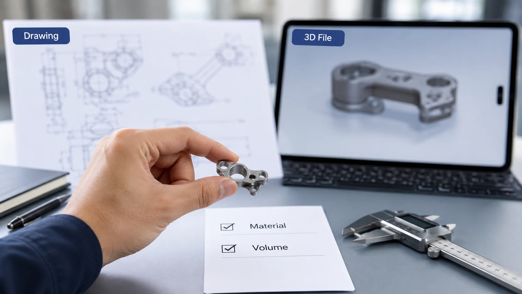
Image disclosure: Representative illustration for engineering discussion; it does not depict a verified customer project or a specific XTMIM production program.
When a Drone Component Is a Strong MIM Candidate
The strongest candidates combine compact geometry, a clear metal function, stable design requirements, and enough repeat production to justify tooling.
Commercial drone assemblies often place several functions inside a limited package. A small component may need to locate a sensor, support a camera module, carry a pivot, lock a battery cover, maintain alignment, or resist repeated contact. MIM becomes relevant when these functions create geometry that is inefficient to machine as a single part and when the design team can clearly identify the load path, mating surfaces, datums, wear areas, and inspection requirements.
The process does not make every drone component lighter or cheaper. Its value appears when feature integration can reduce repeated machining while preserving the metal function required by the assembly. Before tooling review, the team should confirm whether the part is still changing, whether the annual demand is realistic, and whether critical dimensions are tied to assembly performance rather than applied as unnecessarily tight general tolerances. For broader application routing, this page remains focused on commercial and industrial drone component suitability rather than general MIM industry coverage.
Compact integrated geometry
Bosses, ribs, slots, curved profiles, pivot details, and locating features may be combined in one small metal component.
Functional metal requirement
Load, wear, corrosion, positioning, heat, surface condition, or assembly repeatability must justify a metal route.
Stable repeat production
The design should be mature enough for tooling, shrinkage compensation, validation, and repeat inspection.
| Stronger MIM Candidate | Weak MIM Candidate | Recommended Review |
|---|---|---|
| Small component with integrated bosses, ribs, slots, pivot details, or curved geometry. | Simple plate, spacer, shell, or large structural frame. | Confirm whether feature integration creates a real manufacturing advantage. |
| Stable design with repeat production demand. | Prototype geometry still changes after each assembly trial. | Continue prototype validation before committing to MIM tooling. |
| Metal is required for load, wear, corrosion, positioning, or assembly fit. | Plastic, sheet metal, or simple machining already meets the functional requirement. | Compare the simplest viable process before selecting MIM. |
| Critical dimensions and functional datums are clearly defined. | The drawing applies tight general tolerances without a functional reason. | Separate assembly-critical dimensions from standard process dimensions. |
| Several machined features may be consolidated into one near-net-shape part. | Only one local precision feature is needed on an otherwise simple part. | Compare tooling cost with CNC and any required secondary operations. |
Tooling boundary
MIM is not a rapid prototype process. Tooling, feedstock selection, shrinkage compensation, debinding, sintering, validation, and inspection all depend on a reasonably stable design. A project should not move to final tooling while mounting positions, load paths, wall transitions, or mating surfaces are still changing.
Drone Component Functions Commonly Reviewed for MIM
Part names alone do not determine process suitability. The engineering function and geometry are more important.
Hinges, pivots, and locking features
Folding arms, covers, access mechanisms, and compact moving assemblies may require controlled contact surfaces, locating details, and wear-resistant metal features.
Compact brackets and sensor supports
Camera, antenna, sensor, or frame-mounted supports may combine bosses, ribs, holes, and alignment surfaces within limited space.
Shafts, pins, and linkage elements
Pivot and linkage parts require early review of fit, straightness, surface condition, wear, and possible post-sintering operations.
Small drive or adjustment parts
Selected gear-related or adjustment components may be reviewed when the geometry is compact, repeatable, and compatible with the required material and inspection route.
These groups are application examples rather than automatic MIM approvals. Large frames, simple sheet-metal brackets, frequently changing prototypes, and very low-volume parts usually require another manufacturing route. For part-family examples and drawing-level considerations, review the drone MIM parts page.

Image disclosure: Representative illustration only; the components shown should not be interpreted as verified customer parts or XTMIM production records.
MIM, CNC, and Additive Routes Serve Different Project Stages
The correct route depends on design maturity, geometry, volume, functional surfaces, and the cost of tooling or secondary operations.
| Process Route | Strong Fit | Boundary for Drone Components |
|---|---|---|
| CNC machining | Prototypes, low volume, simple geometry, and tight local features. | Cost can increase when many small features must be machined repeatedly. |
| Additive routes | Geometry exploration, design validation, and low-volume prototype evaluation. | Useful before tooling, but production economics and material behavior differ from MIM. |
| MIM | Small complex metal components with stable geometry and repeat demand. | Weak for large parts, frequently changing designs, and projects that cannot justify tooling. |
CNC prototypes or additive validation parts can help confirm assembly function before the geometry is frozen. MIM should be reviewed later, when the team can compare tooling investment against repeated machining, expected annual volume, secondary operations, and inspection requirements. For a focused production-route comparison, review MIM vs CNC.

Image disclosure: Representative illustration for process-selection discussion; it is not a documented comparison from a specific customer project.
Material and Surface Requirements Must Follow the Part Function
Material selection should begin with what the component must do, not with a generic drone-part label.
Define the functional requirement
Confirm whether the component locates, pivots, supports, locks, slides, carries load, resists corrosion, or provides a magnetic function.
Identify the final surface condition
Wear areas, mating surfaces, cosmetic faces, masking zones, coating thickness, friction, and post-sintering machining should be defined before quotation.
Stainless steels may be reviewed for corrosion resistance and stable appearance; low-alloy steels may be considered for strength-oriented parts; wear-focused routes may be relevant to repeated contact; and soft magnetic materials are appropriate only when the component has a clear magnetic function. These are material directions, not automatic selections. Final material, heat treatment, surface finishing, and inspection requirements must be confirmed against the drawing and application environment.

Image disclosure: Representative illustration only; finishes and parts shown do not confirm a specific production material, coating, or customer application.
Engineering Review Before Drone MIM Tooling
DFM, inspection planning, and RFQ preparation should be handled as one connected review before tooling decisions.
A practical review connects the component function to geometry, material, shrinkage behavior, secondary operations, inspection method, and production demand. The goal is not to tighten every dimension. It is to identify the surfaces and features that control assembly, movement, alignment, wear, or load, while allowing noncritical areas to follow a realistic MIM process capability.
| Review Item | What the Project Team Should Confirm | Why It Matters |
|---|---|---|
| Design maturity | Mounting positions, load paths, wall transitions, mating surfaces, and overall geometry are reasonably stable. | Late changes can require tooling correction and renewed shrinkage validation. |
| Functional datums and fits | Critical holes, shafts, pivot areas, alignment faces, flatness requirements, and mating features are identified. | These features define assembly performance and inspection strategy. |
| Moldable geometry | Wall thickness, transitions, ribs, bosses, holes, slots, undercuts, and thread requirements are reviewed. | Some features may be molded, while others may need sizing or machining. |
| Material and final surface | Strength, wear, corrosion, appearance, coating, masking, friction, and heat-treatment requirements are stated. | Material and finishing choices affect processing, dimensions, and acceptance. |
| Inspection and acceptance | Datum strategy, critical dimensions, fit requirements, surface expectations, and measurement methods are defined. | Visual acceptance alone cannot confirm functional performance. |
| RFQ and production inputs | 2D drawing, 3D CAD, target material, annual volume, current process, launch stage, and assembly function are provided. | These inputs support a realistic technical and commercial review. |
Representative engineering scenario
Consider a compact hinge-and-bracket assembly for a folding drone module. CNC prototypes may be suitable during assembly testing, but the production candidate includes a pivot-contact area, locating features, a curved support profile, and alignment-sensitive faces. MIM may be worth reviewing only after the geometry is stable, functional surfaces are identified, and repeat volume can justify tooling. This is a representative scenario, not a customer case or production claim.
A drawing-level review should determine what can be molded, what may require sizing or machining, and how the part will be inspected after sintering and any secondary operation. Review the MIM design review before tooling for DFM readiness, and use the MIM RFQ preparation guide to organize project inputs.

Image disclosure: Representative illustration for RFQ and DFM guidance; it does not document a verified customer drawing, sample, or production project.
FAQ: MIM for Commercial Drone Components
These questions address the main process-fit and tooling-review decisions.
Is MIM suitable for all drone components?
No. MIM is mainly considered for selected small metal components with complex geometry, stable design requirements, repeat production demand, and a clear functional reason to use metal. Large structures, simple low-volume parts, plastic covers, and frequently changing prototypes usually fit other manufacturing routes better.
When can MIM be a better production route than CNC?
MIM becomes more relevant when several small machined features can be integrated into one repeatable near-net-shape component and production volume can justify tooling. CNC remains useful for prototypes, low volume, simple geometry, tight local machining, and secondary operations after sintering.
What information is needed to review a drone component for MIM?
Provide the 2D drawing, 3D CAD file, material target or current material, annual volume, launch stage, current manufacturing route, critical dimensions, surface requirements, and assembly function. These inputs help determine geometry, tooling, secondary-operation, inspection, and commercial risks.
What is the main tooling risk for a drone MIM component?
The main risk is committing to tooling before the design and functional surfaces are stable. Changes to mounting positions, load paths, wall transitions, datums, fits, or mating surfaces can require tooling correction and renewed process validation.
Technical Reference
This non-competitor industry reference supports the general explanation of MIM feedstock forming, debinding, and sintering. Project-specific material, tolerance, inspection, and finishing requirements still require drawing-level confirmation.
- Metal Injection Molding Association, What is MIM?
Review a Drone Component for MIM Suitability
Send the drawing, 3D file, material target, annual volume, critical dimensions, surface requirements, and assembly function. XTMIM can review whether MIM is a reasonable route before tooling decisions.