
MIM vs Die Casting: How to Choose the Right Metal Part Manufacturing Process
Choose between MIM and high-pressure die casting by starting with the required material and part type. MIM is usually evaluated for small, complex, steel-based or other MIM-suitable precision parts. Die casting is usually evaluated for aluminum, zinc, or magnesium housings, covers, brackets, heat sinks, and enclosures. The practical decision depends on material, size, geometry, critical tolerances, annual volume, quality risks, and secondary operations—not on which process sounds cheaper. This guide provides the core selection logic and directs deeper size, drawing, and supplier-quote questions to dedicated engineering reviews.
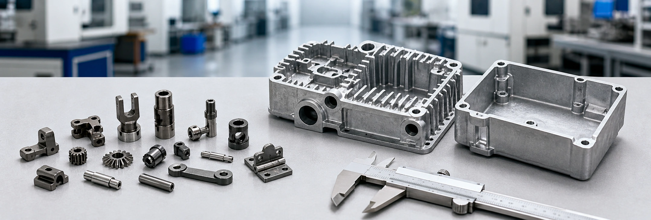
This visual explains process-selection logic. It is not presented as a customer project, production record, or photograph of a specific XTMIM-manufactured part.
MIM and die casting solve different manufacturing problems. A small stainless steel component with undercuts, fine holes, or feature-consolidation potential may justify a metal injection molding review. A medium-sized aluminum housing normally points toward die casting. Make this distinction before tooling so the project does not inherit the wrong material route, machining scope, dimensional controls, or quality-risk assumptions.
MIM vs Die Casting: Quick Process Decision
MIM uses metal-powder feedstock, injection molding, debinding, and sintering. High-pressure die casting injects molten aluminum, zinc, or magnesium alloy into a steel die. MIM is usually the stronger starting point for small, complex, steel-based parts that may consolidate machining or assembly. Die casting is usually the stronger starting point for medium-to-large non-ferrous housings, covers, brackets, heat sinks, and enclosures. If the design is still changing or the requirement is limited to a few prototypes, CNC or another prototype route may be more practical before production tooling.
Process Decision Snapshot
| Part or Project Direction | Start With | Primary Engineering Reason |
|---|---|---|
| Small complex stainless steel, alloy steel, tool steel, or other MIM-suitable part | MIM review | The material route and feature density may justify powder injection molding, sintering, and limited finishing of critical features. |
| Aluminum, zinc, or magnesium housing, cover, bracket, heat sink, or enclosure | Die casting review | The non-ferrous alloy route, projected area, and component scale usually fit high-pressure casting better. |
| Small part replacing multiple CNC operations or assembled features | MIM review | Near-net-shape feature consolidation may reduce machining and assembly at repeat volume. |
| Porosity-sensitive non-ferrous part with sealing or deep machining requirements | Die casting review with added quality controls | Metal flow, venting, porosity, machining exposure, and leak-test requirements must be defined before tooling. |
| Very low-volume prototype or frequently changing design | Prototype route first | Production tooling for either process may be premature until geometry, material, and functional requirements are stable. |
How MIM and Die Casting Work Differently
MIM Uses Powder Feedstock, Debinding, and Sintering
Metal injection molding starts with fine metal powder mixed with a binder system to create feedstock. The feedstock is injection molded into a green part, then debound to remove binder, and finally sintered to densify the part and develop the required metal properties. You can review the complete MIM process if you need a deeper process-level explanation.
The simplified process route is: fine metal powder + binder → feedstock → injection molding → debinding → sintering → secondary operations if needed.
This matters because MIM is not metal melted into a mold. The final part size is strongly affected by sintering shrinkage, tooling compensation, debinding stability, sintering support, and inspection of critical dimensions.
MIM is strongest when the part is small, geometrically complex, and difficult or expensive to machine from bar stock. Features such as small holes, slots, thin walls, undercuts, complex profiles, and integrated functional details can often be molded into the green part before sintering. However, this advantage only works when the part design, material, tolerance, and production volume are suitable for MIM.
Die Casting Injects Molten Metal into a Steel Die
High-pressure die casting injects molten metal, typically aluminum, zinc, or magnesium alloy, into a steel die under pressure. The metal fills the cavity, cools, solidifies, and is ejected. After casting, the part usually requires trimming, deburring, machining, surface finishing, or inspection depending on the application.
The simplified process route is: molten aluminum / zinc / magnesium alloy → high-pressure injection → cooling → ejection → trimming → machining or finishing if needed.
Die casting is strong when the part is a medium-to-large non-ferrous component, especially a housing, cover, bracket, enclosure, or heat sink. It can support fast production cycles and high-volume manufacturing when the alloy, die design, machine tonnage, wall thickness, and finishing requirements are properly matched.
The main risks are different from MIM. Die casting projects need to manage metal flow, air entrapment, porosity, flash, parting lines, ejector marks, trimming variation, machining allowance, and die wear.

This visual explains engineering comparison logic. It is not presented as a customer project, production record, or photograph of a specific XTMIM-manufactured part.
Material Selection Is Usually the First Decision Point
Material is often the first reason why one process becomes more realistic than the other. Before comparing cost or tolerance, engineers should ask: What metal does the part actually need?
When MIM Materials Make More Sense
MIM is commonly considered for small precision parts made from stainless steel, low alloy steel, tool steel, titanium alloy, soft magnetic alloy, wear-resistant alloys, and other high-density small metal part materials suitable for MIM. If your project is still in the material review stage, the MIM materials page can help organize the material direction before detailed DFM review.
If the part requires stainless steel, high strength, corrosion resistance, wear resistance, or complex steel-based geometry, MIM is usually more relevant than die casting.
A common example is a small stainless steel mechanism part with multiple holes, slots, locking features, and tight assembly requirements. If made by CNC, the machining time may be high. If redesigned for MIM, many features may be formed in the mold, with secondary machining limited to critical surfaces if required.
When Die Casting Materials Make More Sense
Die casting is usually more relevant for aluminum alloys, zinc alloys, and magnesium alloys. Typical die cast parts include aluminum housings, zinc covers, magnesium lightweight structures, heat sinks, brackets, enclosures, consumer hardware shells, electronic housings, and automotive non-ferrous structural parts.
If the target part is an aluminum housing, zinc cover, magnesium enclosure, or heat sink, die casting is usually a better starting point than MIM. In these cases, the material direction and part size already point toward a non-ferrous casting route.
Common Material Mistake: Comparing Stainless Steel MIM with Aluminum Die Casting
A common mistake is to compare MIM and die casting as if they were two interchangeable methods for the same metal. In many real projects, they are not.
| MIM Direction | Die Casting Direction |
|---|---|
| Stainless steel | Aluminum |
| Low alloy steel | Zinc |
| Titanium alloy | Magnesium |
| Tool steel | Non-ferrous casting alloys |
| Soft magnetic alloy | Lightweight cast alloys |
If a customer asks whether MIM or die casting is cheaper, the first answer should be: confirm the material first. If the project requires stainless steel, aluminum die casting is not a direct comparison. If the project requires an aluminum enclosure, MIM is usually not the first process to evaluate.

This visual explains engineering comparison logic. It is not presented as a customer project, production record, or photograph of a specific XTMIM-manufactured part.
Not Sure Whether the Material Route Fits MIM or Die Casting?
Send the material requirement, 2D drawing, 3D CAD file, and estimated annual volume for a drawing-based process suitability review before tooling. The review should confirm whether the part is closer to MIM, die casting, CNC machining, or another manufacturing route.
Submit a Drawing for Review Contact Our Engineering TeamPart Size and Geometry: Use Them as Review Triggers
MIM generally becomes more relevant as a part becomes smaller, more feature-dense, and more expensive to machine or assemble. Die casting generally becomes more relevant as a non-ferrous component becomes larger in projected area and takes the form of a housing, cover, bracket, enclosure, or heat sink. These are engineering directions rather than universal size or weight limits.
Do not choose the process from outer dimensions alone. Review material route, local wall sections, flow length, projected area, critical features, tooling layout, annual volume, and the secondary operations that remain after molding or casting. For the deeper size, weight, wall-thickness, and projected-area decision path, use the part size and weight triggers for MIM vs die casting.
| Geometry Signal | MIM Direction | Die Casting Direction |
|---|---|---|
| Small steel-based part with fine holes, slots, undercuts, or integrated functions | Strong review candidate | Usually limited by material route or feature scale |
| Medium-to-large aluminum, zinc, or magnesium housing | Usually not the first route | Strong review candidate |
| Part consolidation replacing several machined or assembled features | Potentially valuable | Possible, but depends on alloy, die access, and casting geometry |
| Broad projected area, heat-sink fins, enclosure ribs, and bosses | Often uneconomic or unsuitable | Usually more relevant |
| Simple geometry or very low annual volume | Review CNC, stamping, PM, or another route first | Review prototype or alternative production routes first |
Tolerance and Drawing Review: Control Different Process Risks
Neither process has universally “better tolerance.” MIM dimensional control depends on tooling compensation, molding consistency, debinding stability, sintering shrinkage, support strategy, distortion control, and inspection. Die casting dimensional control depends on filling, cooling, die condition, parting lines, flash, ejection, trimming, porosity exposure, and machining allowance.
Before tooling, identify the critical bores, datums, sealing faces, threads, thin walls, long slots, and unsupported features on the drawing. Decide which features can remain as-molded or as-cast, which require secondary machining, and how they will be inspected. The detailed feature-by-feature review belongs in the drawing review triggers before choosing MIM or die casting.
| Critical Feature | MIM Review Focus | Die Casting Review Focus |
|---|---|---|
| Bore, datum, or mating dimension | Sintering drift, sizing or machining need, and inspection method | Machining allowance, position after casting, and porosity exposure |
| Thin wall or local thick-to-thin transition | Molding fill, debinding path, shrinkage balance, and distortion | Metal flow, cooling balance, local shrinkage, and flash |
| Thread or precision hole | Molded, tapped, or machined after sintering | Cast boss design, tapping, insert strategy, or machining |
| Sealing or pressure-related surface | Density, flatness, surface condition, and finishing need | Porosity, leakage risk, machining exposure, and test requirement |
| Long slot, thin arm, rib, or unsupported feature | Handling, support, and sintering distortion | Flow, ejection, parting-line position, and trimming |
Strength, Density, and Porosity: Different Quality Risks
MIM Parts Depend on Sintered Density and Process Control
MIM quality depends on feedstock consistency, molding stability, debinding control, sintering density, shrinkage behavior, and final inspection. A well-controlled MIM process can produce high-density metal parts, but the result depends on the material system, part design, and process control.
Important MIM quality considerations include feedstock uniformity, debinding control, sintering density, sintering distortion, hardness and strength requirements, heat treatment if required, and inspection of critical features.
MIM quality risks are not mainly die casting porosity risks. They are powder, binder removal, sintering, density, distortion, and dimensional control risks. If a project requires high strength, corrosion resistance, wear resistance, magnetic behavior, or heat treatment response, these requirements should be reviewed against the selected MIM material and process route.
Die Casting Parts Often Need Porosity and Flow Defect Control
Die casting quality often depends on melt handling, die temperature, filling behavior, venting, pressure, solidification, and trimming or machining. Porosity is one of the most important concerns, especially when the part requires sealing, pressure resistance, deep machining, plating, or high cosmetic quality.
Important die casting quality considerations include gas porosity, shrinkage porosity, cold shut, flow marks, blistering, leakage risk, and machining exposing pores.
If a die cast part will be machined after casting, porosity risk becomes more important because machining may expose internal voids. If the part needs pressure tightness, coating, plating, or high-strength performance, the die casting supplier must review these requirements before tooling.
| Quality Issue | More Related Process | Root Cause | Project Impact |
|---|---|---|---|
| Sintering distortion | MIM | Uneven shrinkage or poor support | Critical dimension variation |
| Debinding crack | MIM | Binder removal instability | Scrap or hidden weakness |
| Density variation | MIM | Sintering or feedstock instability | Strength and performance risk |
| Gas porosity | Die casting | Trapped gas during filling | Leakage or machining defects |
| Shrinkage porosity | Die casting | Solidification shrinkage | Weakness or pressure failure |
| Flash | Die casting | Die parting, pressure, or die wear | Trimming and dimensional risk |
| Gate mark | Both | Gate design and removal | Cosmetic or functional concern |

This visual explains engineering comparison logic. It is not presented as a customer project, production record, or photograph of a specific XTMIM-manufactured part.
Cost Comparison Requires the Same RFQ Scope
MIM and die casting quotes are not comparable until both suppliers are working from the same drawing revision, material requirement, annual volume, tooling scope, secondary operations, inspection level, surface finish, packaging, and commercial assumptions. Unit price alone can hide different machining allowances, finishing steps, validation work, or quality controls.
A small, complex steel part may favor MIM when feature consolidation reduces machining and assembly. A larger aluminum or zinc component may favor die casting when the alloy, scale, and cycle economics fit. For a broader view of MIM-side economics, review metal injection molding cost. For supplier-by-supplier comparison, use the quote comparison checklist for MIM and die casting suppliers before selecting a price.
Production Volume and Tooling: Both Need Enough Volume to Justify the Mold
MIM Volume Logic
MIM usually makes sense when the project has enough production volume to justify tooling, process development, debinding, sintering, and inspection planning. It is not normally the first choice for a few prototype pieces unless the project is moving toward production.
In early development, CNC prototypes may be useful for checking assembly, function, and geometry. But a CNC prototype does not prove that the part is ready for MIM production. Before MIM tooling, the design should be reviewed for wall thickness, sink or distortion risk, gate location, debinding stability, sintering support, and critical dimensions.
Die Casting Volume Logic
Die casting also requires tooling investment. It is generally strongest when the part volume is high enough to benefit from fast production cycles and die life. For aluminum or zinc housings, covers, brackets, and enclosures, the unit cost can become attractive when the part design and production quantity fit the die casting route.
However, high volume alone is not enough. The design must also allow proper metal flow, venting, ejection, trimming, machining, and finishing.
Prototype-to-Production Risk
A prototype made by CNC, 3D printing, or soft tooling does not automatically validate MIM or die casting production. The production process must be selected based on the final material, functional surfaces, critical tolerances, application environment, annual volume, and quality requirements.
From a project management perspective, the best time to compare MIM and die casting is before tooling. Once tooling is built, changing the material route or process route can become expensive.
Surface Finish and Secondary Operations
MIM Secondary Operations
MIM can reduce machining, but it does not mean no secondary operation is ever needed. Depending on the part, application, and tolerance requirements, secondary operations may include sizing, CNC machining of critical features, heat treatment, polishing, passivation, plating or coating if applicable, and final inspection.
For stainless steel MIM parts, passivation or polishing may be needed depending on corrosion or surface requirements. For high-strength parts, heat treatment may be required. For critical holes, bores, threads, or mating surfaces, machining may still be necessary. Learn more about MIM secondary operations if the project requires post-sintering processing.
Die Casting Secondary Operations
Die casting can produce near-net-shape parts quickly, but post-processing is often part of the total manufacturing route. Secondary operations may include trimming, deburring, shot blasting, machining, tapping, powder coating, anodizing for aluminum die casting, plating for zinc die casting, and leak testing if required.
A smooth cast surface does not automatically mean the part is finished. Flash, parting lines, ejector marks, machining allowance, coating requirements, and leak testing can all affect total cost and production planning.
When You Should Not Choose MIM or Die Casting
When MIM May Not Be the Right Choice
- The part is too large.
- Aluminum is the required material.
- The geometry is simple and CNC or stamping is cheaper.
- Annual volume cannot support tooling.
- Tolerance requires extensive machining anyway.
- Part weight is too high for MIM economics.
- The project is only a very low-volume prototype.
MIM should not be selected only because the part is metal. It should be selected because the geometry, material, tolerance, and volume create a real advantage for powder injection molding and sintering.
When Die Casting May Not Be the Right Choice
- Stainless steel is required.
- Titanium or tool steel is required.
- The part is very small with fine internal features.
- Porosity cannot be accepted.
- Machining may expose internal pores.
- High density or high strength is critical.
- The geometry is too small or too intricate for practical die casting.
Die casting should not be treated as a universal replacement for all metal parts. It is a strong process for suitable non-ferrous cast components, but material and porosity limitations must be reviewed carefully.
Common Wrong Assumptions When Comparing MIM and Die Casting
- Die casting is always cheaper.
- MIM is only for expensive parts.
- Aluminum parts can always be made by MIM.
- Stainless steel parts can be treated like aluminum die castings.
- A good as-molded surface means no secondary operation is needed.
- Tight tolerance never requires machining.
- Small metal parts are always better for CNC.
- Casting and die casting are the same thing.
The correct process choice must be based on material, size, geometry, tolerance, annual volume, post-processing, and application risk. If any of these details are unclear, the project should be reviewed before tooling.
MIM vs Die Casting Selection Checklist
Choose MIM if:
- Your part is small and complex.
- Stainless steel, titanium, tool steel, or alloy steel is required.
- Fine details, small holes, grooves, or undercuts are important.
- CNC machining cost is too high.
- Part consolidation can reduce assembly.
- High-density metal properties are required.
- Annual volume can support tooling and process validation.
- Secondary machining is limited to critical features only.
Choose Die Casting if:
- Your part is aluminum, zinc, or magnesium.
- The part is a housing, cover, bracket, enclosure, or heat sink.
- Production speed is important.
- Part size is medium to large.
- Thin-wall non-ferrous casting is suitable.
- Trimming, machining, and surface finishing are acceptable.
- Porosity risk can be managed for the application.
- High-volume production can justify die tooling.

This visual explains engineering comparison logic. It is not presented as a customer project, production record, or photograph of a specific XTMIM-manufactured part.
Representative Engineering Scenarios
The following representative scenarios illustrate common process-selection conditions. They are not customer case studies, production records, or descriptions of specific orders.
Scenario A: Small Stainless Steel Locking Component
| Review Point | Engineering Interpretation |
|---|---|
| Typical problem | Several slots, holes, and locking features make CNC machining time and unit cost difficult to control at repeat volume. |
| Why it happens | The design combines small size, stainless steel, and multiple functional features that are inefficient to machine individually. |
| Underlying process-selection issue | The project is being treated only as a machining task rather than a possible small-part feature-consolidation opportunity. |
| Recommended review direction | Evaluate MIM feasibility, including gate location, wall balance, debinding stability, sintering distortion, critical dimensions, and post-sintering machining. |
| Prevention before tooling | Confirm material, annual volume, critical tolerances, functional surfaces, and which features must remain machined after sintering. |
MIM is worth evaluating because the part is small, complex, steel-based, and may benefit from feature consolidation. Approval still depends on the drawing. An extremely tight bore, datum, or functional surface may require machining or a different manufacturing route.
Scenario B: Aluminum Electronic Housing
| Review Point | Engineering Interpretation |
|---|---|
| Typical problem | The project is compared with MIM only because both processes use tooling, even though the part is a medium-sized aluminum housing with ribs, bosses, and enclosure functions. |
| Why it happens | The comparison starts from process names instead of the required material route, projected area, and component scale. |
| Underlying process-selection issue | The part belongs to a non-ferrous housing application where high-pressure die casting is usually more relevant. |
| Recommended review direction | Review draft, wall sections, metal flow, parting line, ejection, porosity, machining allowance, surface finishing, and leakage requirements. |
| Prevention before tooling | Confirm whether the project is a small steel-based precision component or a larger aluminum, zinc, or magnesium casting before comparing price. |
These scenarios show why MIM and die casting should be compared through material, geometry, tolerance, volume, and quality risk—not through process labels or unit price alone.
What to Send for a MIM vs Die Casting Review
A useful process review starts with a consistent drawing and RFQ package. Provide enough information to separate material fit, tooling feasibility, critical features, secondary operations, and acceptance requirements before suppliers quote different scopes.
| Required Input | Why It Matters |
|---|---|
| 2D drawing and 3D CAD file | Defines geometry, wall sections, undercuts, tooling direction, critical dimensions, and drawing revision. |
| Material or functional-property requirement | Determines whether the project points toward steel-based MIM, non-ferrous die casting, or another route. |
| Critical dimensions and inspection priorities | Separates as-molded or as-cast features from sizing, machining, testing, or special control. |
| Estimated annual volume and project stage | Checks whether production tooling and validation are justified or whether a prototype route should come first. |
| Surface, heat-treatment, coating, and secondary-operation needs | Prevents quotes from using different finishing or machining assumptions. |
| Application environment and quality risks | Clarifies corrosion, wear, strength, density, porosity, leakage, cosmetic, or regulatory concerns. |
Use the drawing review trigger guidance when the main uncertainty is in the drawing. Use a normalized supplier quote checklist when both manufacturing routes have already been quoted. For general preparation, review the RFQ preparation guide.
Need a Process Suitability Review?
Send the drawing, CAD file, material requirement, critical dimensions, functional surfaces, application environment, and estimated annual volume. XTMIM can review whether the project is closer to MIM, die casting, CNC machining, investment casting, stamping, or another route before tooling decisions are made.
Contact Our Engineering Team Submit a Drawing for ReviewFAQ: MIM vs Die Casting
Is MIM the same as die casting?
No. MIM uses metal powder feedstock, injection molding, debinding, and sintering. Die casting injects molten aluminum, zinc, or magnesium alloy into a steel die. The two processes have different materials, cost drivers, dimensional risks, and suitable part types.
Is MIM better than die casting?
Only for certain parts. MIM is usually better for small, complex, high-strength metal components, especially when stainless steel, titanium, tool steel, or alloy steel is required. Die casting is usually better for medium-to-large non-ferrous parts such as aluminum housings, zinc covers, magnesium enclosures, and heat sinks.
Can stainless steel be die cast?
For typical high-pressure die casting, stainless steel is not the normal material route. If the part requires small stainless steel geometry, MIM is usually more relevant. If the part is larger and requires a casting route, other casting processes may need to be reviewed separately.
Can aluminum parts be made by MIM?
Aluminum is not a common first-choice MIM material route for typical industrial projects. If the part is an aluminum housing, cover, bracket, enclosure, or heat sink, die casting, CNC machining, extrusion, or stamping is usually reviewed first. MIM is normally more relevant for small complex parts made from stainless steel, alloy steel, tool steel, titanium, or other MIM-suitable alloys.
Is die casting cheaper than MIM?
It depends on part size, material, geometry, production volume, tolerance, and secondary operations. Die casting can be cheaper for large non-ferrous parts, while MIM can reduce total cost when small steel parts would otherwise require heavy CNC machining or assembly.
Which process is better for aluminum parts?
Die casting is usually more suitable for aluminum housings, covers, brackets, heat sinks, and enclosures. MIM is usually not the first choice for aluminum parts because MIM is more commonly used for small complex parts in stainless steel, alloy steel, titanium, tool steel, and other MIM-suitable materials.
Which process gives better tolerance?
It depends on geometry and critical dimensions. MIM must control sintering shrinkage, distortion, and tooling compensation. Die casting must control flash, porosity, trimming variation, die wear, and machining allowance. Critical dimensions should be reviewed from the drawing before choosing the process.
Can MIM replace die casting?
Sometimes, but only when the project is small, complex, and requires steel, stainless steel, titanium, or another MIM-suitable alloy. MIM is not a direct replacement for large aluminum or zinc die castings such as housings, covers, or heat sinks.
Is this comparison the same as MIM vs investment casting?
No. Die casting normally refers to high-pressure die casting for aluminum, zinc, or magnesium parts. Investment casting uses wax patterns and ceramic shells to produce precision cast parts. These are different comparisons and should be evaluated separately.
When should I request a DFM review?
Request a DFM review when material, size, tolerance, wall thickness, undercuts, annual volume, or post-processing requirements make the process choice uncertain. A drawing-based review can identify whether MIM, die casting, CNC machining, investment casting, stamping, or another route should be evaluated before tooling.
Standards and Technical References Note
MIM material selection and part specification should be reviewed against the selected material grade, supplier capability, application requirements, and current technical standards where applicable. The MPIF standards resources include references for powder metallurgy and metal injection molded materials, and the Metal Injection Molding Association provides process and material resources for MIM end users.
For die casting projects, aluminum, zinc, and magnesium alloy selection, porosity risk, parting line design, trimming, machining, and secondary processing should be reviewed with a qualified die casting supplier. The NADCA die casting FAQ provides general industry information about die casting materials and process topics. Die casting tolerance, porosity acceptance, and leak-tightness requirements should be confirmed by the die casting supplier according to the specific alloy, die design, production route, and inspection standard.
This article does not provide fixed tolerance values, fixed shrinkage rates, fixed cost ratios, fixed annual volume thresholds, or guaranteed process outcomes. Those decisions should be confirmed through part-level DFM review, material data, supplier process capability, inspection requirements, and the latest applicable standard documents.