
When Complex Geometry Creates Repeated Manufacturing Cost
This page focuses on compact metal parts whose geometry is technically achievable but inefficient to reproduce through repeated machining, multi-piece assembly, or unstable scale-up. MIM becomes worth reviewing when several functional features can be integrated into one moldable part and production demand can support tooling and process validation.
Feature-by-Feature Machining Is Too Expensive
Side holes, undercuts, narrow slots, bosses, steps, curved surfaces, and multiple datum setups can make a small part costly to machine one feature at a time.
Several Small Parts Must Be Consolidated
A product may rely on separate machined or stamped pieces because one integrated component is difficult to manufacture. MIM may reduce assembly count when the combined geometry remains moldable and dimensionally controllable.
Prototype Success Does Not Scale Reliably
A machined prototype may work, while repeat production exposes fixture cost, inspection load, deburring variation, and part-to-part consistency problems.
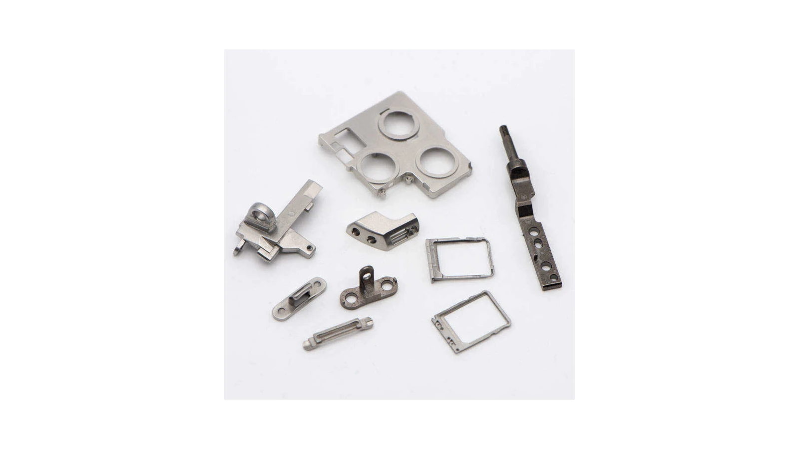
Review a Representative Small Complex Part Example
See the small complex metal part MIM feasibility example for a structured review of geometry, annual demand, machining operations, tolerance split, tooling revision, shrinkage validation, and inspection planning.
The image on the left shows real MIM parts rather than a conceptual illustration. It supports the page by showing the type of compact, feature-dense metal components that are often reviewed for MIM feasibility.
Check Whether a Complex Metal Part Is a Good Candidate for MIM
Complexity alone does not make a part suitable for metal injection molding. A stronger candidate combines compact geometry, stable repeat demand, real metal-performance requirements, and a design that can pass molding, debinding, sintering, inspection, and finishing review.
Strong MIM Signals for Complex Geometry
MIM is usually worth reviewing when a small or medium part combines multiple functional details with repeat production demand and would otherwise require several machining or assembly operations.
Geometry signal
Side holes, grooves, ribs, bosses, curved features, undercuts, multi-level surfaces, or integrated details are difficult to reproduce efficiently by the current route.
Production signal
The design is stable, material requirements are defined, and only selected interfaces need tight secondary control.
Geometry That Needs MIM DFM Redesign
Some parts remain viable only after balancing thick-thin transitions, improving draft and release, opening debinding paths, or moving critical features away from unstable mass zones.
Section-balance risk
Thin ribs beside heavy bosses, abrupt section changes, or isolated local masses can increase shrinkage variation and distortion.
Tooling and access risk
Deep undercuts, negative draft, sharp internal corners, or enclosed features may require tool actions, redesign, or selective machining.
Complex Parts That May Not Belong in MIM
Another route may be more practical when the part is large, simple, extremely low volume, dominated by broad flat geometry, or requires machining-level tolerance across most surfaces.
Usually poor fit
Large simple bodies, long shafts, heavy blocks, broad plates, or frequently changing prototypes with no stable production path.
High conversion risk
Large unsupported thin sections, sealed internal cavities, or drawings that treat nearly every dimension as a critical machined feature.
Information Needed for a Useful Geometry Review
The same geometric feature can be acceptable when cosmetic but high risk when it controls sealing, movement, alignment, wear, or load. Functional context is therefore as important as the 3D model.
Engineering data
2D drawing, 3D model, material grade, annual demand, critical dimensions, surface requirements, current manufacturing route, and expected product life.
Function context
Load paths, mating parts, sealing areas, wear zones, cosmetic surfaces, assembly sequence, post-processing needs, and known failure concerns.
How Common Complex Features Are Reviewed for MIM
The matrix below is a preliminary engineering screen, not a universal pass/fail rule. Final feasibility depends on feature scale, material, tooling direction, wall-thickness balance, debinding path, sintering support, functional tolerance, and inspection access.
| Geometry Feature | Preliminary MIM Status | Main Manufacturing Risk | Likely Engineering Treatment | RFQ Evidence Needed |
|---|---|---|---|---|
| Side hole | Usually reviewable | Core-pull complexity, tool strength, flash, or secondary drilling cost. | Review hole direction, slide action, core support, or leave machining allowance. | Hole diameter, depth, direction, positional tolerance, and functional purpose. |
| Undercut | Conditional | Tool release, ejection damage, added mold action, and maintenance burden. | Use a slider or split tool only when value justifies it; otherwise revise the feature. | Undercut direction, depth, access, mating function, and allowed redesign range. |
| Deep blind hole | High-risk review | Incomplete filling, trapped binder-removal path, core weakness, and inspection difficulty. | Reduce depth, open the feature, alter tooling direction, or machine it after sintering. | Depth-to-diameter requirement, bottom geometry, tolerance, and cleaning requirement. |
| Thin rib beside a heavy boss | Redesign often required | Uneven filling, local density variation, shrinkage mismatch, and distortion. | Balance section transitions, core out the boss, add radii, or move the critical interface. | Rib function, boss load, wall targets, datum structure, and allowed geometry changes. |
| Sealing or locating surface near local mass | High dimensional risk | Local shrinkage drift can move or distort the functional surface. | Separate the CTQ surface from the mass zone or reserve selective sizing or machining. | Datum scheme, flatness, position, seal requirement, and mating-part information. |
| Large unsupported flat area | Often weak fit | Sintering sag, warpage, fixture dependence, and difficult flatness control. | Add stiffness, reduce span, revise the section, or use a different manufacturing route. | Flatness requirement, support surfaces, cosmetic requirement, and assembly constraint. |
| Enclosed internal cavity | Usually unsuitable | Binder removal, cleaning, sintering support, and inspection access may be inadequate. | Open the cavity, split the component, redesign the flow path, or consider additive manufacturing. | Internal access, cleanliness requirement, leak path, inspection method, and assembly options. |
How XTMIM Reviews Complex Geometry MIM Parts Before Tooling
XTMIM reviews the component as one connected manufacturing route rather than a collection of isolated features. Function is mapped first, followed by moldability, debinding, sintering, tolerance allocation, secondary operations, and inspection planning before tooling release.
Drawing Review Starts Before Tooling Release
A useful MIM review begins by reading the part as a functional geometry, not only as a shape. Drawings and 3D models help identify CTQ surfaces, tooling direction, parting-line options, undercuts, local mass concentrations, and the surfaces that should remain near-net-shape or be reserved for secondary finishing.
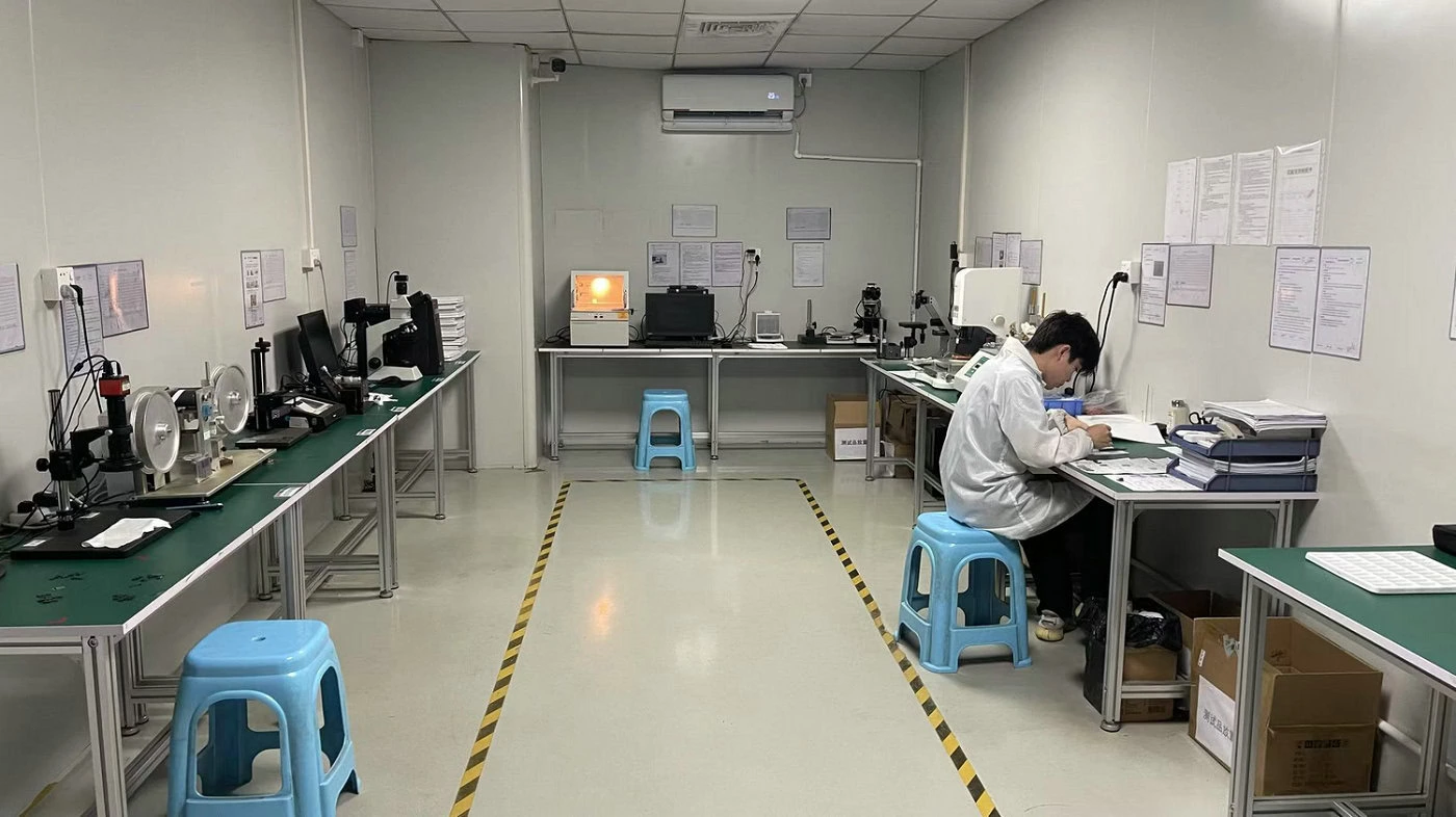
The image on the right is used as a representative engineering illustration for tooling and drawing review. It supports the review logic described on this page and is not presented as a disclosed customer drawing package.

Function Mapping
Identify load paths, mating surfaces, moving features, sealing zones, cosmetic areas, datum logic, and genuinely critical dimensions.
Moldability Review
Check feedstock flow, gate position, parting line, draft, undercuts, slide actions, core strength, ejection, and green-part handling.
Debinding Review
Evaluate local mass, binder-removal paths, blind regions, crack or blister risk, and geometry that may trap defects.
Sintering Review
Review shrinkage direction, support surfaces, warpage risk, mass distribution, and stability of the final datum structure.
Tolerance and Release Plan
Separate as-sintered geometry from CTQ interfaces, then plan sizing, machining, finishing, heat treatment, inspection, and sample release.
Expected Review Output
The review should produce a clear fit decision, required geometry changes, critical-to-quality dimensions, tentative tooling actions, post-processing needs, inspection priorities, and unresolved risks that must be validated during sampling.
Failure Combinations to Resolve Before MIM Tooling
Risk Signals That Become More Serious in Combination
- Heavy local mass beside a thin feature. This can combine filling imbalance with shrinkage and distortion risk.
- Deep blind geometry near an undercut. Tooling, debinding, cleaning, and inspection constraints may accumulate in one area.
- A CTQ surface located in an unstable zone. Sealing, locating, thread, or alignment features should not rely on uncontrolled local shrinkage.
- A broad unsupported surface with strict flatness. Sintering support and secondary correction may become more expensive than another process route.
Inspection Planning Must Follow the Geometry Review
Complex geometry review is incomplete unless the team also decides how the critical features will be checked during sampling and production. Side holes, locating faces, sealing surfaces, threads, and post-processed interfaces should be linked to a practical inspection method before tooling is released.
That is why this page treats tooling review, shrinkage risk, CTQ definition, and inspection planning as one connected decision path rather than separate topics.
When MIM May Be Better Than Machining, Casting, or Assembly
| Decision Area | Typical Problem | How MIM May Help | What Must Be Checked |
|---|---|---|---|
| Small 3D features | CNC requires repeated setups, tool access, drilling, deburring, and inspection. | MIM may form several features through one tooling route. | Gate location, ejection, undercuts, wall balance, tool action, and tolerance split. |
| Part consolidation | Assembly uses several small machined or stamped pieces. | MIM may integrate compatible functions into one compact metal component. | Load path, joining assumptions, sintering distortion, surface access, and inspection method. |
| Material performance | Plastic or some cast routes do not meet required strength, wear, corrosion, or temperature behavior. | MIM supports engineering metal materials for compact functional geometry. | Material grade, density target, heat treatment, corrosion behavior, and finishing route. |
| Tolerance strategy | The drawing treats every feature as equally critical. | MIM can preserve general near-net-shape geometry while selected interfaces receive secondary control. | CTQ dimensions, datum logic, mating surfaces, inspection capability, and post-processing cost. |
| Production demand | Machining is feasible but becomes slow or costly at stable repeat quantity. | MIM may improve repeatability and unit economics after tooling and process validation. | Annual demand, design maturity, product life, tooling cost, sampling, and ramp-up plan. |