
Engineering Process Comparison
Quick Answer
MIM and forging solve different manufacturing problems. Metal injection molding is generally worth reviewing when a part is small, geometrically complex, machining-intensive, and produced in enough volume to justify dedicated tooling. Forging normally remains the stronger starting point when a component has a large load-bearing section, severe impact exposure, demanding fatigue requirements, or performance that depends on deformation-driven grain flow. The decision cannot be made from alloy name, tensile strength, density, or unit price alone. A MIM low-alloy steel and a forged steel with a similar designation may differ in microstructure, defect sensitivity, heat-treatment response, load-direction behavior, and part-level reliability. A sound review should end with one of three outcomes: retain forging, validate a MIM conversion, or use MIM with selected machining. Before choosing, compare the drawing, current route, load spectrum, material condition, critical dimensions, annual volume, inspection plan, and requalification burden.
Choose MIM First When
Geometry Drives the Route
The part is small, feature-rich, machining-intensive, or suitable for one-piece consolidation.
Keep Forging First When
Structural Loading Dominates
The part is large, impact-loaded, fatigue-critical, or dependent on directional material flow.
Review Before Changing
Performance Must Be Revalidated
Compare final material condition, load path, inspection, machining, volume, and qualification burden.
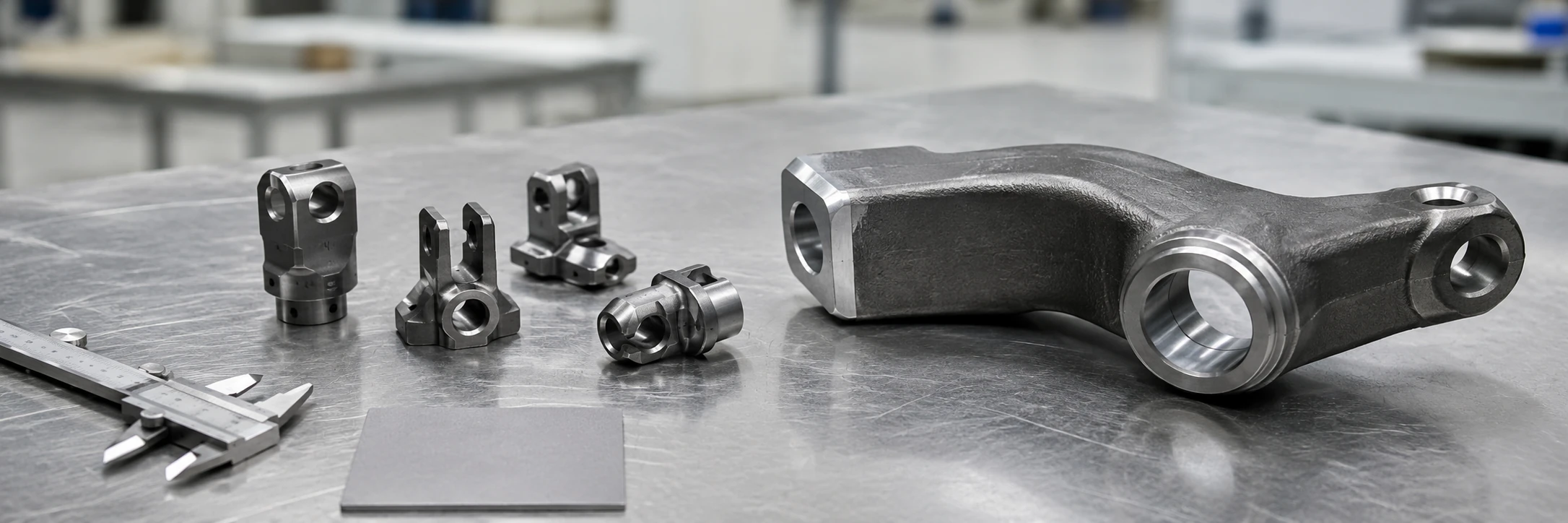
Engineering takeaway: MIM usually creates value through small complex geometry, while forging remains important when section size, impact, fatigue, or directional material structure dominates the decision.
Initial Process Screening
MIM vs Forging at a Glance
The practical difference is not simply that one process forms powder and the other deforms solid metal. Each route creates value under a different combination of geometry, loading, material behavior, production volume, secondary operations, and qualification requirements. This page belongs to the broader MIM vs other processes structure.
| Decision Factor | MIM Usually Deserves Review When | Forging Usually Deserves Review When | Information Still Needed |
|---|---|---|---|
| Part size and mass | The component is small and compact. | The component has a large structural section. | Drawing, weight, and section map. |
| Geometry | The part contains several integrated features. | The main geometry is driven by load-carrying sections. | 3D model and feature review. |
| Loading | Loads are moderate and sufficiently defined. | Impact, shock, or severe cyclic loading dominates. | Load spectrum and duty cycle. |
| Material structure | A sintered material route can be validated. | Directional grain flow contributes to performance. | Material and validation requirements. |
| Machining | The existing route needs extensive drilling, milling, or slotting. | The forged blank needs limited secondary work. | Current operation map. |
| Production volume | Tooling can be amortized over stable demand. | The existing forging route already fits demand. | Annual and lifetime demand. |
| Failure consequence | Performance can be verified with a practical test plan. | Failure is safety-critical or qualification-heavy. | Acceptance and requalification plan. |
Key engineering point: A complex small part is not automatically suitable for MIM, and a high-strength part does not automatically require forging. Tool access, wall transitions, molding behavior, debinding, sintering distortion, heat treatment, machining allowances, and inspection datums still require review.
Use a Three-Gate Review Before Selecting the Route
1. Geometry Gate
Confirm that MIM can form the useful features without creating unbalanced walls, inaccessible tooling, long binder-removal paths, unstable sintering support, or inspection blind spots.
2. Performance Gate
Define the critical section, load direction, duty cycle, impact exposure, fatigue requirement, final heat treatment, surface condition, and acceptance method.
3. Business Gate
Compare complete manufacturing routes, tooling amortization, remaining secondary operations, validation cost, transition risk, design maturity, and lifetime demand.
Tooling Hold Gate
Do not release dedicated MIM tooling merely because the geometry appears moldable. Complete a structured MIM DFM review before tooling release, and require the project to pass all three gates, with unresolved fatigue, impact, material-condition, inspection, or qualification requirements recorded as open actions.
Where MIM Creates Value
Why Small Complex Parts Often Favor MIM
MIM creates value when integrated geometry removes enough machining, joining, or inspection work to simplify the complete manufacturing route. Small size alone is not sufficient.
Multi-Directional Features and Near-Net-Shape Forming
A small forged blank can become expensive after drilling, milling, broaching, slotting, grinding, deburring, and repeated inspection. MIM deserves review when cross holes, grooves, bosses, ribs, flats, pockets, or local thin sections can be formed in or near final geometry. The guide to MIM for small complex parts provides additional geometry-screening context.
Before Tooling, Confirm
- Which features can be molded and which must remain machined.
- Parting line, gate location, and any side-tool actions.
- Wall transitions, binder-removal paths, and sintering support.
- Machining allowances and final inspection datums.
Do Not Assume
- Every undercut can be molded directly.
- Every feature can hold final tolerance as-sintered.
- All post-processing can be removed.
- More feature integration always improves manufacturability.
Reduce Operations, Not Necessary Functional Finishing
A forging remains efficient when it creates a strong shape with limited finishing. MIM becomes more attractive when the current route needs several indexed setups or removes substantial material.
Threads, bearing surfaces, sealing faces, critical bores, tight datums, or demanding finishes may still need machining, grinding, sizing, or threading. The objective is to remove low-value operations while retaining those that protect function.
Part Consolidation Must Remain Manufacturable
A one-piece MIM design may reduce purchased items, joining, tolerance stack-up, and assembly inspection. The consolidated component must still remain moldable, debindable, supportable during sintering, accessible for retained machining, and fully inspectable.
| Current Feature or Operation | Potential MIM Value | Reason It May Still Remain Secondary |
|---|---|---|
| Cross holes and side openings | May be integrated through suitable tooling actions. | Very small, deep, or alignment-critical holes may still require drilling or reaming. |
| Grooves, flats, bosses, and pockets | Can reduce milling setups and material removal. | Tool release, flash control, local wall balance, and datum access must remain practical. |
| Threads | Some thread forms may be molded or prepared near-net shape. | Precision, strength, gauge acceptance, or tool-life requirements may favor tapping or rolling. |
| Bearing, sealing, or locating surfaces | Overall geometry can be molded around the functional surface. | Grinding, sizing, or machining may remain necessary for finish, roundness, or positional control. |
| Multi-piece assembly | One-piece consolidation may reduce joining and tolerance stack-up. | The combined part must remain moldable, supportable during sintering, and fully inspectable. |

Engineering takeaway: MIM becomes valuable when molded geometry can replace several drilling, milling, slotting, joining, or assembly operations.
Where Forging Remains Strong
Why Large, Impact-Loaded or Fatigue-Critical Parts Often Favor Forging
A geometrically producible MIM part is not automatically a technically appropriate replacement for a forging. As structural mass, load severity, fatigue demand, and failure consequence increase, the review must become more conservative.
Large Sections and Load-Carrying Mass
Increasing mass and section thickness can make molding, debinding, sintering, dimensional control, cycle economics, and tooling less favorable. A mainly structural part with limited secondary machining may remain more direct and lower risk as a forging. Use supplier-specific review rather than a universal online size limit.
Impact, Shock and Fracture-Toughness Requirements
Impact-loaded components must absorb energy without unacceptable crack initiation or sudden fracture. Tensile strength alone cannot describe this behavior. Forging may be favored where repeated shock, load reversal, severe notch loading, or high damage tolerance dominates. Directional grain flow can contribute when it follows the load path, although forging quality, heat treatment, and final machining still require control.
High-Cycle or Variable-Amplitude Fatigue
Fatigue depends on surface condition, residual porosity, inclusions, section transitions, machining marks, residual stress, heat treatment, and load direction. A forged-to-MIM change may therefore require part-level cyclic testing, critical-section inspection, material-condition acceptance, and production sampling rather than a datasheet-only comparison.
High Failure Consequences
When failure consequences are severe, an established forging route and its qualification history may outweigh geometry or unit-cost benefits. Conversion cost must include engineering, endurance testing, supplier approval, production validation, and transition risk.
| Stop Sign | Engineering Concern | Initial Direction |
|---|---|---|
| Severe repeated impact | Toughness and crack initiation dominate. | Retain forging unless fully validated. |
| Extreme fatigue requirement | Static strength is insufficient. | Preserve the qualified route. |
| Large structural section | MIM process and economics may be unfavorable. | Review forging first. |
| Grain-flow-dependent design | Directional structure contributes to performance. | Do not assume equivalence. |
| Proven forged component | Conversion creates requalification work. | Change only for a clear benefit. |
| Severe failure consequence | Validation burden may exceed manufacturing savings. | Use a conservative route. |

Engineering takeaway: Forging should remain the leading route when impact, severe fatigue, large structural sections, proven service history, or grain-flow-dependent performance outweigh feature-integration benefits.
Material Structure
Sintered MIM Structure vs Forged Grain Flow
A similarly named MIM and forged alloy should not be treated as automatically interchangeable. Manufacturing route changes how the final component develops density, microstructure, directional behavior, surface condition, residual stress, and defect sensitivity.
How MIM Develops Its Final Structure
MIM begins with fine metal powder mixed with a polymer-based binder. Injection molding creates a green part with the required external and internal geometry. Debinding removes most of the binder, and sintering bonds the powder particles while the component densifies and shrinks.
The final structure depends on powder chemistry and particle characteristics, feedstock consistency, molding conditions, debinding control, sintering atmosphere and temperature, carbon and oxygen control, achieved density, residual porosity, cooling route, heat treatment, and secondary finishing.
How Forging Changes Grain Orientation and Flow
During forging, controlled deformation changes the shape and internal structure of the metal. Properly designed deformation can refine grains and direct grain flow around the component geometry. A forged component may respond differently along and across the grain-flow direction. When the flow follows a critical load path, it may support resistance to fatigue or crack propagation in that direction.
Useful comparison: MIM produces a sintered metallic structure, while forging produces a deformation-processed structure with potentially directional grain flow. Each must be evaluated against the actual part geometry, heat treatment, surface condition, and service load.
Why the Same Alloy Name Does Not Mean the Same Component Behavior
Nominal chemistry does not define the complete component. Manufacturing route affects density, microstructure, grain orientation, inclusions, surface condition, residual stress, heat-treatment response, and defect population. Test-bar data also do not automatically represent performance at a thin wall, notch, bore, transition, or machined critical section.
The article on why the same alloy name can produce different MIM results provides additional material-selection context. For a process conversion, the project team should confirm the exact material specification, test method, heat treatment, density and microstructure requirements, critical load direction, final surface condition, and part-level validation plan.

Engineering takeaway: A sintered MIM structure and a forged grain-flow structure may meet different performance needs even when nominal alloy chemistry appears similar.
Mechanical Performance
MIM Strength vs Forged Steel: Static Strength Is Not Enough
“Strength” may mean tensile or yield strength, hardness, ductility, fatigue, impact resistance, fracture behavior, wear, or performance at a critical section. No single value can establish MIM–forging equivalence.
Datasheets Screen Materials; Parts Prove Performance
Tensile and yield values help eliminate unsuitable routes and identify possible heat treatments, but production geometry changes the comparison. Gate regions, variable sections, threads, holes, machined surfaces, and local stress concentrations can govern the real result.
Ductility, Toughness, Fatigue and Impact
Ductility, toughness, fatigue, and impact describe different behaviors and are not represented by hardness alone. Residual porosity, surface condition, local defects, and notch geometry can influence a sintered part; forged grain-flow orientation can influence directional fatigue behavior. Neither point proves universal superiority. The evidence must match the alloy, process condition, surface, load direction, stress cycle, and acceptance method.
Critical Sections, Load Direction and Final Condition
The review should identify the highest-stress section, principal load direction, notches, contact surfaces, machining transitions, and distortion-sensitive regions. Compare both routes in the final heat-treated, machined, and finished condition. The high-strength MIM materials page can support early screening without replacing part-level verification.
| Requirement | Datasheet Screening Useful? | Part-Specific Verification Usually Needed? |
|---|---|---|
| Tensile strength | Yes | Sometimes |
| Yield strength | Yes | Sometimes |
| Hardness | Yes | Yes after final treatment |
| Impact behavior | Limited | Yes |
| Fatigue life | Limited | Yes |
| Notch-sensitive behavior | Limited | Yes |
| Heat-treatment distortion | No | Yes |
| Critical-section performance | No | Yes |
Build the Validation Plan Around the Failure Mode
A forged-to-MIM conversion should start with the credible failure mode and identify the evidence required at material screening, geometry review, prototype testing, and production acceptance.
| Validation Stage | Questions to Resolve | Typical Evidence | Release Decision |
|---|---|---|---|
| Material-route screening | Can the proposed MIM material and final heat treatment meet the basic static-property and service-environment requirements? | Material specification, published screening data, heat-treatment route, hardness window, corrosion or wear requirement. | Proceed only if the route is technically plausible. |
| Geometry and critical-section review | Where are the highest stress, notch, thin-wall, bore, gate, machining, and distortion-sensitive regions? | 2D drawing, 3D model, load direction, section map, datum plan, simulation or historical failure information when available. | Define prototype geometry, machining allowances, and inspection points. |
| Prototype and part-level testing | Does the actual component meet function under the relevant load, surface, heat-treatment, fatigue, or impact condition? | Dimensional results, density or microstructure criteria where needed, functional testing, endurance testing, fracture review, surface and hardness checks. | Release design and process only after agreed criteria are met. |
| Production acceptance | Can the supplier maintain the critical characteristics consistently across normal production? | Control plan, sampling method, inspection frequency, traceable heat-treatment condition, critical-dimension capability, agreed non-destructive or destructive checks where justified. | Approve production against documented acceptance criteria, not against prototype appearance alone. |
Inspection principle: Concentrate acceptance on characteristics that protect function: the critical section, material condition, justified density or microstructure criteria, surface integrity, dimensional datums, and the actual fatigue, impact, or functional requirement.
Engineering Trade-Off
Geometry Freedom vs Mechanical Performance
MIM creates value when feature integration removes costly operations. Forging creates value when deformation-driven structure and structural continuity support demanding loads.
Geometry Creates More Value
Review MIM when the part is small, multi-featured, machining-intensive, suitable for consolidation, and exposed to defined loads that can be validated.
Reliability Overrides Integration
Keep forging first when grain flow supports the validated design, severe shock or fatigue dominates, the load spectrum is uncertain, or failure consequences are high.
A Hybrid Route Preserves Critical Surfaces
MIM may form the complex body while machining, grinding, sizing, or threading remains only where it protects sealing, bearing, fit, or datum performance.
When Hybrid MIM and Machining Makes Sense
Hybrid processing avoids forcing as-sintered dimensions to carry every precision requirement. Typical retained operations include grinding a bearing diameter, machining a critical bore or datum, cutting a precision thread, correcting a fit surface, or sizing after heat treatment.

Engineering takeaway: MIM should be selected when geometric integration creates more project value, while forging should remain when structural reliability and severe loading control the design.
Conversion Opportunity
When Can MIM Be an Alternative to Forging?
MIM is most credible when the forging route meets the material requirement but produces the final geometry through too many machining, joining, or inspection steps.
Machining Burden and Part Consolidation Create the Opportunity
A small forged part deserves review when several setups remove substantial material or when multiple pieces can be consolidated. Record drilling, milling, grinding, deburring, joining, and inspection, while confirming that the proposed MIM design remains moldable, sinterable, accessible for retained machining, and fully inspectable.
Geometry, Volume and Design Stability Must Support Tooling
MIM creates the most value when feature creation drives more cost than raw material, demand can amortize tooling, and the design is mature. Lifetime demand, cavity count, tool life, expected yield, remaining secondary operations, and requalification cost matter more than annual volume alone.
Compare Total Route Cost, Not Quoted Piece Price
Normalize both quotations to the same finished-part condition. A forged blank price and a MIM piece price are not comparable when operations, inspection, tooling, and validation assumptions differ.
| Cost Block | Forging Route Review | MIM Route Review | Common Comparison Error |
|---|---|---|---|
| Primary forming | Forged blank, trimming, cleaning, forging tooling allocation. | MIM tooling, molding, debinding, sintering, expected process yield. | Comparing only raw blank price with finished MIM price. |
| Secondary operations | Machining setups, grinding, deburring, heat treatment, finishing, assembly. | Remaining machining, sizing, heat treatment, finishing, support or fixture needs. | Assuming MIM removes every secondary operation. |
| Inspection and quality | Current in-process and final inspection, scrap and rework. | Dimensional inspection, material-condition checks, critical-section acceptance, validation sampling. | Ignoring the additional controls needed during conversion. |
| Development and qualification | Existing qualification may already be amortized. | DFM, tooling trials, prototypes, endurance tests, supplier approval, documentation. | Treating requalification as a zero-cost activity. |
| Lifetime and transition risk | Stable route, existing supply chain, known field performance. | Design maturity, demand stability, tool life, ramp-up, dual sourcing or transition inventory. | Using annual volume without lifetime demand or design-change risk. |
Performance Must Be Revalidated Without Unacceptable Risk
The conversion becomes credible only when the geometry, material route, heat treatment, critical dimensions, load conditions, production demand, and requalification plan can all be defined.
- The part is small and compact.
- The current route requires multiple machining operations.
- Complex features are stable enough for repeat production.
- Part consolidation can remove assembly or joining.
- A suitable MIM material route is available.
- Heat-treatment requirements can be controlled.
- Critical dimensions can be inspected.
- Fatigue and impact requirements are defined.
- Production demand can justify tooling.
- Requalification is technically and commercially reasonable.
Review action: The more checklist items remain uncertain, the less reliable an immediate conversion decision becomes.
Conservative Decision Boundary
When Should You Keep Forging?
Retaining forging is often the correct engineering and commercial decision, not a failure to redesign.
Performance Depends on Forged Structure or Severe Loads
Keep forging first when directional grain flow contributes to the validated design, impact or multiaxial loading is severe, fatigue life dominates, or the duty cycle is poorly defined. Similar tensile values do not remove the need for a specific validation plan.
The Existing Route Is Already Qualified
A mature forging may carry field history, endurance data, established acceptance criteria, and an approved supply route. Replace that value only when the manufacturing benefit clearly justifies new tooling, testing, documentation, supplier approval, and production validation.
Size, Volume or Economics Do Not Support Conversion
Large mass, difficult debinding paths, severe section changes, unstable design, low lifetime demand, or limited current machining may leave little advantage for MIM. Use supplier-specific drawing review instead of generic thresholds.
| Current Condition | Recommended Action |
|---|---|
| Small, complex, and machining-intensive with defined moderate loads | Review MIM. |
| Strong geometry fit but fatigue or impact data are incomplete | Review and validate before conversion. |
| Large, simple, highly loaded, or grain-flow-dependent | Keep forging. |
| Low volume with an unstable design | Delay dedicated MIM tooling. |
| Proven forging with limited machining and high requalification burden | Keep the current route. |
| Complex geometry with only a few critical precision surfaces | Review hybrid MIM plus machining. |
Terminology Boundary
MIM, Forging and Powder Metallurgy Are Not the Same Comparison
MIM belongs to the broader powder metallurgy family, but “forging vs powder metallurgy” is not identical to “MIM vs forging.” Conventional press-and-sinter PM compacts powder in a rigid die and is strongly influenced by compaction direction, tool access, and density distribution. MIM injection molds powder-and-binder feedstock before debinding and sintering, enabling a different range of small complex geometries. Powder forging is another distinct route.
This page compares metal injection molding with forged-part production. Projects comparing forging with conventional die-compacted PM should use the dedicated MIM vs PM comparison rather than treating every powder-based process as one category.
Applied Decision Sequence
Representative Engineering Scenario
Consider a small heat-treated low-alloy steel component made from a forged blank. It has a cross hole, offset slot, local flats, locating boss, and ground functional diameter. The current route uses forging, heat treatment, multiple drilling and milling operations, grinding, deburring, and final inspection, so MIM appears attractive for feature integration.
The component also sees cyclic loading and occasional local impact, while the available data do not define the fatigue spectrum or impact acceptance. The process cannot be changed on geometry alone.
What Initially Favors MIM
- Small, compact component.
- Several multi-directional features.
- Multiple current machining operations.
- Only selected surfaces may need grinding.
What Must Be Resolved First
- Critical section and actual load direction.
- Contribution of forged grain flow.
- MIM material and heat-treatment condition.
- Fatigue, impact, surface, and critical-section acceptance.
Engineering decision: MIM may reduce machining, but conversion should proceed only after load, fatigue, heat-treatment, inspection, and production-volume requirements are defined.
Recommended Hold Gates
- Before DFM approval: confirm the critical section, load direction, surface condition, and features that genuinely remove machining.
- Before tooling release: define material condition, heat treatment, machining allowances, inspection datums, fatigue or impact acceptance, and volume.
- Before production approval: verify dimensions, material condition, critical-section integrity, functional performance, and repeatability against documented criteria.
Qualified Project Input
What to Send for a Forged-Part-to-MIM Review
A useful supplier review requires more than a request for price. The drawing, current route, material condition, service loads, production demand, inspection, and validation requirements must be reviewed together.
Expected review output: The supplier response should identify whether to keep forging, evaluate MIM, or consider a hybrid route; which features can be molded; which operations should remain; what material and heat-treatment route is proposed; what evidence is required before tooling; and which assumptions still need customer confirmation.
Drawing and Geometry Files
- 2D drawing and 3D CAD model.
- Current part weight.
- Forged blank drawing, if available.
- Critical and reference dimensions.
- Geometric tolerances and surface finish.
- Threads, bores, seals, and bearing surfaces.
Current Forging and Machining Route
- Forging type or current blank route.
- Trimming or cleaning operations.
- Machining setups and operations.
- Grinding, sizing, deburring, or joining.
- Surface treatment.
- Current inspection stages.
Material and Heat Treatment
- Current material specification and condition.
- Review available heat-treatable MIM materials against the required heat-treatment route, target hardness, toughness, distortion, fatigue, and inspection requirements.
- Case-depth requirement, if applicable.
- Wear, corrosion, or temperature requirements.
- Restricted materials or processing conditions.
Load, Volume and Validation
- Principal load direction and maximum working load.
- Duty cycle, expected service life, fatigue, and impact.
- Annual volume and expected project life.
- Critical-to-function dimensions.
- Inspection, endurance, and qualification requirements.

Engineering takeaway: A reliable comparison requires the drawing, current material and heat treatment, machining route, volume, load direction, fatigue or impact requirements, critical dimensions, and inspection plan.
Request a Forged-Part-to-MIM Feasibility Review
Send the 2D drawing, 3D model, current forged material, heat-treatment condition, annual volume, current machining operations, critical dimensions, load direction, fatigue or impact requirement, surface condition, and inspection criteria. The review should determine whether MIM is technically and commercially worth evaluating or whether the forged route should remain unchanged.
Common Engineering Questions
Frequently Asked Questions
Is MIM as strong as forged steel?
Some MIM materials can provide high tensile strength, yield strength, and hardness after an appropriate heat treatment. That does not make every MIM component equivalent to a forged component. Fatigue, impact, fracture behavior, residual porosity, surface condition, grain-flow direction, geometry, and heat treatment must be considered separately.
Can MIM replace a forged steel part?
MIM can be considered when the part is small, complex, machining-intensive, and required in stable production volume. Conversion is less appropriate when the part is large, impact-loaded, fatigue-critical, grain-flow-dependent, or expensive to requalify. A drawing and load review is required before making the decision.
Why does forging often perform well under impact or fatigue?
Controlled plastic deformation can refine the structure and create grain flow that follows the component geometry. When the grain flow aligns with the load path, it may support directional fatigue and fracture performance. The result still depends on forging design, process quality, heat treatment, surface condition, and final machining.
Why is MIM useful for small complex parts?
MIM can form several features in one molding cycle and may reduce drilling, milling, slotting, joining, and assembly. Its value increases when geometry and downstream operations drive the cost. The part must still meet molding, debinding, sintering, distortion, and inspection requirements.
Is forging vs powder metallurgy the same as forging vs MIM?
No. Powder metallurgy includes several different processes. Conventional press-and-sinter PM, MIM, and powder forging use different forming methods and have different geometry and material characteristics. This comparison focuses specifically on MIM versus forged-part production.
What information is needed to compare MIM with forging for my part?
Provide the 2D drawing, 3D model, current forged material, heat-treatment condition, current machining route, annual volume, load direction, fatigue and impact requirements, critical dimensions, surface requirements, inspection method, and validation requirements.
Engineering Background
Technical References
The following non-competitor sources support the process and material-structure boundaries discussed on this page. They do not certify, approve, or endorse XTMIM or any specific project.
- Metal Powder Industries Federation: Metal Injection Molding — Background on fine metal powder, binder, injection molding, debinding, sintering, and complex-shape production.
- Forging Industry Association: Product Design Guide for Forging — Engineering background on forging design, deformation, grain flow, and directional properties.
- Influence of Grain-Flow Orientation after Hot Forging Evaluated through Rotational Flexing Fatigue Testing — Primary research relevant to grain-flow orientation and fatigue behavior.
- MPIF: Materials Standards for Metal Injection Molded Parts—2025 Edition — Current official edition notice for standardized MIM material terminology and property screening.