
Choose MIM, CNC, or a Hybrid Manufacturing Route?
Choose MIM when a small, complex metal part has stable production demand and its CNC cost is driven by repeated multi-axis machining, material removal, deburring, or inspection. Choose CNC for prototypes, low-volume production, frequent design changes, large simple geometries, or parts that require tight machined control across many functional surfaces. A hybrid MIM + CNC route is often the best production decision when MIM can form the complex body near net shape while CNC is retained only for critical holes, threads, datum faces, bearing fits, or sealing surfaces. The decision should be based on project-life volume, geometry, tolerance classification, material conversion, secondary machining, and the calculated cost crossover—not on unit price alone.
This page belongs to the XTMIM MIM comparison cluster and evaluates process selection for small complex metal parts. It does not present MIM as a universal replacement for CNC machining.
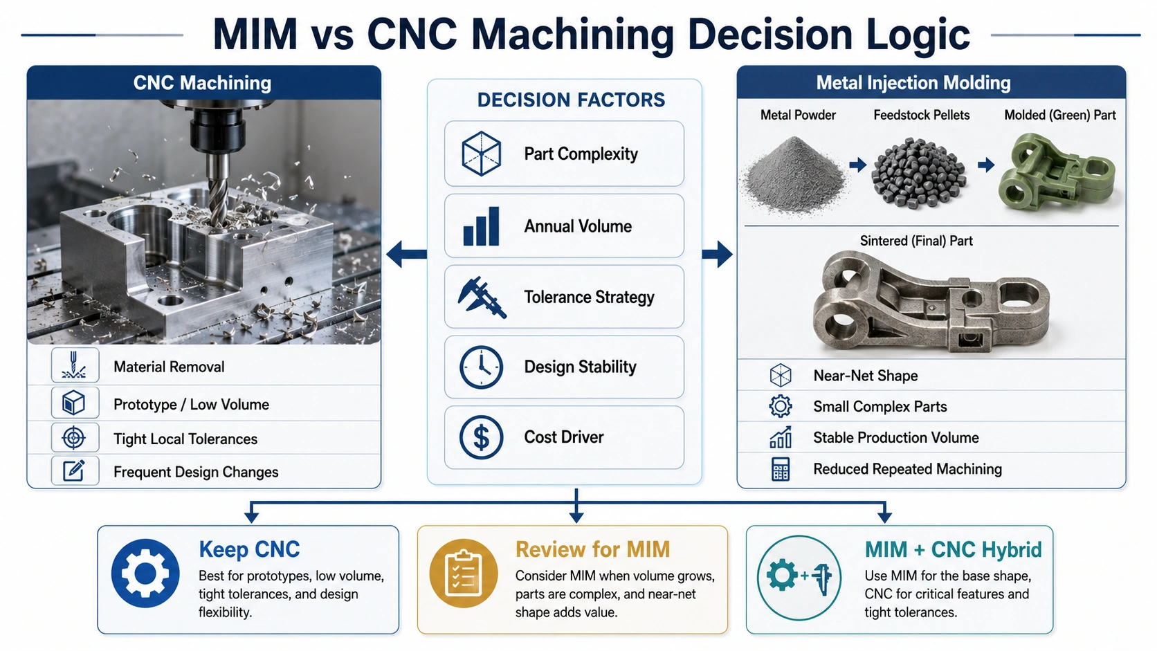
MIM vs CNC: Different Ways of Creating Cost and Precision
The main difference is not simply molding versus machining. CNC creates geometry and tolerance by removing material directly from a controlled datum structure, while MIM forms the geometry first and controls final dimensions through tooling compensation, green-part stability, debinding, sintering shrinkage, and selected secondary operations. That difference changes where cost occurs, how design changes are handled, and which dimensions should remain machined.
CNC: Flexible, Direct, and Strong for Local Precision
CNC machining removes material from bar, plate, billet, casting, forging, or other solid stock. It is usually the stronger route for prototypes, low-volume production, frequent design changes, simple tool-accessible geometry, and parts with many tightly controlled local surfaces. Its limitation in repeat production is that setup, toolpath time, tool wear, material removal, deburring, and inspection recur on every part.
MIM: Tooling-Based Near-Net Shape for Repeatable Complexity
MIM injection molds metal-powder feedstock, removes the binder, and sinters the part to final density and dimensions. It is strongest when small complex geometry can be formed near net shape across stable production demand. The trade-off is higher upfront tooling and validation work, plus the need to manage shrinkage, distortion, material conversion, and any critical features that still require machining.
Decision implication: Use CNC when flexibility and direct dimensional control matter most. Review MIM when repeatable complexity creates recurring machining cost. Use a hybrid route when the complex body can be molded but selected functional surfaces still require CNC finishing.

Core conclusion: CNC and MIM do not create dimensions in the same way. CNC cuts directly from solid stock; MIM forms the shape first and then controls shrinkage during sintering.
MIM vs CNC Comparison: Cost, Volume, Geometry, and Tolerance
Use this table to screen the manufacturing route before detailed DFM or quotation. No single factor decides the result: a suitable process must align geometry, project-life volume, tolerance strategy, material requirements, design maturity, secondary operations, and inspection cost.
On mobile, scroll horizontally to compare details.
| Factor | MIM | CNC Machining | Engineering Decision |
|---|---|---|---|
| Best part type | Small complex metal parts with repeatable geometry | Prototypes, low-volume parts, precision-machined components | Match the process to geometry, tolerance, design maturity, and production volume. |
| Cost structure | Higher upfront tooling and validation cost, with lower repeat production potential when the part is suitable | Lower upfront cost, but repeated machining cost per part | MIM needs stable volume and sufficient CNC cost pressure to justify tooling. |
| Geometry | Strong for complex 3D features, thin sections, small ribs, and near-net-shape forms | Strong for tool-accessible features and directly machined surfaces | CNC becomes costly when many complex features repeat on every part. |
| Volume | Better for stable medium-to-high volume | Better for prototype, low volume, or uncertain demand | Volume is a key crossover factor, but geometry and tolerance can change the decision. |
| Tolerance | Good for suitable features; critical areas may need machining or sizing | Strong for tight local machined tolerances | Do not assume MIM can replace CNC tolerance on every surface. |
| Design changes | Tooling changes can be expensive | Toolpaths and fixtures can often be changed more easily | CNC is better before design freeze. |
| Material waste | Lower material waste for suitable near-net-shape production | Higher when cutting complex geometry from solid stock | MIM can help when material removal is high, but material availability must be checked. |
| Lead time | Longer upfront due to tooling, sampling, and process validation | Faster for prototypes and early samples | CNC is usually faster before production tooling. |
| Secondary operations | May be needed for threads, holes, datum surfaces, flatness, or tight fits | Built into the manufacturing route | Many production projects use MIM + CNC together. |
| Inspection strategy | Requires control of shrinkage, distortion, density, surface condition, and critical features | Requires inspection of machined dimensions and surface requirements | Inspection plan should follow the selected manufacturing route and critical-to-function features. |
MIM vs CNC Cost Crossover: Calculate the Break-Even Quantity
The cost crossover is the production quantity at which the cumulative cost of MIM becomes comparable to or lower than the cumulative cost of CNC. It should be calculated from delivered manufacturing cost—not from machining time or quoted unit price alone—and then checked against design stability, project life, tolerance risk, material conversion, and required secondary operations.
CNC Cost Repeats on Every Part
CNC machining cost is not only the price of machine time. It may include material stock, programming, setup, fixtures, tool wear, cutting time, deburring, surface finishing, inspection, scrap risk, and packaging. For a simple part, this may be acceptable. For a small complex part with many repeated details, the same cost drivers occur again and again.
A common cost problem appears when a part is stable in design but still depends on slow machining. If the part requires multiple orientations, small cutters, deep features, side holes, thin walls, or extensive manual deburring, the cost may not drop enough even when quantity increases. This is the point where MIM should be reviewed as a production route, not as a prototype route.
MIM Shifts More Cost into Tooling and Validation
MIM requires tooling. It also requires engineering work before production: mold design, gate and parting-line review, shrinkage compensation, sampling, debinding and sintering control, dimensional review, and inspection planning. These costs must be justified by production volume and part complexity.
For this reason, MIM is usually weak for prototypes, one-time builds, unstable designs, or projects with uncertain demand. It becomes stronger when the same geometry will be produced repeatedly and the tooling investment can be spread across the project life. For a dedicated cost breakdown, read the XTMIM guide to metal injection molding cost.
Break-Even Quantity Formula
Break-even quantity = MIM upfront tooling and validation cost ÷ (CNC delivered unit cost − MIM recurring delivered unit cost)The denominator is the recurring saving per part after the MIM route is validated. If the CNC delivered unit cost is not higher than the MIM recurring delivered unit cost, the formula does not produce a useful crossover and MIM should not be justified on cost alone.
Illustrative Calculation
Assume a representative project has USD 24,000 in MIM tooling and validation cost, a CNC delivered cost of USD 18 per part, and a recurring MIM delivered cost of USD 6 per part. The recurring saving is USD 12 per part, so the calculated break-even quantity is 2,000 parts. If secondary machining raises the MIM recurring cost to USD 9 per part, the saving falls to USD 9 and the crossover moves to about 2,667 parts.
This arithmetic is an illustrative engineering scenario, not an XTMIM quotation or a universal industry threshold. Replace every input with the actual drawing-based tooling, validation, machining, finishing, inspection, scrap, and project-life assumptions for the part under review.
Decision rule: Project-life demand should exceed the calculated break-even quantity with a reasonable margin. A mathematical crossover alone is not enough if the design is still changing, the material conversion is uncertain, most functional surfaces still require CNC machining, or tooling revision risk is high.
Do Not Compare Only Unit Price
A common sourcing mistake is comparing one CNC unit price with one MIM unit price without reviewing the full cost model. A useful comparison should include annual volume, expected project life, tooling amortization, material waste, secondary machining, inspection requirements, finishing steps, scrap risk, and the cost of future design changes.
Cost Review Inputs for MIM vs CNC
Before deciding whether MIM can reduce cost, the review should connect cost drivers with drawing requirements. A lower theoretical unit price is not useful if the part still requires extensive secondary machining, difficult inspection, or material conversion risk. For the drawing, tolerance, material, volume, finishing, and inspection inputs needed for this calculation, review the drawing data required for a MIM vs CNC cost review.
On mobile, scroll horizontally to compare details.
| Input | Why It Matters | What to Provide |
|---|---|---|
| Annual volume | Determines whether tooling, sampling, and validation can be justified. | Estimated yearly demand, forecast range, or project life volume. |
| Current CNC cost driver | Identifies whether MIM can reduce repeated machining work. | Cycle time, number of setups, deburring workload, scrap concern, or cost bottleneck. |
| Critical tolerance zones | Determines whether secondary CNC machining remains necessary. | 2D drawing with marked critical dimensions, datums, fits, and flatness areas. |
| Material requirement | Confirms whether MIM material conversion is feasible. | Current CNC alloy, required properties, heat treatment, coating, or application environment. |
| Expected project life | Affects tooling amortization and production route selection. | Program duration, purchase forecast, or expected production stability. |

Core conclusion: MIM does not win because it is always cheaper. It becomes competitive when repeated CNC cost drivers can be replaced by tooling-based near-net-shape production.
When MIM Becomes Better Than CNC
Repeated CNC Features Drive Machining Cost
MIM becomes worth reviewing when CNC cost is driven by repeated features rather than by one simple cut. Examples include small slots, cross holes, grooves, curved surfaces, side features, bosses, ribs, micro-geometries, or features that require multiple tool approaches.
In CNC machining, every feature must be accessed, cut, deburred, and inspected. If the same complexity repeats across production volume, molding the geometry near-net shape may reduce the dependency on repeated machining.
Need a practical conversion example? For a representative engineering example showing how a small complex metal part can be reviewed for MIM, including part size, annual volume, CNC operations, tolerance split, shrinkage validation, tooling revision, secondary machining and inspection planning, see this small complex CNC-to-MIM conversion example.
Complex 3D Geometry Can Be Molded Near-Net Shape
MIM is especially valuable when the geometry is difficult to machine but practical to mold and sinter. This includes small metal parts with complex external profiles, compact structural forms, thin sections, small projections, and features that would require several CNC setups.
Near-net shape does not mean zero finishing. It means the main geometry is formed close to final shape, reducing the amount of material removal needed after sintering.
Stable Production Volume Can Justify Tooling
MIM tooling makes sense only when the design is mature enough and the expected production volume is stable enough. If the drawing changes frequently, CNC is safer because toolpaths and fixtures can often be adjusted more easily than production tooling.
MIM Can Reduce Material Waste and Repeated Deburring
CNC machining removes material from solid stock. For complex parts, a large amount of material may be cut away, especially when the final component is small relative to the starting stock. MIM forms the part closer to final geometry and may reduce material waste.
Deburring is another important cost driver. Small machined edges, cross holes, and internal features may require manual or controlled deburring. When MIM can form these features more directly, the production route may become more efficient. However, MIM parts still require their own quality controls, including gate area review, green part handling, sintering distortion control, and surface condition inspection.
When CNC Machining Is Still the Better Choice
Prototype and Low-Volume Parts
CNC machining is usually better for prototypes and low-volume projects because it does not require MIM tooling. If the design is still being tested, CNC allows engineers to change dimensions, materials, and features with less tooling risk.
Frequent Design Changes
MIM tooling should not be started when the product design is still unstable. Changes to wall thickness, hole locations, datum strategy, or functional interfaces may require mold modification or even new tooling.
Very Tight Local Tolerances on Many Surfaces
MIM can provide good dimensional consistency for suitable features, but it should not be described as the same as CNC machining. CNC controls dimensions by direct cutting from defined datums and remains stronger for many critical local fits.
Large or Simple Block-Like Parts
MIM is usually not the best route for large simple parts or block-like components with only basic holes and milled surfaces. The advantages of MIM are strongest when the part is small, complex, and repeatedly produced.
MIM + CNC: The Hybrid Route Many Projects Actually Need
MIM Forms the Complex Body
Many successful MIM conversion projects do not remove CNC completely. Instead, MIM is used to form the complex body of the part: curved profiles, ribs, bosses, compact 3D structures, repeated features, and near-net-shape geometry that would be expensive to machine repeatedly.
CNC Finishes Critical Functional Areas
CNC machining may still be used after MIM for features that require tighter local control. These may include precision holes, bearing seats, threads, mating faces, datum surfaces, sealing areas, or flat functional surfaces.
This is not a failure of MIM. It is often the correct manufacturing strategy. MIM provides the near-net-shape base, while CNC is reserved for features where direct machining is technically or economically justified.
Machining Allowance Must Be Planned Before Tooling
If secondary CNC machining is required, it should be planned before MIM tooling begins. The mold design, shrinkage compensation, part geometry, and inspection plan may need to allow extra material for machining. This topic connects directly with MIM secondary operations and early MIM design guide review.
A common mistake is deciding on secondary machining only after sintering problems appear. By that point, the geometry may not have enough stock allowance, the datum strategy may be unclear, or the machining fixture may be difficult to design. For MIM conversion projects, secondary machining should be part of the initial DFM review.

Core conclusion: MIM vs CNC is not always a binary decision. Many production parts use MIM for the complex body and CNC only where direct precision machining is required.
Tolerance and Dimensional Control: MIM Is Not CNC
CNC Controls Dimensions by Direct Machining
CNC machining controls dimensions by cutting directly from solid material. The process can reference datums, control local features, and finish functional surfaces with high precision when the part is properly fixtured and inspected.
MIM Controls Dimensions Through Tooling and Sintering Stability
MIM controls dimensions through a different route. The mold is designed with shrinkage compensation, the green part must be handled properly, binder must be removed without damage, and sintering must be controlled to achieve stable final dimensions.
Several factors can influence dimensional results, including wall thickness variation, local mass concentration, gate position, support during sintering, feature orientation, material system, and post-sintering operations. These factors do not make MIM unreliable, but they do mean that MIM tolerances must be reviewed differently from CNC tolerances.
Critical Dimensions Should Be Classified Before Process Selection
On mobile, scroll horizontally to compare details.
| Dimension Type | Recommended Review Strategy |
|---|---|
| General profile dimensions | Review whether as-sintered MIM tolerance is suitable. |
| Tight bearing hole | Consider MIM forming plus CNC finishing. |
| Internal thread | Review whether molded, tapped, or machined thread is more reliable. |
| Datum surface | Confirm whether machining is required after sintering. |
| Flat sealing surface | Review flatness risk and possible secondary finishing. |
| Cosmetic surface | Confirm surface condition, finishing method, and inspection criteria. |
| Thin wall or long feature | Review distortion risk during debinding and sintering. |

Core conclusion: MIM can provide stable dimensions for suitable features, but it should not be presented as CNC-level precision on every surface. Critical dimensions must be classified before process selection.
How a CNC Drawing Should Be Reviewed Before MIM Tooling
Identify Critical-to-Function Dimensions
A CNC drawing often contains many dimensions, but not all dimensions have the same functional importance. Before MIM tooling, the engineering team should identify which dimensions control assembly, movement, sealing, load transfer, alignment, or safety.
Critical-to-function dimensions should receive special review. They may need tighter inspection, secondary machining, a modified datum strategy, or design changes before tooling.
When the project has moved beyond general process comparison and the team is evaluating an actual production change, use the CNC-to-MIM conversion review to assess geometry redesign, tolerance split, secondary machining, material conversion, tooling risk, and production scaling.
Separate As-Sintered Dimensions from Machined Dimensions
Not every feature should be machined after MIM. The purpose of MIM is to reduce unnecessary machining, not to create a molded blank that still requires full CNC processing.
From a design review perspective, dimensions should be classified as suitable for as-sintered MIM, suitable after minor secondary operation, requiring CNC finishing, requiring design modification, or not suitable for MIM without significant risk.
Review Holes, Threads, Datums, Sealing Surfaces, and Bearing Fits
Features that are easy to machine are not always easy to mold and sinter. Holes, threads, datum surfaces, sealing areas, and bearing fits should be reviewed carefully.
For example, a tight hole may be formed near-net shape and then machined. A thread may be molded, tapped, or machined depending on size, load, and tolerance. A sealing surface may require secondary finishing even if the rest of the part is molded successfully.
Check Wall Thickness, Transitions, Undercuts, and Local Mass Concentration
MIM is sensitive to geometry balance. Thick-to-thin transitions, local mass concentration, sharp corners, unsupported thin features, and long flat sections may increase the risk of distortion, cracks, sink, short shot, or dimensional variation.
A good MIM review does not only ask whether the shape can be molded. It asks whether the part can be injection molded, handled as a green part, debound, sintered, inspected, and produced consistently.
Confirm Whether the CNC Material Can Be Replaced by a MIM Material
The material used for CNC machining may not always have a direct MIM equivalent. Even when a similar alloy family exists, the final properties depend on feedstock availability, sintering response, heat treatment, surface finishing, and the supplier’s process capability. For material options, see MIM materials.
Material conversion should be reviewed based on application requirements, not only material name. Strength, corrosion resistance, wear resistance, magnetic behavior, heat resistance, surface treatment, and customer specifications may all affect the decision.

Core conclusion: A CNC drawing should not be copied directly into MIM tooling. It must be reclassified by function, tolerance, material, and secondary machining needs.
Composite Field Scenario for Engineering Training
What Problem Occurred
A small CNC-machined metal component appeared suitable for MIM because the outer shape was compact and the current machining route required several setups. During review, the team found that the drawing treated all holes, the main datum face, and a bearing-fit feature as if they could be copied directly into MIM tooling without secondary machining allowance.
Why It Happened
The project was evaluated mainly from the part shape and unit-cost pressure. The original CNC drawing did not separate functional dimensions from general profile dimensions. It also did not identify which surfaces were allowed to be as-sintered and which surfaces still needed direct machining after sintering.
What the Real System Cause Was
The real issue was not only tolerance. The system problem was missing process translation between CNC and MIM. CNC creates dimensions by direct machining from datums, while MIM requires tooling compensation, green part stability, debinding, sintering shrinkage control, and planned secondary operations. Without this translation, the MIM tool could have been built without enough machining stock or a reliable datum strategy.
How It Was Corrected
The drawing was reclassified into as-sintered features, CNC-finished features, and review-required features. The bearing-fit hole and datum face were assigned to secondary CNC machining. Machining allowance was added before tooling, and the inspection plan was adjusted to verify both as-sintered dimensions and machined functional areas.
How to Prevent Recurrence
Before tooling, every CNC-to-MIM project should classify critical-to-function dimensions, define secondary machining zones, confirm material conversion, review wall thickness balance, and agree on the inspection method. This prevents the project from treating MIM as a simple copy of a CNC drawing.
Typical CNC Parts Worth Reviewing for MIM Conversion
The following examples are not automatic MIM candidates. They are common CNC part conditions that are worth reviewing when geometry, volume, tolerance, and material requirements make repeated machining expensive.
On mobile, scroll horizontally to compare details.
| CNC Part Condition | Why MIM May Help | What Still Needs Review |
|---|---|---|
| Small bracket with multiple side features | May reduce repeated multi-axis machining and deburring. | Datum faces, flatness, hole tolerance, and sintering distortion risk. |
| Miniature gear or toothed component | May form complex tooth profiles or compact geometry near-net shape. | Wear resistance, heat treatment, bore finishing, and functional fit. |
| Compact hinge or rotating part | May form bosses, curved geometry, and repeated small features efficiently. | Pin hole tolerance, bearing fit, friction surface, and secondary machining allowance. |
| Sensor, connector, or small metal insert | May reduce repeated machining of compact details and internal forms. | Material conversion, plating, surface condition, and dimensional stability. |
| Precision instrument subpart | May reduce repeated machining for small complex structural forms. | Material standard, cleaning requirement, inspection method, and functional dimensions. |
Part Suitability Matrix: Strong, Borderline, or Weak MIM Candidate
Strong MIM Candidate
A strong MIM candidate is usually a small complex metal part with stable production volume, repeated CNC features, difficult deburring, and enough geometric complexity to justify tooling. The part should not require CNC-level tolerance on every surface.
- Compact metal component
- Complex 3D geometry
- Stable annual volume
- High CNC cycle time
- Limited critical machining areas
- Design close to freeze
Borderline Candidate
A borderline candidate may still be suitable for MIM, but it requires deeper review. The part may have some tight tolerances, uncertain volume, possible design changes, or features that require secondary CNC machining.
Borderline projects should not be rejected too early, but they should not be quoted casually either. The correct next step is a drawing-based process suitability review.
Weak MIM Candidate
A weak MIM candidate is usually a prototype, very low-volume part, large simple component, frequently changing design, or part with tight machined tolerance requirements on most surfaces.
If CNC machining is already simple, fast, and cost-effective, MIM may add unnecessary tooling cost and process risk.

Core conclusion: Not every CNC part should be converted to MIM. Suitability depends on the combined effect of complexity, volume, tolerance, material, and production stability.
Inspection Points After MIM Conversion
Dimensional Inspection
After converting a CNC part to MIM, the inspection plan should identify which dimensions are as-sintered, which are secondary machined, and which are critical to function. General profile dimensions, local fits, datum relationships, and flatness may need different inspection methods.
Density and Material Condition
MIM parts should be reviewed for material condition based on the selected alloy, feedstock, sintering process, and application requirements. Density, strength, hardness, corrosion resistance, magnetic behavior, or heat treatment response may be relevant depending on the part.
Surface Condition
Surface condition may affect assembly, sealing, friction, wear, plating, passivation, cosmetic appearance, or cleaning requirements. MIM surface expectations should be reviewed before tooling, especially if the CNC part currently has a machined finish.
Distortion and Flatness Risk
Thin walls, long sections, uneven wall thickness, local heavy sections, and unsupported features can increase distortion risk during debinding and sintering. These risks may require design changes, sintering support, secondary operations, or tolerance adjustment.
Secondary Machining Verification
If CNC machining is retained after MIM, the inspection plan should verify machined dimensions, datum locations, fixture strategy, and allowance control. The MIM part should be designed so the secondary machining operation is stable and repeatable.

Core conclusion: MIM conversion is not complete when the part shape is molded. Dimensional, material, surface, distortion, and secondary machining checks must be planned before production.
Design Review Checklist Before Converting CNC Parts to MIM
Geometry Review
- Is the part small enough and complex enough to justify MIM?
- Are there thin walls, deep grooves, ribs, bosses, side features, or undercuts?
- Are wall thickness transitions balanced?
- Are there long unsupported sections that may distort?
- Can the part be molded, debound, and sintered consistently?
Tolerance Review
- Which dimensions are critical to function?
- Which dimensions can be as-sintered?
- Which features require CNC finishing?
- Are datum surfaces clearly defined?
- Are tolerance requirements realistic for the selected process route?
Material Review
- What is the current CNC material?
- Is an equivalent or suitable MIM material available?
- Are strength, corrosion, wear, magnetic, or heat resistance requirements defined?
- Is heat treatment required?
- Are there customer or application-specific material requirements?
Secondary Machining Review
- Which holes, threads, bearing seats, sealing surfaces, or datums need machining?
- Is machining allowance included in the MIM design?
- Can the sintered part be fixtured reliably?
- Does secondary machining remove the expected MIM cost advantage?
- How will machined features be inspected?
What Information Should You Send for a MIM vs CNC Review?
A useful MIM vs CNC review should be based on drawings and project requirements, not only part photos. To evaluate whether a CNC-machined component is suitable for MIM, the engineering team should review both geometry and production context. For a more complete submission checklist, see the XTMIM RFQ preparation guide.
Recommended Project Information
- 2D drawing with tolerances
- 3D CAD file
- Current CNC material
- Required material properties
- Annual volume or estimated production quantity
- Current CNC cost concern
- Critical dimensions and functional features
- Surface finish requirements
- Heat treatment, plating, passivation, or coating needs
- Application environment and assembly function
- Known quality problems or production bottlenecks
With this information, XTMIM can review whether your part is a strong MIM candidate, a hybrid MIM + CNC candidate, or better kept as CNC machining.
What XTMIM Can Review Before RFQ
A useful MIM vs CNC review should provide engineering direction before price discussion. The goal is to identify whether the project is suitable for MIM, which features need further review, and what information is missing before quotation or tooling.
Process Suitability
- Whether the CNC part is a strong, borderline, or weak MIM candidate
- Whether the geometry can be molded, debound, sintered, and inspected consistently
- Whether the project should remain CNC, move to MIM, or use a hybrid MIM + CNC route
Feature Classification
- Which features may remain as-sintered
- Which holes, threads, datums, bearing fits, or sealing areas may need CNC finishing
- Where machining allowance should be planned before tooling
Material and Quality Risk
- Whether CNC material conversion to MIM is practical
- Where distortion, shrinkage, surface, or sintering support risks may appear
- Which material, heat treatment, or surface requirements need confirmation
RFQ Readiness
- What information is still missing before quotation
- Which tolerances or functional requirements need clarification
- Whether the cost comparison should include tooling, secondary machining, inspection, and MIM unit-cost review
Standards & Technical References Note
MIM vs CNC process selection should be based on part geometry, material requirements, tolerance strategy, production volume, and application conditions. General industry references such as MIMA design resources, the EPMA metal injection moulding overview, and MPIF Standard 35-MIM material references can help frame the engineering review.
These references should not be used as a substitute for project-specific evaluation. Final decisions should be confirmed against the customer drawing, material data, application requirements, inspection plan, supplier process capability, and any applicable customer or industry specifications. For critical applications, material selection, dimensional requirements, heat treatment, surface condition, and inspection criteria should be agreed before tooling.
MIM vs CNC FAQ
Is MIM cheaper than CNC machining?
MIM is not always cheaper than CNC machining. MIM is more likely to reduce cost when the part is small, complex, stable in design, and produced in meaningful volume. If CNC cost is driven by repeated machining operations, material waste, deburring, or inspection, MIM may be worth reviewing. For prototypes, low-volume projects, or frequently changing designs, CNC is usually more practical.
Can MIM replace CNC completely?
Sometimes yes, but not always. Many successful projects use MIM to form the complex near-net-shape body and keep CNC machining only for critical holes, threads, datum surfaces, bearing fits, or sealing surfaces. The best route depends on tolerance requirements, geometry, material, and production volume.
Is MIM as accurate as CNC machining?
MIM and CNC control dimensions in different ways. CNC directly machines dimensions from solid stock and is usually stronger for very tight local tolerances. MIM can provide stable dimensional results for suitable features, but it depends on tooling compensation, debinding, sintering shrinkage, support strategy, and inspection planning. Critical dimensions should be reviewed before process selection.
What volume makes MIM worth considering?
There is no universal volume threshold. Calculate the break-even quantity by dividing MIM tooling and validation cost by the difference between CNC delivered unit cost and MIM recurring delivered unit cost. Then confirm that project-life demand exceeds that crossover with enough margin to absorb tooling revisions, scrap, inspection, finishing, and secondary machining. Geometry, tolerance, material conversion, and design stability can still make CNC or a hybrid route the better decision.
Can my current CNC material be used in MIM?
Not always. Some CNC materials have suitable MIM equivalents, while others may not be available or practical as MIM feedstock. Material conversion should be reviewed based on strength, corrosion resistance, wear resistance, heat treatment, magnetic properties, surface finishing, and application requirements.
What should I mark on my CNC drawing before sending it for MIM review?
Mark critical dimensions, datum surfaces, tight holes, threads, bearing fits, sealing surfaces, flatness requirements, surface finish requirements, material requirements, and annual volume. If possible, identify which features are critical to function and which dimensions may allow more flexible as-sintered control.
Will switching from CNC to MIM change material properties or surface condition?
It may. Material performance and surface condition depend on the selected MIM feedstock, sintering process, density, heat treatment, finishing method, and inspection criteria. A material name alone is not enough to confirm equivalence between CNC machining and MIM production.
What is the first step to convert a CNC part to MIM?
The first step is a drawing-based MIM suitability review. The review should identify part geometry, critical dimensions, material requirements, annual volume, secondary machining needs, and potential sintering or distortion risks. A direct quote without engineering review may miss important manufacturability issues.
Can MIM parts be machined after sintering?
Yes. MIM parts can be machined after sintering when critical features require tighter control or special functional surfaces. Common secondary machining areas include holes, threads, datum faces, bearing seats, sealing surfaces, and local flatness areas. These features should be planned before tooling so that machining allowance and inspection strategy are included in the design.
Send Your CNC Part for MIM Suitability Review
Send your CNC-machined part drawing, material requirement, tolerance needs, annual volume, and current production concern. XTMIM can review whether your part is a strong MIM candidate, a hybrid MIM + CNC candidate, or better kept as CNC machining.
The review can help clarify geometry feasibility, material conversion, critical dimensions, machining allowance, secondary CNC requirements, inspection strategy, and risks that should be resolved before tooling or trial production.