
MIM Design Guide · Gate Location · DFM Review
MIM gate design determines where powder-binder feedstock enters the cavity and how the flow reaches thin walls, holes, slots, and internal features. Before tooling, engineers should confirm that the gate supports stable filling while protecting cosmetic, sealing, sliding, datum, and assembly-critical surfaces. This page explains gate location, flow-path risk, gate vestige, and no-gate zones for MIM DFM review.
Entry location, flow direction, vestige position, and degating access.
Short shots, weld lines, air traps, visible marks, and trimming damage.
2D/3D data, no-gate zones, critical dimensions, material, finish, and volume.
Gate Design Rules at a Glance
Review gate location as one combined decision involving flow stability, protected surfaces, degating access, and the customer’s functional restrictions.
| Review Area | Practical Rule | Main Risk |
|---|---|---|
| Flow and placement | Use a stable feeding area and review flow around thin walls, holes, slots, and core pins. | Short shots, weld lines, air traps, or unstable filling. |
| Protected surfaces | Mark cosmetic, sealing, sliding, contact, assembly, and inspection surfaces as no-gate zones when required. | Visible vestige, sealing or friction problems, datum interference, or trimming damage. |
| Project inputs | Provide 2D drawings, 3D CAD, critical dimensions, material, finish, no-gate zones, and volume. | Late tooling changes caused by missing functional restrictions. |
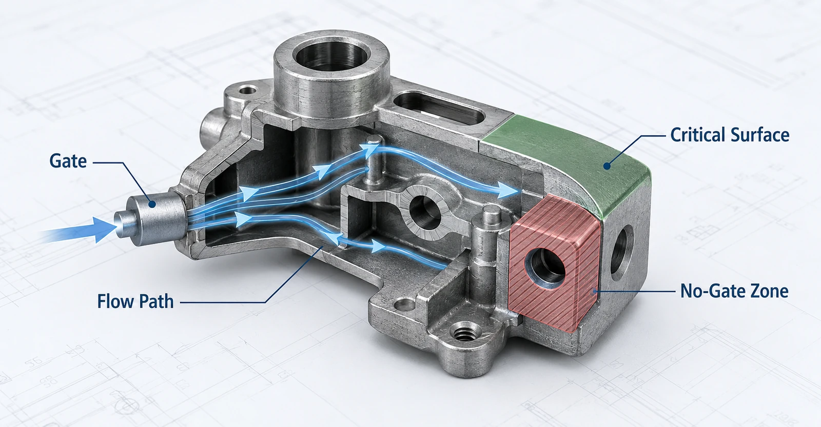
This visual is created to explain gate-design review logic. It is not a customer part, production record, or actual mold-flow simulation.
- Gate design rules at a glance
- Why review gate design before tooling?
- Where should the gate be placed?
- How does gate location affect flow path?
- Which critical surfaces must be protected?
- Which gate types are common in MIM?
- What risks appear in thin-wall and complex parts?
- How does gate design connect with other DFM topics?
- What should be reviewed before tooling?
- What gate design mistakes should be avoided?
- FAQ about MIM gate design
Why Gate Design Must Be Reviewed Before MIM Tooling
Gate design is often treated as a tooling detail, but in MIM it affects part quality, surface restrictions, degating, finishing, and sometimes dimensional stability. Once the mold layout is fixed, changing the gate position may require tool modification, new validation, or design compromise. This is why gate location should be discussed before mold manufacturing begins, especially when the part has cosmetic surfaces, sealing areas, thin walls, holes, slots, or tight inspection requirements.
From a design review perspective, the gate controls three practical questions:
- Can the MIM feedstock fill the cavity predictably? Fine metal powder mixed with binder does not behave exactly like a simple plastic melt. The flow path must account for part thickness, feature interruption, core pins, slots, ribs, and small details.
- Will the gate vestige affect the final part? Gate removal can leave a small mark or require secondary finishing. If this mark appears on a cosmetic surface, sealing surface, sliding surface, or assembly datum, it may become a functional or appearance problem.
- Can the gate be removed without damaging the part? Small MIM parts often include thin ribs, miniature bosses, narrow slots, or fragile features. A gate placed too close to a delicate area can increase degating damage risk.
Engineering note: A common mistake is to choose a gate only because it is easy for the mold. In practice, the gate must also match the part’s function, visible surfaces, dimensional requirements, degating method, and post-processing plan. For broader tooling structure topics, review MIM mold design.
What should be confirmed before tooling?
- Preferred gate side or restricted no-gate surfaces;
- Cosmetic, sealing, sliding, or contact surfaces;
- Critical dimensions and inspection datums;
- Thin-wall regions and long flow paths;
- Small holes, slots, ribs, or core-pin areas;
- Required surface finish after sintering;
- Whether gate vestige can be removed by machining, polishing, or finishing;
- Estimated production volume and degating strategy.
This does not mean the customer must fully design the gate. In most projects, the customer defines functional restrictions, while the MIM manufacturer evaluates manufacturable gate locations, runner access, filling behavior, and degating feasibility.
Where Should the Gate Be Placed on a MIM Part?
The best gate location depends on part geometry, wall thickness, surface requirements, and tooling access. In many MIM designs, the preferred direction is to allow feedstock to flow from a thicker or more stable region toward thinner sections. The EPMA overview of metal injection moulding also explains MIM as a process using powder-binder feedstock, green parts, binder removal, sintering shrinkage, and controlled dimensional change.
However, “place the gate at the thickest area” is not a universal rule. A thick area may also be a sealing face, visible face, datum surface, or precision contact zone. In that case, gate placement must be balanced against function, surface requirements, tooling access, and any secondary operation that may remove the gate vestige.

This decision map is a representative visual aid, not a customer component, approved tooling layout, or actual production result.
Gate Placement and Critical Surface Decision Matrix
| Review Area | Preferred Decision | Risk If Ignored |
|---|---|---|
| Stable or thicker feeding area | Consider when it supports predictable filling and is not functionally restricted. | Short shots, poor filling balance, or local flow instability. |
| Thin wall or long flow path | Review flow length, section transitions, pressure loss, and fill direction. | Incomplete filling, flow marks, or unstable thin-wall replication. |
| Holes, slots, and core pins | Place the gate so flow splitting and meeting points remain away from critical zones where possible. | Weld lines, air traps, or local weakness near interrupted features. |
| Visible cosmetic surface | Usually define as a no-gate zone unless later finishing can reliably remove the vestige. | Visible marks or added finishing cost. |
| Sealing, sliding, or contact surface | Avoid gate placement or review only with a validated removal plan. | Leakage, friction, wear, or contact interference. |
| Assembly or inspection datum | Avoid gate placement and protect the reference surface. | Fit variation, measurement inconsistency, or assembly interference. |
| Hidden or non-functional side face | Often preferred when the area is accessible and safe for degating. | Lower functional risk and easier vestige control. |
| Machined-after-sintering area | Possible when stock removal and access are already included in the process plan. | Added cost, but the vestige may be removed with the planned machining operation. |
How should no-gate zones be marked?
For RFQ and DFM review, the drawing should not only show dimensions. It should also identify visible surfaces where gate vestige is not acceptable, sealing or contact faces, sliding or wear surfaces, inspection datums, areas requiring polishing or coating, and areas where a small gate mark is acceptable.
This information helps the MIM supplier avoid making a tooling decision that later conflicts with the part’s function or appearance. For wall and section-thickness decisions that affect filling behavior, review MIM wall thickness design.
How Gate Location Affects MIM Feedstock Flow Path
MIM feedstock contains fine metal powder and binder. Its flow behavior is affected by wall thickness, feature geometry, mold filling pressure, flow length, and changes in section thickness. Gate location influences how the feedstock front moves through the cavity, where flow fronts meet, and whether certain features are filled predictably.
The selected gate and runner layout must then be verified during the MIM injection molding process, where injection speed, pressure, mold temperature, venting, packing, cooling, and green-part release interact with the planned flow path. A gate location that appears reasonable in the drawing may still need adjustment if trial molding shows short shots, unstable weld-line position, air trapping, excessive shear, or inconsistent cavity filling. When these symptoms appear during trial molding, the MIM injection molding defects guide helps separate parameter-related issues from gate, venting, feedstock, tooling, and geometry causes.
The MIMA Design Center notes that MIM gates must balance manufacturability, function, dimensional control, and appearance. It also discusses gate placement near the parting line, thick-to-thin flow, gate vestige, and balanced filling for multi-cavity tools.

This visual explains representative flow-path risks. It is not an actual mold-flow analysis, trial record, or customer-part simulation.
Flow risks that should be reviewed
| Flow Risk | Typical Cause | Gate Design Review Action |
|---|---|---|
| Short shot | Long, thin, or restricted flow path | Review gate side, wall thickness, fill direction, and feature spacing |
| Weld line | Flow splits around holes, core pins, or slots | Review gate position and where flow fronts meet |
| Flow line | Thin-to-thick flow or unstable filling route | Review gate location and section transitions |
| Air trap | Dead-end pocket or poor venting area | Review flow direction, cavity layout, and venting strategy |
| Local surface defect | High shear or poor filling near gate area | Review gate size, gate type, and surface restriction |
| Unbalanced filling | Asymmetric gate location or multi-cavity imbalance | Review mold layout, runner balance, and cavity-to-cavity consistency |
Why holes, slots, and core pins matter
Holes, slots, and core-pin features can split the flow front. When the separated flow fronts meet again, weld lines or local weakness may appear depending on material, geometry, and molding conditions. This does not mean holes or slots should be avoided in MIM. It means they should be reviewed together with gate position, wall thickness, venting path, and final surface requirements.
For parts with several holes, long slots, deep pockets, or narrow bridges, the gate should be placed so filling remains as predictable as possible. If the gate forces feedstock to travel around multiple interruptions before filling thin areas, the design may need adjustment before tooling. For more feature-specific design review, see holes, slots and undercuts in MIM. For process-quality context, review how injection molding affects MIM part quality and how feedstock affects MIM part quality.
Gate Marks and Critical Surfaces: What Must Be Protected?
A gate mark is not only a cosmetic issue. It can become a functional issue if it is located on a sealing surface, sliding contact, inspection datum, assembly face, or high-tolerance area. In MIM, the gate vestige may be removed, reduced, hidden, or finished depending on gate type, material, geometry, and post-processing. But it should not be assumed that every gate mark can be removed without cost, dimensional impact, or surface risk.
The practical design question is: which surfaces must remain free from visible or functional gate vestige?

This surface map is a representative design-review aid. It is not a customer drawing, inspected component, or production acceptance record.
Which Surfaces Should Be Defined as No-Gate Zones?
Use the combined decision matrix above to define surface restrictions. The highest-priority no-gate zones are sealing faces, sliding or contact surfaces, assembly and inspection datums, and visible cosmetic areas. Hidden recessed faces, non-functional side faces, or surfaces already scheduled for machining may accept a gate only after degating access, stock allowance, finish, and dimensional risk are reviewed.
When can a gate mark be acceptable?
A small gate vestige may be acceptable when it is on a hidden side face, outside the sealing or contact area, away from inspection datums, and not located near a fragile feature that can be damaged during trimming. It may also be acceptable when the surface will be machined, polished, tumbled, or otherwise finished after sintering. The decision should still be documented before tooling because changing a gate after mold fabrication is usually more expensive than marking surface restrictions during RFQ.
Can gate marks be completely removed?
Sometimes they can be reduced or removed through machining, polishing, tumbling, blasting, or other finishing processes. But removal depends on material hardness after sintering or heat treatment, gate size and gate position, local geometry and access, surface finish requirement, whether dimensional stock is available for removal, and production cost.
A safer engineering approach is to define no-gate areas early instead of relying on late-stage finishing to solve a gate placement problem. When gate location may affect a datum or critical dimension, review the related MIM tolerances requirements before tooling.
Which Gate Types Are Commonly Used in MIM Parts?
Gate type selection depends on part geometry, surface restrictions, production volume, and the practical degating method. This section is not a complete mold design manual. Its purpose is to help product engineers understand why a MIM manufacturer may recommend one gate type instead of another and what trade-offs should be discussed during DFM.
| Gate Type | Typical Use | Advantage | Main Risk |
|---|---|---|---|
| Edge / Tab Gate | Accessible side face or thicker region | Stable filling and simpler tooling | Larger gate vestige; trimming may be needed |
| Tunnel / Sub-gate | Hidden or less visible area | Smaller visible mark; possible automatic separation | More tooling complexity and review needed |
| Jump / Drop Gate | Restricted geometry or special access condition | Can solve difficult feeding access | Must review gate vestige and degating risk |
| Direct Gate | Special cases with short flow path | Simple and direct filling route | Higher visible mark or local surface risk |
| Multiple Gates | Larger or complex geometry | Shorter flow length in some layouts | Weld-line location and balance must be reviewed |
How should engineers use this table?
The table is not a substitute for mold-flow review or supplier DFM. It is a practical way to understand trade-offs. If a part has a hidden side face, a sub-gate or tunnel gate may be reviewed. If filling stability is more important than appearance, a tab gate may be acceptable. If a part has a strict cosmetic surface, gate type and gate position must be selected together. If the gate must be removed manually, the surrounding features should be strong enough to avoid damage.
Gate Design Risks in Thin-Wall, Small and Complex MIM Parts
MIM is often selected for small, complex metal parts, but complex geometry makes gate design more important. Thin walls, narrow bridges, undercuts, slots, holes, and micro features can all influence flow path and gate removal. The real risk is not usually one feature by itself. The risk is the combination of gate location, feedstock path, local wall thickness, tooling access, and final surface requirements.
| Problem | Why It Happens | What to Review Before Tooling |
|---|---|---|
| Thin-wall short shot | Flow path is too long or wall is too thin for stable filling | Gate side, wall thickness, material, injection path |
| Weld line near hole | Flow splits around core pin or hole feature | Gate location, hole layout, flow meeting point |
| Gate removal damage | Gate is too close to delicate feature | Degating method, gate access, local feature strength |
| Visible gate mark | Gate placed on cosmetic surface | No-gate zone, hidden surface option, finishing plan |
| Local dimensional variation | Unbalanced flow or poor filling path | Gate symmetry, critical dimension location, mold layout |
| Air trap in pocket | Flow enters a dead-end cavity area | Gate direction, venting path, pocket geometry |
Representative scenario disclosure: The following scenarios are representative engineering examples created to explain common gate-design risks. They are not customer project records or actual production case studies.
Representative Engineering Scenario: Thin-Wall Short Shot Near a Side Slot
What problem occurred: A small MIM component showed incomplete filling near a thin side slot during early molding trials.
Why it happened: The gate forced feedstock through a long, narrow path before reaching the slot area.
What the real system cause was: The issue was not only injection pressure. The gate location, wall thickness transition, and slot position created a high-risk flow path.
How it was corrected: The team reviewed the gate side, adjusted local wall transition geometry, and rechecked the filling path before finalizing tooling changes.
How to prevent recurrence: During DFM, review thin-wall areas, slots, and flow length together instead of treating the gate as a separate tooling decision.
Representative Engineering Scenario: Gate Vestige on an Assembly Face
What problem occurred: A gate mark appeared on a surface later used as an assembly contact face.
Why it happened: The drawing did not identify the face as functionally restricted, so the tooling plan treated it as an acceptable gate area.
What the real system cause was: The problem was a communication gap between product function and tooling design.
How it was corrected: The surface was reclassified as a no-gate zone, and the gate location was reviewed for a less critical side face.
How to prevent recurrence: Mark cosmetic, sealing, datum, and assembly-contact faces clearly in the 2D drawing before RFQ or tooling review.
For broader part geometry review, see MIM part design. For dimensional risk context, review how part dimensions affect final MIM quality.
MIM Gate Design Checklist Before Tooling
Before tooling, the customer and MIM supplier should review gate-related requirements using the drawing and 3D model. This checklist helps avoid late changes after mold manufacturing and reduces the risk of discovering surface restrictions only after first molded samples are produced.

This checklist graphic is a representative review aid. It is not a customer submission, signed approval record, or project-specific DFM report.
Gate Design DFM Review Checklist
| Information to Provide | Why It Matters |
|---|---|
| 2D drawing | Identifies critical dimensions, datums, and restricted surfaces |
| 3D CAD model | Allows review of flow path, hidden features, and mold access |
| Cosmetic surface marking | Helps avoid visible gate vestige |
| Sealing / contact surface marking | Helps protect functional surfaces |
| Assembly datum or inspection datum | Prevents gate placement on measurement or fit references |
| Material requirement | Supports review of feedstock behavior and processing risk |
| Tolerance requirement | Helps protect high-risk dimensions |
| Surface finish requirement | Determines whether gate vestige can be removed or hidden |
| Heat treatment or secondary process | May change hardness, finishing feasibility, or distortion risk |
| Estimated annual volume | Supports gate type, degating method, and tooling strategy |
| Application background | Helps identify surfaces that may not be obvious from geometry alone |
What should be marked on the drawing?
- No-gate surfaces;
- Cosmetic or visible faces;
- Sealing faces;
- Sliding or contact surfaces;
- Datums and inspection references;
- Critical dimensions;
- Surfaces that will be machined after sintering;
- Areas where minor gate vestige is acceptable.
What should be checked after first molding trials?
During trial review, the engineering team should confirm that the gate vestige is located in the approved area, degating does not damage thin features, no-gate surfaces remain protected, short-shot or weld-line risks are not appearing near critical features, and key dimensions are not affected by trimming or finishing. If a gate change is needed after trial, the cause should be linked back to surface restrictions, flow path, tooling access, or missing drawing information rather than treated as an isolated cosmetic issue.
First Trial Review: Gate-Related Acceptance Checks
| Check Item | What to Inspect | Why It Matters |
|---|---|---|
| Gate vestige location | Confirm the gate mark appears only in the approved area. | Prevents unexpected marks on cosmetic, sealing, datum, or contact surfaces. |
| Degating damage | Check nearby ribs, thin walls, small bosses, slots, and fragile features after gate removal. | Small MIM features can be damaged if the gate is too close or trimming access is poor. |
| Weld-line or flow-line risk | Inspect areas where flow fronts meet around holes, slots, or core-pin features. | Helps confirm whether the selected gate location creates visible or functional flow defects. |
| Short-shot sensitive zones | Review thin walls, long flow paths, narrow bridges, and remote pockets. | Confirms whether the feedstock reaches high-risk features consistently during molding. |
| Critical dimensions near gate area | Measure dimensions affected by gate vestige, trimming, local finishing, or datum interference. | Ensures gate removal and surface cleanup do not compromise inspection or assembly requirements. |
For a broader preparation tool, use the MIM DFM design checklist before sending drawings for review.
Common Gate Design Mistakes to Avoid
Placing the gate on a cosmetic surface
A visible gate mark may require extra finishing or may still remain visible after finishing. If the surface is customer-facing or decorative, it should usually be marked as a no-gate area.
Ignoring sealing or contact surfaces
A small gate vestige can become a major issue if it interferes with sealing, sliding, wear behavior, or assembly contact. These surfaces should be identified before tooling.
Feeding from thin sections into thicker areas without review
Thin-to-thick flow can increase filling and surface risk. This is why thick-to-thin flow is commonly preferred where geometry and function allow it.
Ignoring holes, slots, or core pins in the flow path
Features that split flow fronts can create weld-line or air-trap risk. Gate placement should be reviewed together with hole and slot layout.
Choosing a gate only for easy tooling
A gate that is easy to machine into the mold may not be acceptable for the final product. Tooling convenience must be balanced against part function, appearance, and inspection requirements.
Forgetting degating and finishing cost
Gate removal is part of the production plan. If gate trimming requires manual work, special fixtures, or additional finishing, it can affect cost and consistency. For a wider list of design risks, see common MIM design mistakes.
Request a Gate Location and DFM Review Before Tooling
If your MIM part has cosmetic surfaces, sealing faces, thin walls, holes, slots, tight assembly requirements, or surfaces that cannot accept gate marks, request a gate location and DFM review before tooling. Send XTMIM your 2D drawings, 3D CAD files, material requirements, critical tolerances, surface finish requirements, annual volume estimate, and application background.
The engineering team can review gate location, feedstock flow path, gate vestige risk, no-gate zones, degating feasibility, critical surface protection, and related tooling risks before mold manufacturing or production planning.
Submit Your Drawing Request a QuoteFAQ About MIM Gate Design
What is gate design in metal injection molding?
Gate design defines where and how MIM feedstock enters the mold cavity. It affects filling direction, flow path, gate vestige, degating, surface condition, and whether critical surfaces are protected before tooling.
Where should the gate be placed on a MIM part?
The gate is often reviewed near a thicker or more stable feeding area so feedstock can flow into thinner sections, but this must be balanced with cosmetic surfaces, sealing areas, assembly datums, and critical dimensions. Final gate location should be confirmed through project-specific DFM review.
Does gate location affect weld lines in MIM?
Yes. Gate location affects where the MIM feedstock flow front splits and reconnects around holes, slots, core pins, or thin-wall features. If flow fronts meet in a functional or visible area, weld-line risk should be reviewed before tooling.
Can a gate be placed near holes or slots?
It can be possible, but the gate location must be reviewed carefully. Holes, slots, and core-pin features can split the flow path, create air-trap risk, or place weld lines near critical areas. The final decision depends on geometry, wall thickness, function, venting, and degating access.
Can MIM gate marks be completely removed?
Sometimes gate marks can be reduced or removed by machining, polishing, tumbling, blasting, or another finishing step. However, removal depends on material, geometry, gate size, surface requirement, and cost. It is safer to define no-gate areas before tooling.
Should the gate always be placed on the thickest section?
Not always. Thick-to-thin flow is often preferred from a filling perspective, but the thickest section may also be cosmetic, functional, or dimensionally critical. Gate location must balance flow behavior with final part function.
How does gate location affect MIM part quality?
Gate location affects feedstock flow path, weld-line risk, short-shot sensitivity, local surface condition, gate vestige, and degating risk. In some geometries, poor gate location can also contribute to dimensional variation or finishing problems.
Can I specify no-gate areas on my drawing?
Yes. For MIM DFM review, it is recommended to mark cosmetic surfaces, sealing surfaces, contact faces, assembly datums, inspection datums, and any area where gate vestige is not acceptable.
Who decides the final gate location, the customer or the MIM manufacturer?
The customer should define functional restrictions such as no-gate surfaces, cosmetic faces, datums, sealing areas, and critical dimensions. The MIM manufacturer then evaluates the manufacturable gate location based on flow path, tooling access, degating, material behavior, and production requirements.
What information is needed for a MIM gate design review?
Send the 2D drawing, 3D CAD model, material requirement, tolerance requirement, surface finish requirement, application background, estimated annual volume, and any no-gate surface restrictions.
Standards and Technical References Note
MIM gate design is not usually determined by a single universal standard value. It is an engineering review topic that depends on geometry, material, feedstock behavior, mold layout, surface requirements, and production volume.
The EPMA Metal Injection Moulding overview is relevant because it explains MIM feedstock, green part formation, debinding, sintering shrinkage, and process control considerations. The MIMA Design Center is relevant because it discusses gate placement, parting line considerations, gate vestige, thick-to-thin flow, and balanced filling. These references support design judgment, but they should not replace project-specific DFM review.
Material standards and material data sheets can support material specification, mechanical property expectations, and quality agreement during a MIM project, but they do not define a universal gate location for every part. Gate design still needs project-specific tooling and DFM review based on geometry, surfaces, tolerances, feedstock flow, and production requirements.