
MIM precision hinge parts are small, complex metal components used inside compact hinge mechanisms, not complete hinge assemblies. Metal Injection Molding is most useful when a hinge component has compact geometry, multiple holes or slots, curved functional surfaces, integrated positioning features, or repeat production requirements that make CNC machining, stamping, or simple turning inefficient.
Typical candidates include hinge cams, link arms, miniature carriers, locking elements, stop blocks, complex hinge plates, and selected short shaft-related parts with non-round features. The engineering decision is not whether a product “uses a MIM hinge,” but which individual hinge components justify fine metal powder feedstock, injection molding, debinding, sintering shrinkage control, and tooling compensation.
For hinge parts with critical holes, friction surfaces, cosmetic zones, torque-related contact areas, or tight assembly alignment, review MIM suitability, material selection, tolerance strategy, gate location, secondary operation needs, and sintering distortion risk before tooling.
MIM Precision Hinge Parts Showcase
These hinge-related metal parts show the compact geometry, small assembly features, visible surfaces, and functional details commonly considered when evaluating a component for Metal Injection Molding in electronic and portable-device assemblies.
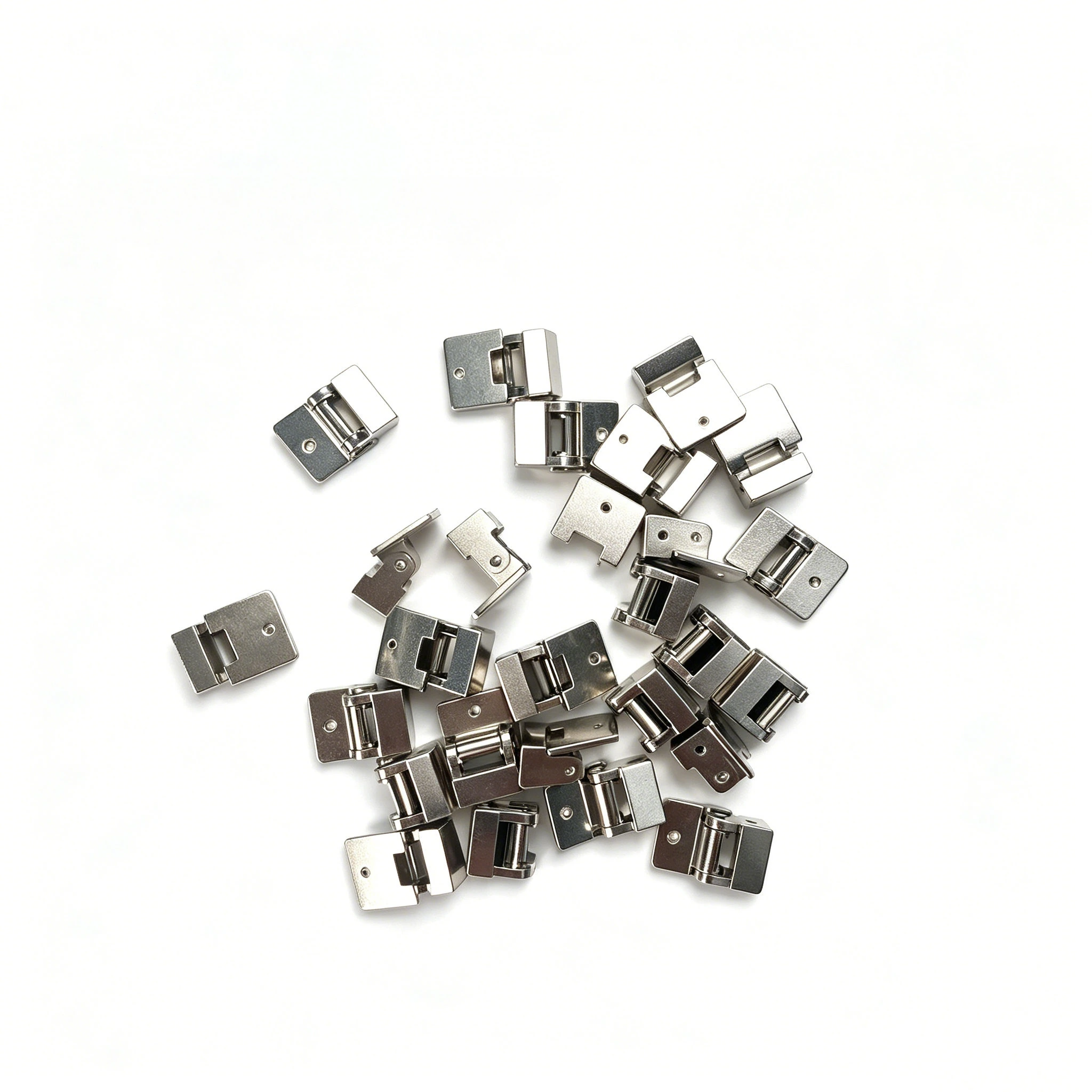
Grouped Precision Hinge Parts
Grouped hinge components make it easier to compare repeatable geometry, small assembly features, and appearance-sensitive surfaces before evaluating suitability, DFM, material, inspection, and RFQ requirements.
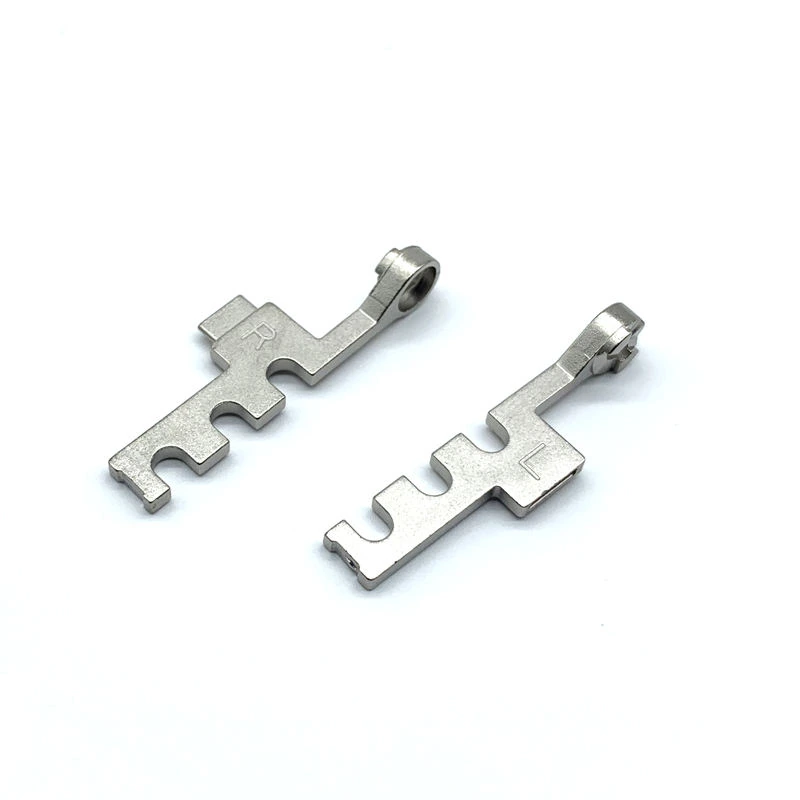
Smartphone Display Hinge Component
Compact display-hinge geometry combines mounting features, visible surfaces, and assembly-fit interfaces that may require early DFM review.
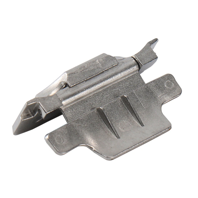
Bluetooth Earphone Box Hinge
Paired compact enclosure-hinge parts place more emphasis on left-right geometry, small-hole position, and assembly alignment.
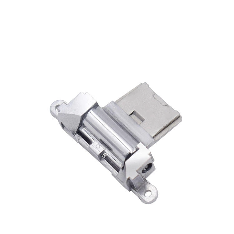
Headphone Hinge Component
Compact portable-device hinge geometry often requires early review of pivot features, surface condition, and assembly fit.
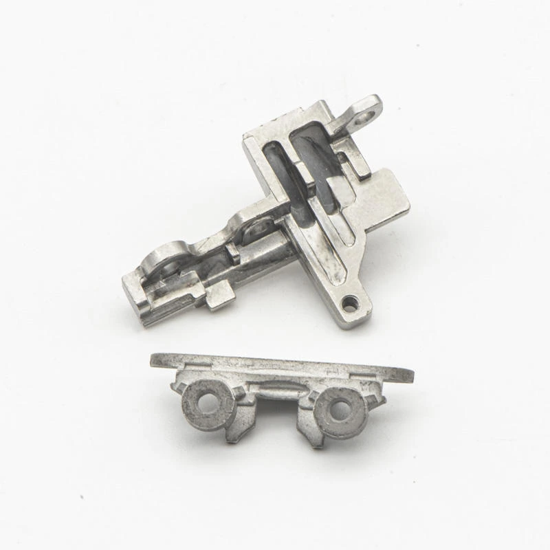
Earphone Box Hinge Detail Parts
Local holes, compact geometry, and small assembly features illustrate the areas most likely to affect molding, sintering, and final fit.
MIM-Relevant Features in Precision Hinge Parts
These examples show compact geometry, small holes, curved or visible surfaces, and assembly-oriented features that may justify a MIM manufacturability review.
Scope of MIM Hinge Component Evaluation
MIM evaluation applies to individual precision hinge components rather than complete hinge assemblies, repair hinges, standard hardware hinges, or finished hinge modules.
Next Review Steps Before Tooling
After confirming the part family, engineers should review MIM suitability, gate location, wall thickness, critical holes, material choice, surface requirements, inspection datums, and RFQ inputs.
MIM Precision Hinge Part Suitability Matrix
The first decision is whether the part geometry actually benefits from MIM. A hinge part is not a good MIM candidate simply because it is small or precise. MIM becomes valuable when complexity, material performance, production volume, and functional integration justify tooling, shrinkage compensation, debinding and sintering development, and inspection planning.
| Hinge Part Type | MIM Suitability | Why MIM May Fit | Key Review Point |
|---|---|---|---|
| Hinge cams / torque cams | High | Compact curved profile, local contact surfaces, repeatable geometry | Wear surface, gate location, shrinkage distortion |
| Link arms / rotating arms | Medium–High | Small load-bearing geometry with holes and compact features | Flatness, hole deformation, sintering support |
| Hinge plates with holes, slots, or bosses | Medium–High | Integrated holes, slots, bosses, and positioning features | Plate distortion, hole tolerance, datum strategy |
| Miniature hinge carriers | High | Multiple assembly features integrated into one compact component | Wall thickness, mold release direction, functional surfaces |
| Locking / positioning elements | High | Small, complex, repeatable engagement features | Contact surface strength, edge condition, burr control |
| Short feature-rich pins / shaft-related parts | Conditional | Useful only when flats, grooves, shoulders, or non-round features exist | Do not replace simple turned pins without a cost or design reason |
| Simple flat plates | Low | Usually better suited to stamping or machining | Cost boundary and production route check |
| Long straight shafts or pins | Low | Usually better suited to turning, cold forming, or grinding | Straightness, roundness, cost, and process fit |
What Are MIM Precision Hinge Parts?
MIM precision hinge parts are metal components inside compact hinge mechanisms that require small size, complex shape, mechanical strength, dimensional repeatability, and reliable assembly fit. They may be used in foldable devices, laptops, wearable devices, wireless earbud cases, portable electronics, compact camera mechanisms, robotics joints, compact industrial devices, and other small rotating assemblies.
They are not the same as complete hinge modules. In practice, a hinge assembly may combine MIM parts with stamped parts, machined pins, turned shafts, screws, springs, washers, die-cast parts, plastic parts, or other precision components. MIM should be evaluated part by part, because different components in the same hinge may belong to different manufacturing routes.
From a design review perspective, a MIM hinge part usually has at least one of the following characteristics: complex three-dimensional geometry, small holes or slots, compact load-bearing structure, curved cam or contact surfaces, integrated positioning features, or surfaces that affect torque, wear, rotation, or assembly alignment.
A common mistake is to call the entire mechanism a “MIM hinge.” For RFQ and DFM review, the more useful question is which component should be molded, which should be machined, and which should remain stamped or turned.
When Is MIM Suitable for Precision Hinge Components?
MIM should be considered when the hinge component is small, geometrically complex, and expected to move into medium- to high-volume production after design validation. The process is less attractive for simple, low-volume, or large parts where conventional machining, stamping, die casting, or turning can produce the part more economically.
Small Complex Geometry
MIM can form compact profiles, curved surfaces, holes, bosses, ribs, and integrated features without machining every surface separately.
Stable Production Design
MIM becomes more practical after the hinge geometry is validated and the project is moving toward repeat production.
Functional Integration
The strongest candidates reduce machining steps, reduce assembly parts, or improve repeatable geometry in a compact mechanism.
Before tooling, the key question is whether the complexity has real manufacturing value. Useful complexity may reduce CNC operations, combine multiple functions into one molded component, improve batch-to-batch repeatability, or enable a compact geometry that is difficult to stamp or turn. Complexity that only adds tooling slides, tight features, or cosmetic risk without reducing cost or assembly burden may not justify MIM.
When MIM Is Not the Best Choice for Hinge Parts
MIM is not a universal replacement for CNC machining, stamping, die casting, or turning. A reliable MIM review should also identify parts that should remain outside the MIM route.
- Large simple hinge plates that can be stamped with better cost efficiency.
- Long straight pins or shafts that can be turned, cold formed, or ground with better straightness control.
- Simple flat brackets with no integrated geometry or functional surface advantage.
- Low-volume prototypes where CNC machining is faster and more flexible during design changes.
- Large cosmetic hinge covers where surface appearance, distortion, and finishing risk may dominate the decision.
- General hardware hinges used in furniture, doors, or simple mechanical enclosures.
- Parts with frequent design changes before the geometry, datum scheme, and critical surfaces are frozen.
This boundary matters because MIM requires tooling investment, shrinkage compensation, debinding and sintering control, and dimensional validation. When the part is simple, the additional process route may add cost without improving function.
Common MIM Parts Used in Precision Hinge Mechanisms
Final feasibility depends on drawing geometry, material, critical dimensions, cosmetic requirements, production volume, and assembly function. The part name alone is not enough for a reliable MIM decision.
Hinge Cams / Torque Cams
Hinge cams and torque-related cam parts are strong MIM candidates when they include compact curved profiles, positioning features, local contact zones, and repeated production requirements. The key review points are cam surface definition, wear zone, gate vestige position, sintering distortion risk, surface finish, and whether any post-sintering sizing or machining is needed for the functional profile.
Link Arms / Rotating Arms
Small link arms may be suitable when they include compact load-bearing geometry, multiple holes, bosses, ribs, or non-flat features. Long and slender arms require careful review because thin sections may be sensitive to green part handling, debinding support, sintering distortion, and hole alignment shift.
Hinge Plates with Holes and Slots
A simple flat plate is usually not a strong MIM candidate. A hinge plate becomes more suitable when it includes holes, slots, bosses, local thickness changes, molded-in positioning features, or multi-plane geometry. The engineering review should focus on flatness, hole location, wall balance, and datum selection.
Miniature Hinge Carriers
Miniature carriers are strong candidates when they combine walls, ribs, pockets, holes, bosses, and location features into one compact part. The DFM review should cover minimum wall thickness, mold release direction, feedstock flow path, debinding support, sintering support, and inspection access.
Locking / Positioning Elements
Locking blocks, detent parts, and positioning elements often affect the feel, position, or mechanical stability of the hinge. Contact surface condition, edge quality, local strength, and material choice should be reviewed before tooling. A small burr, flash, or gate mark on the wrong surface can affect movement or assembly feel.
Short Feature-Rich Pins / Shaft-Related Parts
Short hinge pins may be reviewed for MIM only when they include flats, grooves, shoulders, locking features, or non-round geometry. Simple long cylindrical pins are usually better suited for turning, cold forming, or grinding. For deeper shaft-related guidance, see MIM shafts and pins.
Where MIM Precision Hinge Parts Are Used
MIM precision hinge parts are most relevant in compact products where the hinge must combine mechanical movement, strength, space efficiency, and repeatable assembly. Device applications help show where MIM hinge components are commonly used, but manufacturing suitability still needs to be evaluated at the individual-part level because a complete hinge assembly may combine MIM, machining, stamping, turning, springs, fasteners, and other processes.
Foldable Phone Hinge Parts
Foldable phone hinges may include compact mechanical components with small features, curved surfaces, load-bearing areas, and alignment requirements. MIM may be considered for selected cams, carriers, link elements, positioning parts, or miniature structural components.
Laptop Hinge Parts
Laptop hinge mechanisms may use selected small metal components that require strength, compact geometry, or stable assembly fit. MIM becomes more relevant when the part includes complex geometry, multi-feature integration, or high-volume consistency requirements. This guidance applies to custom-manufactured precision hinge components, not replacement or repair hinges for finished laptops.
Wearable Device Hinge Parts
Wearable devices may use small hinge or rotating components where compact size, corrosion resistance, surface condition, and user comfort matter. Related content: MIM wearable device parts.
Earbud and Charging Case Hinge Parts
Small hinges in earbuds, charging cases, or compact consumer electronics may include miniature brackets, stops, locking details, or rotating elements. MIM can be evaluated when geometry, strength, and volume justify the process, but many simple parts may remain better suited to stamping or machining.
MIM vs CNC, Stamping, Die Casting, and Turning for Hinge Parts
The best process depends on part geometry, production volume, tolerance requirements, surface requirements, and whether the design is stable. A practical review should start with the hinge drawing, not with a generic process preference.
| Process | Best Fit for Hinge Components | Weak Fit |
|---|---|---|
| MIM | Small, complex metal parts with integrated features, stable geometry, and higher production volume | Large simple parts, unstable designs, low-volume simple parts |
| CNC machining | Prototypes, low-volume parts, tight local features, frequent design changes | High-volume complex small parts with many machined features |
| Stamping | Flat plates, thin sheet parts, simple brackets, high-volume sheet metal parts | Complex 3D geometry, thick compact parts, curved functional surfaces |
| Die casting | Larger structural parts, housings, some compact metal shapes | Very small high-strength precision features or thin detailed components |
| Turning / cold forming | Pins, shafts, bushings, simple round parts | Non-round complex features, integrated multi-surface geometry |
For part geometry, shrinkage, wall thickness, and tolerance strategy, see DFM for MIM. If a hinge component includes compact gear-sector or synchronization features, evaluate those features separately using the criteria in MIM micro gears.
DFM Risks for MIM Precision Hinge Parts
MIM hinge parts should be reviewed before tooling because small geometry changes can affect injection molding, green part handling, debinding, sintering shrinkage, and final assembly fit. The real issue is not only whether the part can be molded, but whether the functional surfaces remain stable after shrinkage and finishing.
| DFM Risk | Why It Matters for Hinge Parts | Review Before Tooling |
|---|---|---|
| Gate vestige on contact or cosmetic surfaces | Can affect rotation, wear, appearance, or assembly | Define no-gate surfaces early |
| Sintering distortion in thin arms or plates | Can affect flatness, hole position, and assembly alignment | Review wall transitions, support strategy, and datum scheme |
| Hole deformation | Can affect pivot fit, pin fit, screw assembly, or rotational clearance | Confirm hole size, location, tolerance, and post-processing needs |
| Contact surface wear | Can affect torque, movement feel, or service life | Review material, heat treatment, finishing, and surface condition |
| Critical surface ambiguity | Supplier and customer may optimize different surfaces | Mark functional, cosmetic, assembly, and non-critical surfaces clearly |
Representative Engineering Scenario: Gate Vestige on a Contact Surface
A compact MIM hinge cam met its dimensional requirements, but assembled units showed inconsistent rotational feel. The issue was traced to a small gate vestige located on a functional cam-contact surface. The drawing controlled the part geometry, but it did not identify that contact area as a no-gate or no-parting-line surface.
The corrective action was to move the gate away from the contact surface, clearly identify the critical functional area, and include gate-vestige inspection on the cam profile.
For similar hinge parts, DFM should distinguish functional, cosmetic, assembly, and non-critical surfaces before tooling. Gate location, parting-line position, and surface-finish requirements can then be reviewed against the actual function of each surface.
Material and Surface Review for MIM Hinge Parts
Material selection for MIM hinge parts should be based on load, contact behavior, corrosion environment, surface appearance, finishing requirements, and heat treatment compatibility. Hinge components may experience repeated contact, rotation, friction, handling, and exposure to sweat or humidity, so material and surface treatment need to match the actual service condition.
| Typical Hinge Feature | Requirement | Review Direction | Why It Matters |
|---|---|---|---|
| Load-bearing link arm or carrier | Strength and load resistance | Stainless steel, precipitation-hardening stainless steel, or low-alloy steel review | Supports compact load-bearing structures while keeping deformation and assembly fit under control |
| Wearable or handheld hinge component | Corrosion resistance | Stainless steel or surface protection review | Important for sweat exposure, humidity, repeated handling, and visible device interfaces |
| Cam, stop block, or positioning element | Wear/contact performance | Material hardness, heat treatment, finishing, or coating review | Important for repeated contact, hinge feel, torque consistency, and local surface damage risk |
| Visible hinge plate or exposed component | Cosmetic surface | Polishing, blasting, plating, coating, or controlled visible surface review | Important when gate vestige, parting line, polishing direction, or coating defects may be visible after assembly |
For broader material selection, see MIM materials. For performance-specific requirements, see wear-resistant MIM parts and corrosion-resistant MIM parts.
Inspection Points for Precision Hinge Components
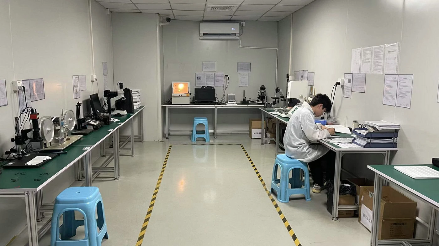
Inspection planning should reflect how the part functions in the hinge mechanism. A complete inspection plan is not only about measuring all dimensions. It should separate critical dimensions, assembly dimensions, contact surfaces, cosmetic surfaces, and process-sensitive features.
Before tooling, the customer and supplier should define CTQ features instead of treating every dimension as equally important. For hinge components, common CTQ items include pivot hole position, datum surfaces, contact surfaces, torque-related cam profiles, visible cosmetic zones, and any surfaces that may require secondary machining or finishing after sintering.
| Inspection Point | CTQ Level | Why It Matters |
|---|---|---|
| Critical hole diameter and position | High | Affects pin fit, rotation, assembly clearance, and alignment |
| Flatness | Medium–High | Affects mating, gap control, and smooth movement |
| Contact surface condition | High | Affects wear, torque feel, and repeatability |
| Gate vestige and parting line | Medium–High | Can affect cosmetic zones, friction surfaces, or assembly faces |
| Burr / flash / edge condition | Medium | Can interfere with assembly, tactile feel, or movement |
| Dimensional consistency | High | Affects batch assembly and production stability |
Representative Engineering Scenario: Hole Alignment Drift After Sintering
A compact hinge link met the specified hole diameter, but assembly alignment varied after sintering. The problem was not the hole size itself. Uneven wall sections and a thin arm around the pivot hole made the feature more sensitive to sintering distortion and support conditions.
The drawing controlled hole diameter but did not clearly define its relationship to the mating surface, part flatness, or the functional datum used during assembly.
The correction was to define the functional datum structure, add hole-position and flatness controls where required, and review the sintering support and inspection method together. For similar hinge parts, DFM should evaluate hole position, datum relationships, wall balance, sintering support, and final assembly condition as one system rather than treating each dimension independently.
RFQ Checklist for MIM Precision Hinge Parts
A useful RFQ for MIM hinge parts should provide enough information for manufacturability, tooling, material, tolerance, surface, and production review. A drawing alone may not be sufficient if the part has hidden assembly, torque, wear, or motion requirements.
| RFQ Input | Why It Is Needed |
|---|---|
| 2D drawing | Defines dimensions, tolerances, surface notes, datums, and critical features |
| 3D CAD file | Helps review geometry, tooling direction, wall transitions, shrinkage risk, and moldability |
| Material requirement | Supports strength, corrosion, wear, heat treatment, or magnetic review |
| Tolerance notes | Helps evaluate whether as-sintered tolerance is enough or secondary operations are needed |
| Surface finish requirement | Defines cosmetic, friction, coating, or assembly surfaces |
| Assembly position | Shows which surfaces are functional, visible, contact-related, or non-critical |
| Annual volume | Helps determine whether MIM tooling economics are reasonable |
| Load / torque / cycle requirement | Helps evaluate material, contact surface, wear, and functional risk |
How to Prepare a Custom Hinge Part for MIM Review
For a custom hinge project, start by identifying the actual MIM candidate, marking functional and cosmetic surfaces, and confirming which surrounding components should remain machined, stamped, turned, or produced by other processes.
Identify the MIM Candidate
Separate the MIM candidate from the complete hinge assembly. Identify whether the part is a cam, carrier, link arm, locking element, stop block, bracket, plate, or short feature-rich shaft-related component.
Mark Functional and Cosmetic Surfaces
Clearly mark contact surfaces, visible areas, assembly datums, holes, slots, torque-related surfaces, and any surfaces where gate vestige, parting line, burr, or polishing direction may affect function or appearance.
Confirm the Process Boundary
Do not force every hinge-related part into MIM. Simple flat plates, long straight pins, and early low-volume prototype parts may still be better suited for stamping, turning, machining, or other manufacturing routes.
Submit Your Hinge Part Drawing for MIM Review
Contact XTMIM when your component is small, complex, metal, and difficult to produce efficiently by CNC machining, stamping, die casting, or turning. Please provide the 2D drawing, 3D CAD file, material requirement, tolerance notes, surface finish requirement, estimated annual volume, assembly position, and any load, torque, wear, or cycle requirements.
XTMIM’s engineering review can help evaluate MIM suitability, tooling direction, gate location, debinding and sintering risk, material choice, surface requirements, secondary operation needs, and inspection strategy before tooling, trial production, or mass production planning.
FAQ About MIM Precision Hinge Parts
Are complete hinge assemblies made by MIM?
Usually, no. MIM is more commonly used for selected small metal components inside a hinge assembly, such as cams, carriers, link arms, locking elements, stop blocks, or complex brackets. A complete hinge module may also include stamped parts, machined pins, screws, springs, washers, shafts, plastic parts, or die-cast components.
Which hinge parts are best suited for Metal Injection Molding?
The strongest MIM candidates are small, complex metal parts with integrated features, compact load-bearing geometry, multiple holes or slots, curved contact surfaces, or repeatable positioning features. Examples include hinge cams, miniature carriers, locking elements, stop blocks, complex hinge plates, small brackets, and selected short shaft-related parts with non-round features.
When is CNC machining better than MIM for hinge parts?
CNC machining is often better for low-volume prototypes, early development parts, frequent design changes, or simple geometries that do not justify MIM tooling. CNC may also be needed for very tight local features or post-sintering secondary operations.
Can MIM be used for foldable phone hinge parts?
MIM can be used for selected foldable phone hinge components, especially small parts with complex geometry, compact load paths, curved surfaces, and high-volume repeatability requirements. However, the complete hinge mechanism is not normally a single MIM part.
What information is needed to quote MIM hinge parts?
A useful RFQ should include 2D drawings, 3D CAD files, material requirements, tolerance notes, surface finish requirements, annual volume, assembly position, and any load, torque, wear, or cycle requirements.
What are common DFM risks in MIM hinge parts?
Common risks include gate vestige on contact or cosmetic surfaces, sintering distortion in thin arms or plates, hole deformation around pivot features, burr or flash near assembly edges, contact surface wear, unclear functional surfaces, and unrealistic tolerance expectations.
Are long hinge pins good candidates for MIM?
Simple long cylindrical pins are usually not strong MIM candidates. Turning, cold forming, or grinding is often more suitable. MIM may be considered only when a short pin or shaft-related part includes non-round geometry, flats, grooves, shoulders, locking details, or integrated functional features.
XTMIM Engineering Review Scope
XTMIM reviews precision hinge components against MIM process suitability, part geometry, material selection, tooling risk, green-part handling, debinding, sintering shrinkage, dimensional control, surface requirements, production feasibility, and inspection planning.
For precision hinge parts, XTMIM recommends drawing-based review before tooling because hinge components often include critical holes, contact surfaces, cosmetic zones, thin sections, and assembly relationships that cannot be judged from part name alone.
Technical References for MIM Hinge Evaluation
General MIM suitability depends on design, material, process capability, production volume, and component cost rather than part name alone. MIMA Designing with MIM covers candidate selection around material performance, shape complexity, production quantity, and cost, while the MPIF standards resources provide MIM material standards, explanatory notes, and definitions.
The EPMA MIM process overview is relevant for the basic MIM route, including powder and binder feedstock, molding, debinding, and sintering. For material specifications, ASTM B883-24 covers specified Metal Injection Molded materials, while ISO 22068:2012 specifies chemical, mechanical, and physical requirements for sintered MIM materials.
These references support general engineering review, but they do not replace project-specific drawings, material data sheets, agreed inspection plans, or customer acceptance criteria. For precision hinge parts, final acceptance should be based on the customer drawing, 3D CAD model, material requirement, critical dimensions, functional surface definitions, cosmetic requirements, assembly conditions, production volume, and supplier process capability.