MIM Process Selection Insights Which CNC Features Should Stay Machined When Converting a Part to MIM? A feature-level review helps decide which areas can be molded, which may be sized, and which should remain machined after metal injection molding conversion. ``` Quick Answer When converting a CNC-machined part to metal injection molding, not every CNC …
MIM Process Selection Insights
Which CNC Features Should Stay Machined When Converting a Part to MIM?
A feature-level review helps decide which areas can be molded, which may be sized, and which should remain machined after metal injection molding conversion.
```Quick Answer
When converting a CNC-machined part to metal injection molding, not every CNC feature should automatically become an as-molded MIM feature. MIM can form complex near-net-shape geometry, but threads, precision bores, datum faces, sealing lands, bearing seats, sliding contact areas, and inspection references often still need machining, sizing, or special review after sintering.
The correct decision depends on feature function: what controls fit, sealing, alignment, motion, or inspection. For engineers comparing MIM vs CNC machining, the practical question behind CNC features after MIM is not whether the entire part should be “MIM” or “CNC,” but which individual features must remain controlled after MIM.
- Threads
- Precision bores
- Datum faces
- Sealing surfaces
- Bearing seats
- Sliding surfaces

Core conclusion: CNC-to-MIM conversion should be reviewed by feature function, not only by overall part shape.
Which CNC Features Should Stay Machined After a MIM Conversion?
The CNC features most likely to stay machined are the features that control function, assembly, inspection, or surface contact. These features are not always difficult to mold in shape, but they may be difficult to hold in final size, surface condition, or positional relationship after debinding and sintering.
A practical review starts by separating the part into two groups: the overall geometry that benefits from MIM, and the local functional features that may need secondary control. This prevents both over-machining and over-reliance on as-sintered features.
This article does not list every possible MIM secondary operation. It focuses only on CNC-derived features that need a route decision before MIM tooling.
1. Identify function
Does the feature control fit, sealing, motion, inspection, or assembly?
2. Review tolerance
Is the final requirement tighter than a normal as-sintered feature should carry?
3. Check datum logic
Will this surface locate the part during assembly or inspection?
4. Select route
Classify the feature as molded, sized, machined, or review required.
Usually Review for Machining
- Functional threads and tapped holes
- Precision bores and shaft fits
- Sealing lands and contact surfaces
- Datum pads used for inspection or assembly
May Be Molded
- Non-critical outer profiles
- Lightening pockets and reliefs
- Clearance features with wider tolerance
- Geometry that does not control fit or sealing
Review Case by Case
- Local flatness requirements
- Interrupted holes or deep bores
- Features near thick-to-thin transitions
- Surfaces affected by post-processing

Core conclusion: The features most likely to stay machined are the features that control fit, sealing, datum location, or inspection repeatability.
Why Some CNC Features Cannot Simply Become As-Molded MIM Features
MIM is a near-net-shape process, not a guarantee that every CNC tolerance or surface condition can be copied directly into an as-sintered part. During MIM production, feedstock is injection molded, binder is removed, and the part shrinks during sintering. Tooling compensation accounts for expected shrinkage, but local feature behavior can still vary with geometry, wall thickness, support, material, and sintering conditions.
For non-critical geometry, this may be acceptable. For a functional bore, sealing surface, or datum face, small variation may affect assembly or inspection. That is why CNC-to-MIM conversion should review the part feature by feature instead of only comparing the two processes at a general level.
```Sintering Shrinkage and Local Tolerance Risk
Sintering shrinkage is part of the MIM process. Tool design compensates for expected shrinkage, but final part dimensions still need to be reviewed against the function of each feature. A clearance pocket or external contour may be acceptable as molded, while a coaxial bore or tight-fit seat may need machining after sintering.
Surface Function Versus Part Geometry
A surface can be easy to mold geometrically but still unsuitable as a final functional surface. A sealing land may need flatness and surface finish control. A sliding surface may need a specific contact pattern. A bearing seat may need a final diameter and surface condition that cannot be decided only from the molded geometry.
Datum Control and Inspection Repeatability
Datum surfaces deserve special attention. If a surface is used to locate the part during assembly or inspection, its final condition affects how other dimensions are measured. A molded surface may be acceptable for a non-critical reference, but a primary datum face may need machining, sizing, or a clear inspection plan.
Technical Basis for Keeping Selected Features Machined
Industry guidance on MIM secondary operations explains that when tighter tolerances are required for a certain feature, secondary operations can be used, and common machining operations can be applied to MIM components for threads, grooves, undercuts, or other special features that are difficult or expensive to accommodate in tooling.
In this article, that principle is applied at the drawing level. CNC features after MIM should be reviewed by function, tolerance, surface condition, and datum role. This does not mean every MIM part needs machining, and it does not replace a full secondary machining guide.
Engineering rule: A feature should stay machined when the cost of losing function is higher than the cost of the secondary operation. This usually applies to features that control alignment, sealing, load transfer, sliding contact, or repeatable inspection.
Common CNC Features That Usually Require Machining After MIM
The following categories should not be treated as automatic rules, but they are common review triggers. If a CNC feature falls into one of these categories, it should be marked clearly on the drawing and reviewed before tooling.
```Threads and Tapped Holes
Threads are one of the most common features that require special review. Some thread forms may be molded or formed depending on size, material, load, and production requirements, but tapped threads are often safer when the thread controls strength, assembly torque, repeated fastening, or positional accuracy.
- Thread size and depth
- Internal or external thread
- Assembly torque requirement
- Thread engagement length
- Whether the thread is load-bearing
- Whether a molded pilot hole, tapping allowance, or insert strategy is needed
Precision Bores and Reamed Holes
Precision bores, shaft holes, alignment holes, and bearing-related holes often need post-sintering control. A clearance hole may be molded directly, but a bore that controls fit, rotation, concentricity, or alignment may require reaming, machining, or sizing.
Datum Faces and Locating Surfaces
Datum faces and locating surfaces are often more important than their size suggests. A small flat pad may control how the part sits in a fixture or how a mating part is assembled. If this surface is unstable, rough, distorted, or not repeatable, downstream inspection and assembly can become inconsistent.
Sealing Faces and Gasket Contact Surfaces
Sealing surfaces should be reviewed carefully because their function depends on more than nominal geometry. Flatness, surface finish, contact width, and local defects can affect sealing performance. A MIM part may form the sealing geometry, but the final sealing land may still require machining, lapping, polishing, or special inspection depending on the application.
Bearing Seats, Shaft Fits, and Sliding Surfaces
Bearing seats, shaft fits, and sliding contact surfaces often require tighter dimensional and surface control than surrounding geometry. These machined features after MIM may need post-sintering machining, especially when they control rotation, sliding friction, wear behavior, press fit, or concentricity.
| Feature | Why It Needs Review | What Can Go Wrong | Review Before Tooling |
|---|---|---|---|
| Threaded hole | Controls fastening, serviceability, and assembly torque | Weak engagement, cross-threading, or late tapping change | Confirm thread size, pilot condition, engagement depth, and machining route |
| Precision bore | Controls shaft fit, alignment, or rotation | Poor fit, roundness issue, or inspection dispute | Confirm whether molded, sized, reamed, or machined route is required |
| Datum face | Controls measurement and assembly reference | Unstable fixture location or inconsistent inspection data | Confirm datum function and whether the surface must be machined |
| Sealing land | Controls contact width, flatness, and surface condition | Leakage, poor contact, or extra finishing requirement | Mark sealing area and confirm finish or flatness requirement |
| Bearing or sliding surface | Controls wear, fit, motion, or friction behavior | Premature wear, assembly resistance, or poor rotation | Confirm surface condition, fit, and inspection method |
Features That May Be Molded, Sized, or Reviewed Case by Case
Not every CNC feature should remain machined. Keeping too many CNC operations can reduce the cost advantage of MIM and create unnecessary production steps. A good conversion review should also identify which features can be molded directly or corrected through selected MIM sizing.
```Non-Critical External Profiles
External profiles, curved surfaces, weight-reduction pockets, non-functional contours, and complex shapes are often good candidates for MIM. These features are usually part of the reason the project is being considered for MIM in the first place.
Clearance Holes and Non-Functional Recesses
Clearance holes may be molded if the tolerance, roundness, and surface condition are not function-critical. Non-functional recesses, lightening pockets, and relief features may also be molded directly when they do not control mating parts.
Molded Bosses, Ribs, and Weight-Reduction Features
Bosses, ribs, small walls, and complex internal geometry may be good MIM candidates when the design is suitable for injection molding, debinding, and sintering. These features should be reviewed for wall thickness, gate location, sintering support, and distortion risk.
Sizing for Selected Dimensional Control
Sizing can be useful for selected features where the goal is to improve dimensional consistency without fully machining the feature. It is not a universal replacement for CNC machining, but it can be appropriate for some local dimensional controls.
Do Not Over-Machine
If a feature does not control fit, sealing, movement, datum location, or inspection repeatability, keeping it as a CNC operation may add cost without improving function. This is especially true for relief pockets, non-critical contours, and cosmetic geometry that can be molded reliably.
Do Not Under-Control
If a feature controls a mating component, a sliding surface, or a sealing interface, treating it as a normal molded surface can move risk into assembly or inspection. These features should be reviewed before tooling, not after the first samples are measured.
Feature-Level Decision Matrix for MIM, Sizing, and CNC Machining
A feature-level matrix helps prevent the conversion review from becoming too general. Instead of asking whether the whole part should be MIM or CNC, the team reviews each important feature and assigns a likely manufacturing route.
For CNC features after MIM, use the table as a first screening tool. The final route should still be confirmed using the drawing, material, annual volume, critical dimensions, surface requirements, datum structure, and inspection method.
| Feature Type | Functional Role | Usually Molded? | Sizing Possible? | Machining Likely? | Drawing Note to Confirm |
|---|---|---|---|---|---|
| Non-critical external profile | Shape, weight, appearance | Yes | Sometimes | Rarely | Identify only critical profile dimensions |
| Clearance hole | Assembly clearance | Often | Sometimes | Case by case | Confirm clearance requirement and tolerance |
| Precision bore | Alignment, shaft, bearing fit | Sometimes | Sometimes | Often | Confirm diameter, roundness, datum, inspection method |
| Internal thread | Fastening, load, serviceability | Case by case | Rarely | Often | Confirm thread size, depth, torque, engagement |
| Datum face | Locating or inspection reference | Sometimes | Sometimes | Often | Confirm datum function and flatness requirement |
| Sealing face | Leak control or gasket contact | Sometimes | Rarely | Often | Confirm surface finish, flatness, sealing area |
| Bearing seat | Fit, rotation, wear | Sometimes | Sometimes | Often | Confirm fit, surface requirement, concentricity |
| Sliding surface | Friction, wear, motion | Sometimes | Sometimes | Often | Confirm wear requirement and final surface condition |
This matrix is a screening tool, not a tolerance guarantee. Final decisions should be confirmed using the 2D drawing, 3D model, material, annual volume, function notes, and inspection requirements. For projects where tolerance stack-up or sintering variation is already a concern, the tolerance and shrinkage checklist can help organize the drawing review before quotation.

Core conclusion: The best CNC-to-MIM conversion route often combines molded geometry with selected sizing or CNC machining.
What to Mark on the Drawing Before MIM Tooling Review
A CNC-to-MIM review becomes much more accurate when the drawing separates general geometry from critical functional features. If the drawing does not identify which surfaces control function, the supplier may quote the part based only on shape and tolerance blocks. This is why a MIM design review before tooling should confirm machined, sized, and as-molded features before the tool route is locked.
```Critical Dimensions and Tolerance Notes
Identify dimensions that control assembly, fit, alignment, sealing, or movement. Avoid relying only on a general tolerance block when some features are more critical than others. If a dimension is important because it controls a mating part, add a function note.
Machining Allowance and Stock Condition
If a feature is expected to be machined after sintering, the drawing or RFQ package should indicate that the feature requires machining review. The supplier may need to plan machining allowance, fixture strategy, and inspection sequence.
Inspection Datum and Measurement Method
Inspection requirements should be connected to functional datums. If a feature will be measured from a surface that may remain as sintered, the team should confirm whether that datum is stable enough. If the datum itself needs machining, this should be decided before tooling.
Surface Finish and Contact Function Notes
Surface finish should not be added only as a generic requirement. Mark the surfaces where finish matters because of sealing, sliding, wear, cosmetic appearance, or assembly contact.

Core conclusion: Clear drawing notes help avoid late machining changes, inspection disputes, and tooling corrections.
Drawing Review Checklist for CNC Features After MIM
Before sending a CNC part for MIM conversion review, prepare information that separates general molded geometry from local functional surfaces. This helps the engineering team decide which features can be molded, sized, machined, or reviewed case by case.
| Review Item | Why It Matters | What to Provide |
|---|---|---|
| 2D drawing | Defines tolerances, datums, threads, surface finish, and critical dimensions | Latest controlled drawing |
| 3D model | Shows full geometry for moldability and tooling review | STEP or similar neutral file |
| Critical feature list | Separates functional features from general geometry | Marked holes, threads, faces, fits, sealing areas |
| Datum structure | Controls inspection and assembly logic | Datum symbols and explanation if needed |
| Thread requirements | Affects tapping, molded pilot holes, and secondary operations | Thread size, depth, engagement, torque if known |
| Precision holes or bores | Affects reaming, sizing, or machining review | Diameter, depth, function, mating part |
| Sealing or sliding surfaces | Affects machining, lapping, polishing, or inspection | Surface finish, flatness, contact area |
| Material requirement | Affects MIM material availability and final process route | Current CNC material and acceptable alternatives |
| Annual volume | Affects tooling justification and cost review | Estimated annual demand or production range |
| Post-processing expectations | Affects RFQ accuracy | Heat treatment, surface finishing, machining, inspection notes |
This checklist does not need to be perfect before the first discussion, but incomplete information can lead to inaccurate quotations or late changes after tooling review. A clearer input package also helps the supplier decide when engineering review should focus on tooling, sizing, secondary machining, inspection, or material selection.
What Can Go Wrong If Machined Features Are Not Identified Early?
Missed machined features often create problems later in the project. The issue may not appear during the first geometry review, because the part can look moldable in shape. The problem appears when assembly, inspection, sealing, or fit requirements are checked.
| Missed Review Item | Possible Problem | Project Impact | Early Review Action |
|---|---|---|---|
| Thread not identified as functional | Weak engagement or poor assembly repeatability | Cost and lead-time change | Mark thread function and review machining route |
| Precision bore treated as molded clearance | Poor alignment or shaft fit | Assembly issue or inspection dispute | Confirm bore function and final process route |
| Datum face left as sintered surface | Inconsistent measurement or fixture location | Inspection repeatability issue | Classify datum before tooling |
| Sealing land not marked | Surface not suitable for gasket or contact seal | Leakage or rework risk | Identify sealing surface and finish requirement |
| Bearing seat not reviewed | Fit, wear, or rotation issue | Functional risk | Confirm fit, roundness, and surface condition |
| Late machining requirement added after quotation | Original cost estimate becomes inaccurate | RFQ revision and schedule delay | Add feature-level review before quoting |
When late machining, sizing, heat treatment, or finishing requirements are added after quotation, the commercial impact can change quickly. For a broader RFQ perspective, see how secondary operations affect MIM RFQ cost.
Composite Field Scenario for Engineering Training
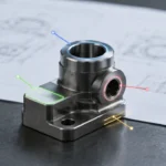
A small CNC-machined metal bracket is being reviewed for MIM conversion. The outer shape, weight-reduction pockets, and several non-critical recesses appear suitable for MIM. However, the part also includes an internal thread, a precision bore, a sealing land, and a datum face used during inspection.
If the team only reviews the overall geometry, the part may look like a straightforward MIM conversion. A better route may be MIM for the main body, tapping for the thread, reaming for the precision bore, controlled machining for the sealing land, and datum review before final inspection planning.
How XTMIM Reviews Machined Features in a CNC-to-MIM Conversion Project
For a CNC-to-MIM conversion project, XTMIM reviews the part from a drawing and process route perspective before tooling decisions are made. The goal is not to force every CNC feature into MIM. The goal is to decide which features can be molded, which features may be sized, and which features should remain machined or specially inspected.
A practical review usually includes overall geometry and wall thickness review, identification of critical dimensions, review of threads, bores, datum faces, sealing surfaces, fit features, material and feedstock availability check, moldability review, sintering distortion review, and secondary operation review for machining, sizing, heat treatment, surface finishing, or inspection.
The review output should be clear enough for quotation and tooling planning: which features are expected to be molded, which features may need sizing, which features should remain machined, and which drawing notes still need clarification from the customer.
What XTMIM Needs
- 2D drawing with critical dimensions and datums
- 3D model for moldability and tooling review
- Marked features that control fit, sealing, motion, or inspection
- Material, volume, and expected secondary operations
What the Review Should Decide
- As-molded features that do not need extra control
- Selected features that may be corrected by sizing
- Functional surfaces that should remain machined
- Questions that must be confirmed before tooling

Core conclusion: Feature-level inspection confirms whether molded, sized, or machined areas meet the drawing function.
Submit Your CNC Drawing for Feature-Level MIM Review
If your CNC part includes threads, precision holes, datum faces, sealing surfaces, bearing seats, or sliding contact areas, XTMIM can review which features may be molded, sized, machined, or confirmed before MIM tooling.
For a faster review, provide the 2D drawing, 3D model, material, annual volume, critical dimensions, and any surface or inspection requirements that must remain controlled after conversion.
FAQ: CNC Features After MIM Conversion
```Which CNC features are most likely to stay machined after MIM?
CNC features after MIM are most likely to stay machined when they control threads, precision bores, datum faces, sealing lands, bearing seats, sliding contact, or repeatable inspection.
Do all CNC features need to stay machined after switching to MIM?
No. Many non-critical profiles, recesses, bosses, pockets, and clearance features may be molded directly in MIM. Machining is usually reviewed for features that control fit, sealing, threads, datum location, sliding contact, bearing function, or inspection repeatability.
Can threads be molded directly in MIM parts?
Some thread-like features may be reviewed for molding or forming, but functional threads often require tapping or another controlled secondary operation. The decision depends on thread size, engagement length, load, assembly torque, material, and production requirements.
Should precision holes be molded or reamed after MIM?
Clearance holes may often be molded, but precision bores, shaft holes, bearing seats, and alignment holes usually need closer review. If the hole controls fit, roundness, concentricity, or assembly alignment, reaming, sizing, or machining may be safer.
When is MIM sizing enough instead of CNC machining?
Sizing may be useful when a selected feature needs dimensional correction but does not require a fully machined surface. It is not a universal substitute for CNC machining. Sealing faces, threaded features, bearing seats, and high-function contact surfaces may still need machining or finishing.
What drawing data is needed to decide which features stay machined?
The review should include a 2D drawing, 3D model, critical dimensions, datum structure, surface finish requirements, thread details, sealing or contact surface notes, material requirement, annual volume, and any known inspection or assembly requirements.
Does keeping some CNC machining remove the cost advantage of MIM?
Not necessarily. Many successful conversions use MIM for the complex main geometry and retain machining only on selected functional features. The cost advantage depends on part complexity, volume, tooling cost, number of secondary operations, and how much CNC time is removed from the original process.