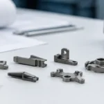
After injection molding, a MIM part is still a green part and must continue through debinding, sintering, and final inspection before it becomes an accepted metal component. After MIM injection molding, the molded part is not a finished metal component. It is a green part: a shaped but fragile part made from fine metal powder …

After MIM injection molding, the molded part is not a finished metal component. It is a green part: a shaped but fragile part made from fine metal powder held together by binder. It may already look like the final component, but it still lacks final density, strength, dimensional stability, and usable metal properties. Before it can become an accepted MIM part, it must pass through controlled handling, debinding, brown part support, sintering shrinkage, possible secondary operations, and final inspection. This matters for design engineers because many MIM risks do not appear at the moment of molding. Thin walls, unsupported features, small holes, cosmetic surfaces, and tight tolerances may survive injection molding but still fail during debinding, sintering, or post-sintering inspection. A practical MIM review must therefore evaluate the whole post-injection route, not only the molded shape.
Engineering Summary
Core answer
Injection molding creates the green part shape, not the final metal condition.
Main process risk
Hidden handling damage, binder removal stress, and sintering shrinkage can appear later.
Best next step
Review thin walls, critical tolerances, visible surfaces, and support strategy before tooling.
Where This Fits in the MIM Process Matrix
This page explains the post-injection path of a MIM part. It does not replace the full process hub or the individual injection, green part handling, debinding, sintering, and inspection pages. Use it when the key question is whether a molded MIM green part is already usable, and what must happen before final acceptance.
| Process Area | What This Page Explains | Where to Read More |
|---|---|---|
| Full MIM route | How the post-injection stages fit into the complete process flow. | Complete MIM process flow |
| Injection molding stage | Why molding creates a green part shape but not final metal properties. | MIM injection molding stage |
| Green part handling | Why ejection, trimming, tray loading, and support can affect later defects. | MIM green part handling |
| Binder removal | Why the green part must be converted into a fragile brown part before sintering. | Binder removal and brown part preparation |
| Sintering and final metal condition | Why shrinkage and densification determine the final metal part condition. | Sintering shrinkage and densification |
| Final inspection | Why the finished part must be checked against drawing, surface, and functional requirements. | MIM inspection process |
Is a MIM Part Finished After Injection Molding?
No. A MIM part is not finished after injection molding. The injection molding step forms the geometry, but it does not create the final metal properties. At this point, the part is still a powder-binder structure. The metal powder is present, but the binder is still holding the shape together.
The real question is not only whether the molded part has the correct appearance. The more important question is whether that shape can survive the next stages without cracking, warping, shrinking unpredictably, or losing critical dimensions.
In plastic injection molding, the molded part may often be close to final use after cooling and trimming. MIM is different. MIM injection molding uses feedstock made from fine metal powder and binder. After molding, the binder must be removed and the metal particles must be sintered together. Only after sintering does the part become a dense metal component suitable for dimensional and functional evaluation.
The Molded Shape Is Not the Final Metal Condition
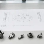
A molded MIM green part has the geometry of the intended part, but it does not have the final internal structure. Its dimensions are also not the same as the final sintered part. The mold cavity is designed with shrinkage compensation because the part will shrink during sintering.
From a design review perspective, this means the drawing cannot be judged only by whether the geometry can be molded. The part must also be reviewed for how it will behave during binder removal, sintering shrinkage, and any post-sintering operations.
Why Binder Still Matters After Molding
Binder is essential during molding because it allows the metal powder to flow into the mold cavity. After molding, however, the binder becomes a temporary support system that must be removed in a controlled way.
If binder removal is too aggressive or poorly supported by part geometry, defects may appear as cracking, blistering, distortion, or internal weakness. These problems are not always visible immediately after molding. Some defects only become clear after debinding or sintering.
Why This Matters for Engineering Review
A part that looks acceptable after molding may still be risky if it has very thin walls, long unsupported features, deep slots, narrow grooves, small holes close to edges, uneven wall thickness, cosmetic surfaces near gate or handling areas, or tight tolerances expected after sintering.
For this reason, engineers should evaluate MIM parts as a full process route, not as a single injection molding operation. For the complete route from feedstock to inspection, see the main metal injection molding process page.
What Is the Green Part After MIM Injection Molding?
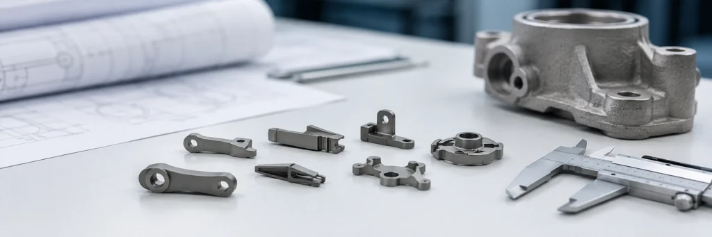
A green part is the molded intermediate part created after MIM injection molding. It contains metal powder and binder in the same general powder-binder structure as the feedstock, but now shaped into the part geometry.
The green part may look solid, but it is not a finished metal part. Its strength mainly comes from the binder system, not from metallurgical bonding between metal particles. This makes MIM green part handling, ejection, trimming, and tray loading important process control points.

Core conclusion: Green part handling is an engineering control point, not a simple transfer operation.
A Green Part Has Shape but Not Final Strength
A common mistake is assuming that the molded green part is strong because it has a defined shape. In practice, green parts can be sensitive to bending, impact, clamping, and local stress. Small damage at this stage can become larger during debinding or sintering.
The risk is higher when the part includes thin ribs, fine pins, long arms, deep slots, thin walls, small bosses, sharp transitions, or delicate cosmetic areas. The part may not fail immediately. Instead, microcracks or stress marks may become visible only after binder removal or sintering shrinkage.
Why Thin Walls and Small Features Are Fragile at This Stage
Thin walls and small features are common reasons why engineers consider MIM. However, these same features can increase green part handling risk. A thin wall may mold successfully but bend during ejection. A small pin may survive molding but crack during tray loading. A delicate edge may be damaged before debinding.
This is why manufacturability review must consider the entire post-injection handling path. A feature is not automatically safe just because it can be filled with feedstock during injection.
How Green Part Damage Can Affect Later Process Steps
Green part damage can create delayed defects. The visible failure may occur after sintering, but the cause may have started during ejection, gate removal, or tray loading.
| Green Part Issue | Possible Later Effect | Why It Matters |
|---|---|---|
| Ejection stress | Crack after debinding or sintering | Binder removal and shrinkage can open hidden stress areas. |
| Poor tray support | Warpage after sintering | Unsupported geometry may move during thermal processing. |
| Gate tearing | Surface defect or local crack | Gate removal can affect cosmetic or functional areas. |
| Contact marks | Visible surface defect after sintering | Handling marks may remain or become more visible. |
| Bent thin feature | Dimensional failure after sintering | Shrinkage may amplify early deformation. |
For a focused explanation of the three intermediate states, see green, brown, and sintered MIM parts.
What Happens Immediately After Demolding?
After demolding, the green part usually goes through several controlled steps before debinding. These steps may look simple, but they have a strong influence on later process stability.
Typical Post-Demolding Actions
- Ejection from the mold cavity
- Separation from runners or gates when required
- Early visual check for obvious molding damage
- Careful transfer to trays or fixtures
- Orientation control before debinding
- Protection from contact damage or bending
Why This Stage Is Often Underestimated
In production, some defects blamed on debinding or sintering actually start during demolding or green part transfer. A molded part may look acceptable but still contain local stress, edge damage, or poor support marks.
Demolding and Ejection Stress
Ejection must remove the green part without creating excessive local stress. If the ejection system pushes against a weak area, the part may deform or crack. If the part has thin walls, deep ribs, or small undercut-like features, ejection risk increases.
For engineers, this means that ejector location, draft, wall balance, and gate area should be reviewed before tooling. A design that can fill well may still be difficult to eject safely.
Gate Removal, Trimming, and Early Visual Checks
Some green parts require gate removal or trimming after molding. This must be done carefully because the part still depends on binder strength. Rough trimming can create cracks, tears, or local surface damage.
Early visual checks usually focus on obvious issues such as short shots, cracks, broken features, contamination, gate damage, or major deformation. This is not the same as final inspection. It is a screening step before the part enters the next process stage.
Tray Loading Before Debinding
Tray loading is more than placing parts into a furnace basket. Part orientation, spacing, support, and contact areas can influence debinding and sintering behavior. Thin or asymmetric parts may need more careful support than compact, balanced parts.
If the part is placed poorly, deformation may start before sintering. For delicate geometries, the support strategy should be considered during engineering review, not after defects appear in production.
Why Does the Part Need Debinding After Injection Molding?
A MIM part needs debinding because the binder used for molding must be removed before the part can become a dense metal component. The green part cannot go directly from molding to final use because it still contains a significant binder phase.
Debinding removes much of this binder while keeping the part shape intact. The remaining structure becomes a brown part, which is porous and fragile but ready for sintering. For deeper stage-level detail, see the MIM debinding process page.
Binder Removal Is Not Optional
Binder is useful during feedstock preparation and injection molding, but it is temporary. If binder remains in the wrong way, the part cannot sinter properly. The goal of debinding is to create a controlled path for binder removal without damaging the shaped part.
This is one reason MIM is different from conventional plastic injection molding. The molded shape is only one stage. The binder must be removed before the metal powder can bond during sintering.
Why Debinding Must Be Controlled
Debinding must be controlled because the green part still needs enough backbone strength while binder is being removed. If binder removal is uneven, too fast, or incompatible with the geometry, the part may develop cracks, swelling, blisters, or internal defects.
The risk depends on binder system, material, wall thickness, part size, section transitions, debinding route, support, orientation, internal holes, and trapped areas. In practice, debinding problems often reflect a combination of feedstock, geometry, and process control rather than a single isolated cause.
How the Green Part Becomes a Brown Part
After debinding, the part is commonly called a brown part. It still has the intended geometry, but much of the binder has been removed. This makes the part more porous and often more fragile than the molded green part.
The brown part is not the final metal component. It is an intermediate structure that must be handled carefully before sintering.
What Is the Brown Part Before Sintering?
The brown part is the debound MIM part before sintering. It has less binder than the green part and contains a porous powder structure. It is closer to the final metal route, but it is still weak and not dimensionally final.
This stage is important because the brown part must survive transfer, loading, and furnace processing. Poor support at this stage can create sintering distortion or cracking.

Core conclusion: MIM part condition changes through process stages; shape alone does not mean final metal properties.
Brown Parts Are Porous and Fragile
A brown part should not be treated like a finished metal component. It may be more sensitive to vibration, handling, or unsupported loading than a green part. Because much of the binder has been removed, the structure depends on powder contact and remaining backbone strength before sintering.
This is why operators and engineers must consider how the part is supported and transferred before sintering.
Why Brown Part Support Matters Before Sintering
Support matters because gravity, contact points, and part geometry can influence how the part moves during thermal processing. Long unsupported areas, thin sections, and asymmetric mass distribution can increase the risk of distortion.
For design engineers, this means part geometry should be reviewed not only for mold filling but also for debinding support and sintering stability.
Common Handling Mistakes Before Sintering
- Treating brown parts like solid metal parts
- Placing delicate parts without enough support
- Allowing parts to contact each other in sensitive areas
- Ignoring thin or long unsupported features
- Assuming all defects after sintering were caused by the furnace
In many cases, the final defect is only the last visible result of an earlier handling or support problem.
What Changes During Sintering?
During sintering, the brown part is heated under controlled conditions so the metal particles bond together. The part shrinks, densifies, and develops usable metal properties. This is the stage where the part changes from a fragile porous structure into a dense metal component.
For deeper stage-level detail, see the MIM sintering process page.

Core conclusion: Shrinkage is planned in MIM, but geometry and support affect final dimensional stability.
Sintering Changes the Part from Porous to Dense
Before sintering, the brown part is not dense enough for final use. During sintering, powder particles bond and the structure becomes more compact. This creates the final metal condition required for strength, density, and functional performance.
The process must be matched to material, geometry, support, and inspection requirements. A small compact part and a thin asymmetric part may behave very differently during sintering.
Why Shrinkage Must Be Expected
Shrinkage is not a defect by itself. It is a normal part of MIM. The mold, tooling compensation, material system, and process route must account for expected shrinkage.
The problem occurs when shrinkage is uneven, poorly predicted, or affected by part geometry. Uneven wall thickness, long unsupported shapes, sharp transitions, or poor support can make final dimensions harder to control.
Why Final Dimensions Depend on More Than the Mold Cavity
The mold cavity is important, but final dimensions also depend on feedstock behavior, green part quality, debinding stability, brown part support, sintering shrinkage, furnace loading, material system, secondary operations, and inspection method.
This is why final tolerance review should happen before tooling. It is not enough to ask whether the part can be molded. The supplier should review whether the part can be molded, debound, sintered, and inspected consistently.
Critical dimensions should also be separated into as-sintered dimensions and post-processed dimensions during drawing review. Some features may be realistic as-sintered, while others may require sizing, machining, finishing, or inspection-specific planning.
Does Every MIM Part Need Secondary Operations After Sintering?
Not every MIM part needs extensive secondary operations after sintering. Some parts are designed to be near-net-shape and may only need cleaning, inspection, or basic finishing. Other parts require additional operations to meet functional, dimensional, cosmetic, or assembly requirements.
Secondary operations do not mean the MIM process failed. In many projects, they are intentionally planned to meet final drawing or application requirements. For more detail, see MIM secondary operations.
When a Sintered MIM Part May Be Close to Final Shape
- The geometry is suitable for MIM shrinkage control.
- Tolerances are realistic for the material and process.
- Functional surfaces are not extremely demanding.
- Surface finish requirements are moderate.
- No critical machining datum is required.
- The part design avoids high-risk distortion features.
When Post-Sintering Operations Are Still Needed
- MIM sizing process for tighter local dimensions
- Sizing or coining
- Threading or precision holes
- Heat treatment
- Surface polishing or tumbling
- Plating, coating, or PVD
- Laser marking
- Assembly or functional testing
What Is Checked Before the Part Is Accepted as a Final MIM Component?
A MIM part should be accepted as a final component only after post-sintering requirements are checked against the drawing and application needs. Visual appearance alone is not enough. For deeper process-level detail, see the MIM inspection process.

Core conclusion: A MIM part becomes a final component only after drawing-based inspection confirms the required dimensions and features.
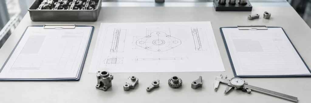
Dimensional Inspection After Shrinkage
Final dimensions should be inspected after sintering and after any required secondary operations. Critical dimensions, datums, holes, slots, wall thickness, and mating features should be reviewed based on drawing requirements.
This is especially important because the part has changed size during sintering. A dimension that looked safe in the molded green part may not remain acceptable after shrinkage.
Surface and Functional Feature Checks
Surface checks may include gate area, handling marks, cracks, deformation, burrs from secondary operations, cosmetic surface condition, and coating or finishing quality when applicable.
Functional features may include assembly fit, hole position, thread condition, contact surface flatness, moving or mating features, wear or locking surfaces, magnetic requirements, or corrosion-related requirements when relevant.
Why Final Inspection Should Be Tied to the Drawing
Final inspection should be drawing-based. The drawing should identify critical dimensions, tolerance requirements, material, surface finish, heat treatment, coating, and functional requirements.
If the drawing does not clearly identify what matters, the supplier may inspect general dimensions but miss the real functional risk. For MIM projects, the best review happens before tooling, when critical requirements can still be adjusted or clarified.
Why This Matters When Engineers Design or Source MIM Parts
Understanding what happens after injection molding helps engineers and buyers avoid unrealistic assumptions. A MIM part is not defined only by its molded shape. It is defined by how the design survives molding, handling, debinding, sintering, secondary operations, and inspection.
Do Not Evaluate MIM Only from the Molded Shape
A design may be moldable but still risky after molding. For example, a thin arm may fill well during injection but distort during sintering. A small hole may be possible in the mold but shift out of tolerance after shrinkage. A cosmetic surface may look acceptable after molding but show gate or handling effects after processing.
Before tooling, the key question is not only whether the part can be molded. It is whether this geometry can remain stable through the complete MIM route.
Review Thin Walls, Unsupported Features, and Critical Dimensions Early
| Review Item | Why It Matters After Injection Molding |
|---|---|
| Thin walls | May deform during handling, debinding, or sintering. |
| Long unsupported features | Higher risk of brown part or sintering distortion. |
| Tight tolerances | Must be reviewed after expected sintering shrinkage. |
| Visible surfaces | May require gate, handling, or finishing review. |
| Small holes or slots | Can be affected by shrinkage and secondary operations. |
| Material requirement | Affects feedstock, debinding behavior, and sintering route. |
| Annual volume | Affects tooling, inspection strategy, and process planning. |
| Surface treatment | May require secondary operations after sintering. |
Share Drawing Requirements Before Tooling
A useful MIM review usually needs 2D drawing, 3D CAD file, material requirement, critical dimensions, tolerance expectations, surface finish requirements, heat treatment or coating requirements, estimated annual volume, application background, and assembly or functional requirements.
If the part has thin walls, small precision features, cosmetic surfaces, tight final dimensions, or previous distortion concerns, you can submit your drawing for MIM process review. If your sourcing team is still preparing project information, use the MIM RFQ preparation guide.
Common Misunderstandings About MIM Parts After Injection Molding
These misunderstandings often appear when MIM is evaluated only as an injection molding process. The table below separates the molded appearance from the real post-injection manufacturing requirements.
| Misunderstanding | Correct Engineering Explanation |
|---|---|
| The molded part is already a metal part. | It is still a green part containing binder and metal powder. |
| If it looks good after molding, it will be good after sintering. | Hidden stress, handling damage, or support problems may appear later. |
| Debinding only cleans the surface. | Debinding removes binder from the internal structure before sintering. |
| Sintering only hardens the part. | Sintering causes densification, shrinkage, and dimensional change. |
| MIM is just plastic injection molding with metal powder. | MIM also requires binder removal, sintering shrinkage control, and final inspection. |
| Secondary operations mean MIM failed. | Many secondary operations are intentionally planned for final tolerance, surface, or function. |
| Final inspection only checks appearance. | Final acceptance should be tied to drawing dimensions, function, surface, and material requirements. |
Composite Field Scenario for Engineering Training: Thin Arm Distortion After Sintering
What problem occurred: A small MIM component with a thin side arm molded successfully. The green parts looked acceptable after injection molding, and early visual checks did not show obvious cracks. However, after sintering, the side arm showed distortion and the final assembly fit was unstable.
Why it happened: The design had a long unsupported feature connected to a thicker main body. During handling and sintering, the thin arm was more sensitive to support conditions and shrinkage behavior than the compact section of the part.
What the real system cause was: The issue was not only a sintering problem. The real system cause was a combination of geometry imbalance, insufficient review of brown part support, and tolerance expectations that did not account for post-sintering movement.
How it was corrected: The design review focused on improving support strategy, adjusting the critical tolerance discussion, and reviewing whether local secondary operations were needed for the assembly feature.
How to prevent recurrence: Before tooling, engineers should identify long unsupported areas, thin arms, and tight functional dimensions. These features should be reviewed for molding, debinding, sintering support, and final inspection as one connected process.
Composite Field Scenario for Engineering Training: Cosmetic Surface Mark Near Gate Area
What problem occurred: A small visible MIM part passed basic molding checks, but the final sintered component showed a cosmetic mark near the gate area. The mark was not acceptable for the visible surface requirement.
Why it happened: The gate area had been selected mainly for filling convenience. The cosmetic requirement of the surface was not clearly emphasized during early review.
What the real system cause was: The root cause was not only gate removal. It was a communication gap between part function, cosmetic surface priority, gate location, and post-sintering finishing expectations.
How it was corrected: The engineering review clarified the visible surface, gate area, finishing expectation, and inspection standard before the next tooling adjustment.
How to prevent recurrence: For visible MIM components, engineers should mark cosmetic surfaces on the drawing and communicate acceptable gate marks, surface finish, and post-sintering finishing requirements before tooling.
When Should You Ask for a MIM Process Review?
You should ask for a MIM process review when the part has features that may behave differently after injection molding than they do in the molded green state. Good review candidates include thin-wall parts, small precision components, long unsupported features, tight post-sintering tolerances, cosmetic surfaces, planned secondary operations, material-specific requirements, or previous cracking, warpage, or dimensional problems.
A practical review should not only ask whether the part can be molded. It should ask whether the part can pass through molding, green part handling, debinding, sintering, post-sintering operations, and inspection with acceptable risk. Please provide drawings, 3D files, material requirements, key tolerances, surface requirements, annual volume, and application background where available.
What XTMIM Will Review
- Process suitability: whether the geometry can move through molding, debinding, sintering, and inspection without excessive risk.
- DFM and tooling risk: thin walls, gate areas, ejection risk, unsupported features, and expected shrinkage behavior.
- Final acceptance path: whether critical dimensions should be as-sintered, sized, machined, finished, coated, or inspected with special controls.
FAQ: What Happens After MIM Injection Molding?
Is a MIM part finished after injection molding?
No. After injection molding, the part is a green part made from metal powder and binder. It still needs debinding, sintering, possible secondary operations, and final inspection before it can be accepted as a finished metal component.
What is a green part in metal injection molding?
A green part is the molded intermediate part produced after MIM injection molding. It has the intended shape, but it still contains binder and does not yet have final metal density, strength, or dimensional stability.
Why does a MIM part need debinding after molding?
Debinding removes much of the binder from the green part before sintering. Without controlled binder removal, the part cannot properly develop the porous structure needed for sintering and may be at risk of cracking, swelling, or internal defects.
What happens during sintering after MIM injection molding?
During sintering, the debound brown part shrinks and densifies as metal particles bond together. This is the stage where the part develops usable metal properties and approaches its final dimensions.
Can MIM parts be used directly after sintering?
Some MIM parts may be close to final shape after sintering, but many require secondary operations such as sizing, machining, polishing, heat treatment, coating, laser marking, or final assembly checks, depending on the drawing and application.
What should engineers review before tooling a MIM part?
Engineers should review thin walls, unsupported features, critical dimensions, gate areas, material requirements, sintering shrinkage risk, surface finish requirements, secondary operations, inspection requirements, and expected annual volume.
When should I submit a MIM drawing for process review?
You should submit a drawing when the part has tight tolerances, thin walls, small features, cosmetic surfaces, sintering distortion risk, material-specific requirements, or planned secondary operations. A process review can identify risks before tooling or production planning.
What information should I send for a MIM process review?
Send 2D drawings, 3D CAD files, material requirements, critical tolerances, surface finish needs, heat treatment or coating requirements, estimated annual volume, and application background. These inputs help the engineering team review molding risk, debinding stability, sintering shrinkage, secondary operation needs, and final inspection requirements.
Engineering Review Note
Reviewed from a MIM Process Planning Perspective
This article was prepared by the XTMIM Engineering Team for product engineers, sourcing teams, and OEM / ODM project reviewers evaluating metal injection molding parts. The review focuses on MIM process suitability, green part handling, debinding risk, sintering shrinkage, tooling risk, secondary operation needs, tolerance expectations, and drawing-based inspection requirements.
Final manufacturability should always be confirmed through project-specific DFM review because MIM performance depends on part geometry, material, feedstock system, tooling strategy, debinding route, sintering support, tolerance requirements, inspection criteria, and production feasibility.
Technical References Note
Technical References for Process Context
This page is a process-explanation resource, not a material specification page. Technical references from MIMA, MPIF, and EPMA are useful because they describe MIM as a process that continues after molding through binder removal, debinding, sintering, shrinkage control, and final inspection or finishing. Material-specific requirements should still be reviewed separately based on alloy, drawing requirements, inspection method, and supplier-specific process capability.
- MIMA Process Overview: MIM — useful for understanding the general MIM process sequence.
- MPIF Metal Injection Molding Overview — useful for understanding green component removal, binder extraction, and sintering.
- EPMA Metal Injection Moulding — useful for understanding MIM shrinkage and process control context.