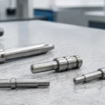
MIM Process Stage Explanation A MIM part does not become a finished metal component immediately after molding. A green part is the molded powder-binder shape. A brown part is the debound structure after much of the binder has been removed. A sintered part is the densified metal component after shrinkage, particle bonding, and final inspection. …

MIM Process Stage Explanation
A MIM part does not become a finished metal component immediately after molding. A green part is the molded powder-binder shape. A brown part is the debound structure after much of the binder has been removed. A sintered part is the densified metal component after shrinkage, particle bonding, and final inspection. For design engineers, these are not just process names. They are different material states with different strength, handling risk, dimensional behavior, and quality-control requirements. This matters when a part has thin walls, small holes, delicate ribs, tight tolerances, or geometry that may distort during debinding or sintering. Before tooling, the practical question is not only whether the shape can be molded, but whether it can pass through green handling, debinding, sintering, and inspection without losing functional dimensions.
To understand where these part states fit into the full metal injection molding process, it helps to separate visible shape from material condition. A molded MIM part may already look like the intended component, but the internal structure is still changing until sintering and final inspection are complete.
Quick Answer: What Is the Difference Between Green, Brown, and Sintered MIM Parts?
Quick answer: Green, brown, and sintered MIM parts are three process states of the same component. A green part is the molded powder-binder shape before debinding. A brown part is the fragile debound structure after much of the binder has been removed. A sintered part is the densified metal component after sintering shrinkage, particle bonding, and final inspection. For engineers, the key difference is handling strength, dimensional stability, distortion risk, and inspection readiness.
These terms do not describe three different products. They describe how the same MIM part changes as it moves through molding, debinding, sintering, and final quality inspection.
| Part Stage | Direct Meaning | Main Engineering Risk |
|---|---|---|
| Green part | A molded MIM part made from fine metal powder and binder before debinding. | Handling damage, cracks, deformation, molding stress, or weak thin features. |
| Brown part | A debound MIM part after much of the binder has been removed. | Fragility, incomplete binder removal, loading damage, or support-related deformation. |
| Sintered part | A densified metal part after high-temperature sintering and controlled shrinkage. | Shrinkage variation, distortion, final dimensional deviation, or unmet inspection requirements. |
The green part has the shape of the component, but it is still a powder-binder body. The brown part has less binder and is more porous, so it often becomes more fragile than it looks. The sintered part is the stage where metal particles bond, density increases, and the component approaches its final size and functional properties.
Terminology note: In MIM, “green” and “brown” describe process states, not strict color specifications. Actual part appearance depends on powder type, binder system, debinding route, and surface condition.
For a deeper view of each process step, see MIM injection molding, MIM debinding process, and MIM sintering process.
Where This Fits in the MIM Process Flow
This page explains part condition changes inside the MIM process. It does not replace the full process route, but helps engineers understand what each physical state means before moving deeper into individual process pages.
Injection Molding → Green Part
The molded shape is formed from feedstock, but the part is still supported by binder. Review demolding, gate areas, thin walls, and handling sensitivity.
Debinding → Brown Part
Binder is removed and the part becomes more porous and fragile. Review binder escape paths, cracks, support, and handling before sintering.
Sintering → Densified Metal
The part shrinks, densifies, and develops metal bonding. Review support, shrinkage consistency, distortion risk, and material response.
Inspection → Acceptance
Final acceptance depends on drawing tolerances, critical dimensions, surface condition, density-related needs, and project-specific inspection requirements.
Why These Stages Matter More Than the Molded Shape
A common mistake is to judge a MIM project only by the molded shape. In practice, molding only creates the green part. Final part quality still depends on controlled binder removal, sintering shrinkage, densification, support strategy, and inspection.
Engineering review question: Can the part survive green handling, debinding, sintering shrinkage, and final inspection without cracking, warping, or missing critical dimensions?
This is why MIM is different from plastic injection molding. A molded plastic part may already be close to its final material condition after cooling. A molded MIM part still contains binder and metal powder before it becomes a functional metal component.
For buyers, this means a good-looking molded trial piece does not automatically prove production stability. For engineers, it means wall thickness, holes, ribs, sharp transitions, support surfaces, and tolerance expectations must be reviewed across the full MIM process flow.
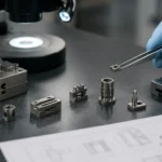
Green Part: What Exists After MIM Injection Molding?

Core conclusion: The part may already show molded geometry, but it is not yet a final metal component.
What a Green MIM Part Contains
A green MIM part is formed when MIM feedstock is injected into a mold. The feedstock contains fine metal powder and a MIM binder system. The binder allows the metal powder to flow during molding and helps the part retain its shape after demolding. At this stage, the component may look similar to the final part, but it is not yet a functional metal component.
The green part is usually larger than the final sintered part because tooling must compensate for expected sintering shrinkage. It may already show holes, bosses, ribs, slots, or small functional features, but the internal structure is still a powder-binder mixture.
Why Green Parts Can Look Finished but Are Not Finished
The green part can mislead new MIM users because the shape is already visible. A buyer may see a molded sample and assume the process is nearly complete. From a manufacturing perspective, that is too early to judge final performance.
The green part does not yet have final metal density, strength, or metallurgical bonding. Its strength comes mainly from the binder-supported structure. Thin sections, sharp transitions, delicate features, and gate-stressed areas may be vulnerable during demolding, trimming, transfer, or tray loading.
Common Green Part Risks Before Debinding
| Green Part Risk | Why It Happens | Why It Matters Later |
|---|---|---|
| Cracking | Low green strength, sharp features, demolding stress, or gate-related stress. | Cracks may open further during debinding or sintering. |
| Deformation | The part is still supported by binder, not by metal bonding. | Distortion may transfer into final geometry. |
| Thin feature damage | Small cross-sections are sensitive during handling. | Breakage risk increases before debinding. |
| Local density inconsistency | Mold filling or packing may not be uniform. | Sintering shrinkage may become less predictable. |
| Surface damage | Green parts can be damaged during transfer or tray handling. | Surface defects may remain or worsen after sintering. |
Green part handling is not a cosmetic issue. Handling method, tray design, gate removal, and transfer control can influence whether the part enters debinding in a stable condition.
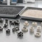
Brown Part: What Changes After Debinding?

Core conclusion: If cracks, contamination, or loading deformation occur at this stage, those problems may remain visible or become worse after sintering.
What Changes During Debinding
During the MIM debinding process, much of the binder is removed from the green part. The part keeps its general shape, but its internal structure changes significantly. Instead of a dense-looking powder-binder body, the brown part becomes a porous powder skeleton with reduced binder support.
The brown part is not yet a fully bonded metal component. Its particles still need sintering to develop final density and strength. Depending on the binder system, material, remaining backbone support, geometry, and handling method, brown part strength can vary from project to project.
Why Brown Parts Are Fragile
A brown part may look stable, but it usually has lower handling robustness than the molded green part. Part of the binder support has been removed, while metallurgical bonding has not yet developed. The internal porosity that allows binder escape also makes the part more sensitive before sintering.
From a production perspective, brown parts must be handled carefully during unloading, tray placement, inspection, and furnace loading. Delicate ribs, thin walls, long unsupported sections, and small features are especially sensitive.
What Can Go Wrong Before Sintering?
| Brown Part Issue | Possible Cause | Later Effect |
|---|---|---|
| Crack | Weak powder skeleton, handling damage, or geometry stress. | Visible sintered crack or rejected part. |
| Chipping | Fragile edge or thin feature during transfer. | Missing feature or dimensional nonconformity. |
| Incomplete debinding | Binder removal is not uniform or geometry blocks escape paths. | Blistering, pore defects, density variation, or internal defects. |
| Contamination | Poor handling or furnace-loading control. | Surface or material-quality concern. |
| Distortion before loading | Poor support or geometry sensitivity. | Final dimensional deviation after sintering. |
The key point is that brown part quality is not only a debinding issue. It becomes a sintering issue if cracks, voids, contamination, or deformation enter the furnace.
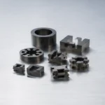
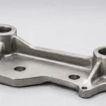
Sintered Part: When Does the MIM Part Become a Real Metal Component?
What Happens During Sintering
The MIM part becomes a functional metal component during the MIM sintering process. At this stage, remaining binder is removed under controlled conditions, metal particles bond together, porosity is reduced, density increases, and the part shrinks toward its final size.
Sintering is where the MIM part develops the density and strength expected from the selected material and process route. However, sintering does not simply finish the part automatically. Geometry, support, material, wall-thickness balance, and furnace conditions all influence the final result.

Core conclusion: Shrinkage is normal in MIM; uneven shrinkage and distortion are the real engineering risks.
Why Shrinkage Is Normal in MIM
Shrinkage is expected in MIM. It is not a defect by itself. Tooling is designed with shrinkage compensation so the molded green part can shrink toward the final dimensional target during sintering.
The real engineering risk is uneven or uncontrolled shrinkage. Thick-to-thin transitions, asymmetric geometry, long unsupported spans, and local mass concentration can make shrinkage behavior less uniform. Tooling compensation supports target dimensions, but final capability still depends on material, geometry, sintering support, inspection method, and project tolerance requirements. For project-level checks, see the MIM tolerance and shrinkage checklist.
What Is Checked After Sintering
Final inspection should focus on the part condition after sintering, not only the molded shape. Depending on the project, MIM final inspection may include:
- Final dimensions and critical tolerances.
- Surface condition.
- Cracks, warpage, or distortion.
- Density-related requirements.
- Hardness or mechanical-property requirements when specified.
- Critical holes, slots, threads, or mating features.
- Secondary operations, such as sizing, machining, heat treatment, polishing, coating, or assembly when needed.

Core conclusion: A sintered part may look finished, but acceptance still depends on drawing requirements, functional features, and inspection criteria.
Green vs Brown vs Sintered MIM Parts: Engineering Comparison Table
This table summarizes the practical differences that matter during drawing review, process planning, and supplier communication.
| Factor | Green Part | Brown Part | Sintered Part |
|---|---|---|---|
| Process position | After injection molding. | After debinding. | After sintering. |
| Material state | Metal powder and binder. | Porous powder skeleton with reduced binder. | Densified bonded metal. |
| Strength source | Binder-supported structure. | Weak particle skeleton. | Metallurgical bonding. |
| Size condition | Oversized molded shape. | Still oversized and porous. | Shrunk toward final target size. |
| Density | Not final. | Not final. | Final or near-final project target. |
| Handling risk | Medium to high. | High. | Lower, but still geometry-dependent. |
| Main risk | Cracking, deformation, molding stress. | Fragility, incomplete debinding, loading damage. | Distortion, shrinkage variation, dimensional deviation. |
| Inspection focus | Green integrity and visible defects. | Debinding condition, cracks, support. | Dimensions, density, surface, mechanical requirements. |
| Common misunderstanding | Looks like a finished part. | Looks stable but is fragile. | Looks final but still needs inspection. |
These are not three names for the same finished part. They are three material states. Each state has a different strength source, risk profile, and inspection logic.
For a design engineer, this table explains why a part that looks acceptable after molding may still fail later. For a buyer, it explains why a reliable MIM supplier should discuss debinding, sintering, support, shrinkage, and inspection before quoting production parts.
How Part Design Affects Green, Brown, and Sintered Conditions
Part design affects all three stages. A design that fills well during injection may still be difficult to debind or may distort during sintering. This is why MIM DFM review should not stop at mold filling. For broader geometry guidance, see the MIM design guide.
| Design Feature | Green Part Risk | Brown Part Risk | Sintered Part Risk |
|---|---|---|---|
| Thin wall | Demolding damage or weak green strength. | Handling crack. | Warpage or shrinkage variation. |
| Thick-to-thin transition | Mold filling stress or local density difference. | Uneven binder removal. | Distortion or internal defect. |
| Long unsupported span | Green deformation. | Loading damage. | Sintering sagging. |
| Small hole or slot | Feature damage during molding or handling. | Difficult binder escape path. | Dimensional deviation or local defect. |
| Asymmetric geometry | Local stress during molding. | Uneven support sensitivity. | Distortion after sintering. |
| Heavy local mass | Packing and cooling variation. | Slower binder removal. | Uneven shrinkage or density variation. |
From a design review perspective, the safer question is not only whether a feature can be molded. The better question is whether it can survive molding, debinding, sintering, and final inspection within the required tolerance and application conditions.
Engineering Review Scenario: Thin Feature Damage That Appears After Debinding
Composite field scenario for engineering training.
A small MIM component included a thin rib connected to a heavier base section. The green part looked acceptable after molding, but small cracks appeared after debinding and became more visible after sintering.
What problem occurred
The thin rib cracked during the green-to-brown transition, and the defect became more visible after sintering.
Why it happened
The rib had low section strength and was connected to a thicker local mass. During debinding, the part became more porous and fragile, while the geometry created local stress concentration.
What the real system cause was
The issue was not only a molding problem. It was a combined design, handling, debinding, and support problem. The feature could be molded, but it was not robust enough through the full MIM route.
How it was corrected
The rib transition was reviewed, support strategy was improved, handling was controlled, and the feature was adjusted to reduce stress concentration.
How to prevent recurrence
Thin ribs, long unsupported sections, and sharp transitions should be reviewed before tooling for green strength, brown part fragility, debinding path, sintering support, and final dimensional requirements.
What Buyers and Engineers Often Misunderstand About MIM Part Stages
| Misunderstanding | Correct Engineering View |
|---|---|
| A green part is already a metal part. | It is a molded feedstock shape, not a final metal component. |
| A brown part is strong enough for normal handling. | Brown parts are usually fragile and require controlled handling. |
| Shrinkage means the process is unstable. | Shrinkage is expected; uncontrolled or uneven shrinkage is the real issue. |
| Only molding determines final quality. | Debinding and sintering strongly affect density, dimensions, and defects. |
| A good-looking trial part guarantees production stability. | Batch consistency, support, inspection, and critical dimensions still matter. |
| Final inspection is only a dimensional check. | Inspection may also involve cracks, surface condition, density, hardness, or other project-specific requirements. |
This matters during supplier evaluation. A supplier who only discusses molding may not be giving the full picture. A supplier who reviews green strength, debinding risk, sintering shrinkage, support, and inspection is more likely to identify problems before tooling or production. For more context, read how debinding and sintering affect MIM part quality.
What Should Be Reviewed Before a MIM Part Moves From Drawing to Production?
Before a MIM project moves from drawing to tooling or production planning, the review should connect the drawing to all three part states.
| Review Item | Why It Matters for Green / Brown / Sintered Stages |
|---|---|
| 2D drawing with tolerances | Identifies final inspection and shrinkage-control requirements. |
| 3D CAD file | Helps evaluate thin walls, undercuts, ribs, support, and geometry risk. |
| Material requirement | Affects feedstock selection, debinding behavior, sintering response, and final properties. |
| Critical dimensions | Determines what must be controlled after shrinkage. |
| Surface requirement | May affect secondary operations or post-sintering finishing. |
| Annual volume | Helps evaluate tooling and production suitability. |
| Application environment | Helps decide material, density, corrosion, wear, magnetic, or strength requirements. |
| Current manufacturing process | Helps judge whether MIM is replacing CNC machining, casting, stamping, PM, or another route. |
A drawing review should not only ask whether the shape can be molded. It should also ask whether the part can be debound, sintered, inspected, and produced consistently within the required function. You can submit a drawing for MIM process review or use the MIM RFQ preparation guide to prepare project information before contacting a supplier.
When Should This Topic Lead to a DFM Review?
A DFM review is useful when the part includes thin walls, delicate ribs, small holes, internal slots, long unsupported geometry, thick-to-thin transitions, asymmetric shapes, tight post-sintering tolerances, or critical sealing, sliding, magnetic, strength, or wear requirements.
It is also useful when a part is being converted from CNC machining, casting, stamping, die casting, PM, or metal 3D printing, or when previous cracking, warpage, density, or dimensional-stability issues have occurred.
Before tooling or production planning, send 2D drawings, 3D CAD files, material requirements, tolerances, surface requirements, annual volume, and application background. XTMIM can support MIM engineering review to evaluate whether green handling, debinding, sintering shrinkage, support, inspection, or secondary operations may affect project feasibility.
FAQ About Green, Brown, and Sintered MIM Parts
What is the difference between a green part and a brown part in MIM?
A green part is the molded MIM part before debinding. It still contains metal powder and binder. A brown part is the debound part after much of the binder has been removed. The brown part is more porous and usually more fragile than it appears.
Is a green MIM part already a metal part?
No. A green MIM part has the shape of the component, but it does not yet have final metal density, strength, or metallurgical bonding. It must still pass through debinding and sintering before it becomes a functional metal component.
Why is a brown MIM part fragile?
A brown part is fragile because much of the binder support has been removed, while the metal particles have not yet fully bonded through sintering. The part may keep its shape, but it has limited mechanical robustness before sintering.
When does a MIM part reach final size?
A MIM part reaches its final size after sintering and final inspection. The green and brown parts are usually oversized because the tooling must compensate for expected sintering shrinkage.
Does sintering always cause shrinkage in MIM parts?
Yes. Shrinkage is expected in MIM because the part densifies during sintering. The engineering challenge is not eliminating shrinkage, but controlling shrinkage consistency and avoiding distortion.
Why should engineers care about green, brown, and sintered stages?
Engineers should care because each stage has different risks. Green parts can crack or deform during handling, brown parts can be fragile after debinding, and sintered parts can show shrinkage variation, warpage, or final dimensional deviation.
What should I send for a MIM process review?
Send a 2D drawing, 3D CAD file, material requirement, critical tolerances, surface requirements, expected annual volume, and application background. These details help evaluate moldability, debinding risk, sintering shrinkage, inspection needs, and production feasibility.
Standards and Technical References Note
This page uses technical references only to support the general MIM process-stage explanation. Standards and association references can support general understanding, but final acceptance should follow customer drawings, material data sheets, inspection requirements, formal project specifications, and supplier-specific process capability evaluation.
- MPIF — Metal Injection Molding process overview: useful for understanding the general feedstock, binder extraction, and sintering route.
- MIMA — Process Overview: MIM: useful for understanding how molding, binder removal, and sintering are separated in the MIM process.