MIM Drawing & DFM Questions Drawing Review Triggers Before Choosing MIM or Die Casting Use the drawing to identify material, geometry, tolerance, surface, and post-process triggers before comparing MIM and die casting quotes. Quick answer: Before choosing MIM or die casting, review the drawing for material route, part size, wall thickness, feature density, critical dimensions, …
MIM Drawing & DFM Questions
Drawing Review Triggers Before Choosing MIM or Die Casting
Use the drawing to identify material, geometry, tolerance, surface, and post-process triggers before comparing MIM and die casting quotes.
Quick answer: Before choosing MIM or die casting, review the drawing for material route, part size, wall thickness, feature density, critical dimensions, visible surfaces, secondary machining areas, and inspection requirements. These triggers do not automatically decide the process, but they show which manufacturing risks must be reviewed first. MIM is usually worth reviewing when the drawing shows a small, dense metal component with complex features, stainless steel or low-alloy steel requirements, fine holes, thin ribs, undercuts, or post-sintering dimensional planning. Die casting is usually worth reviewing when the drawing shows a larger aluminum or zinc alloy component, casting-friendly wall sections, open housing geometry, and surfaces that can tolerate casting and secondary finishing assumptions.

Core conclusion: The process choice should begin with drawing review, not with a generic MIM vs die casting assumption.
Quick Answer: What Drawing Features Should You Review First?
A drawing trigger is not a final answer. It is a signal that a specific engineering question must be checked before tooling, quoting, or supplier selection.
Review Input
Material Route
Check whether the drawing assumes stainless steel, low-alloy steel, aluminum, zinc, or an open functional material requirement.
DFM Trigger
Geometry and Size
Review compact feature density, holes, slots, ribs, bosses, undercuts, part size, wall section, and local thickness transitions.
Quote Boundary
Finished-Part Scope
Separate formed geometry from machining, finishing, inspection, and critical-to-function dimensions before comparing quotes.
Move Toward MIM Review
The drawing may deserve MIM review when it combines steel-based material requirements, compact geometry, fine features, high feature density, and finished-part requirements that can justify tooling and sintering review.
Move Toward Die Casting Review
The drawing may deserve die casting review when it shows aluminum or zinc alloy assumptions, larger shell or housing geometry, casting-friendly wall sections, and surfaces that can be managed through casting and machining.
Pause for Engineering Clarification
The drawing needs clarification when material, critical dimensions, machining allowance, finish requirements, or functional surfaces are not clear enough for suppliers to quote the same finished-part condition.
If the project team is still comparing process routes, the safest next step is to mark the drawing and review it together with the broader MIM vs Die Casting process comparison. The parent comparison page explains the overall process boundary, while this article focuses only on drawing-based review triggers.
Material Route Triggers: Stainless Steel, Low-Alloy Steel, Aluminum, and Zinc
Material is one of the earliest drawing review triggers because it often defines the realistic process route. If a drawing calls for stainless steel, low-alloy steel, soft magnetic steel, or another steel-based functional material, the project team should consider whether the part is better reviewed as a MIM candidate. MIM uses prepared metal powder feedstock, injection molding, debinding, and sintering to produce small, complex, high-density metal parts. This makes the process relevant when the material requirement cannot be met by common aluminum or zinc die casting routes.
Die casting is often reviewed when the drawing is based on aluminum, zinc, or magnesium alloy assumptions. These material routes are common for housings, brackets, covers, heat-dissipation structures, and larger thin-wall components. In those cases, the process review should focus on casting flow, wall thickness, parting line, ejection, machining allowance, surface finish, and dimensional stability after casting.
The main mistake is treating material substitution as a simple cost decision. A steel MIM part and an aluminum die casting may both satisfy a dimensional envelope, but they do not carry the same density, strength, wear, corrosion, magnetic, or finishing assumptions. If the material is not final, the RFQ should describe the functional requirement instead of only naming a process. Before tooling, confirm whether the part needs strength, wear resistance, corrosion resistance, magnetic behavior, weight reduction, conductivity, or cosmetic finish.
| Drawing Material Signal | MIM Review Trigger | Die Casting Review Trigger | What to Confirm Before RFQ |
|---|---|---|---|
| Stainless steel or low-alloy steel | Strong candidate for MIM review if the part is small and complex | Usually not the default die casting route | Functional requirement, corrosion or wear need, target material, secondary operations |
| Aluminum alloy | Possible but usually requires careful MIM feasibility review | Common die casting route for larger housings and brackets | Wall thickness, casting flow, machining surfaces, finish expectations |
| Zinc alloy | Usually not a standard MIM decision route | Common die casting route for small to medium components | Cosmetic surface, plating, parting line, tooling assumptions |
| Material not finalized | Review function first | Review function first | Strength, density, weight, corrosion, assembly, cost target |
If the drawing lists only a process name but not the material function, the supplier may quote the wrong route. For early review, state whether the part needs corrosion resistance, wear resistance, magnetic behavior, low weight, conductivity, cosmetic finish, or a specific assembly function.

Core conclusion: Material route should be reviewed as a functional requirement, not only as a cost or process preference.
Part Size, Weight, and Wall Thickness Triggers
Part size and weight can change the process discussion quickly. MIM is usually reviewed for small to medium-sized metal components where complex geometry, dense material, and production volume can justify tooling and sintering control. A compact part with thin ribs, small holes, undercuts, and multiple functional faces may be difficult or costly to machine from solid stock and may not fit a standard die casting route if the required material is steel-based. For a focused follow-up on this decision factor, review part size and weight triggers before choosing MIM or die casting.
Die casting is often reviewed when the part is larger, shell-like, or housing-like, especially when aluminum or zinc alloys are acceptable. Open geometries, larger projected areas, and casting-friendly wall sections can point toward die casting review. However, large size alone is not enough. Thick-to-thin transitions, isolated heavy sections, long thin walls, and local bosses can create filling, shrinkage, porosity, distortion, or machining risks that must be reviewed before quoting.
Wall thickness is especially important because both processes depend on stable material flow and dimensional control, but in different ways. For MIM, the review should consider feedstock flow, debinding, sintering shrinkage, and distortion risk. For die casting, the review should consider metal flow, solidification behavior, parting line, ejection, and machining stock. A drawing that mixes very thin ribs with thick bosses should not be quoted as a simple shape. It should trigger DFM review before supplier comparison.
| Drawing Feature | Why It Matters | Possible MIM Review Question | Possible Die Casting Review Question |
|---|---|---|---|
| Very compact part with many features | Feature density may favor molded net-shape logic | Can sintering shrinkage and tooling compensation control the features? | Is die casting practical for the material and geometry? |
| Large housing or bracket | Projected area and wall section may favor casting logic | Is the part too large or too thin for stable MIM processing? | Can the wall thickness and flow path support casting? |
| Thick-to-thin transitions | Both processes may face distortion or filling risk | Will debinding and sintering create distortion? | Will casting create porosity, sink, or fill issues? |
| Local bosses and ribs | Tooling and dimensional control may change cost | Can the boss or rib survive green part handling and sintering? | Will the boss or rib require local machining or design revision? |
Do not treat size, weight, or wall thickness as an absolute process rule. These items should trigger engineering review, especially when the part also has material, feature, tolerance, or secondary operation requirements. If the drawing does not define wall section transitions clearly, both MIM and die casting quotes may contain hidden assumptions.
Geometry Triggers: Undercuts, Holes, Slots, Bosses, and Fine Features
Geometry is often the clearest reason to review MIM before die casting. MIM can be useful when a compact metal part has fine features, small holes, thin ribs, undercuts, slots, grooves, and multiple functional surfaces. These features may be difficult to machine economically, especially when production volume is high enough to justify tooling. In MIM, the mold, feedstock flow, green part handling, debinding, sintering shrinkage, and final inspection all affect whether the geometry is realistic.
Die casting can also produce complex shapes, especially larger open geometries, housings, covers, brackets, and ribbed structures. The difference is not simply “complex equals MIM.” The key question is what type of complexity the drawing shows. Compact three-dimensional complexity with steel material requirements may trigger MIM review. Large thin-wall shell geometry with aluminum or zinc material assumptions may trigger die casting review.
Before quoting, the project team should mark undercuts, side holes, blind holes, through holes, internal grooves, sharp transitions, very small radii, thin ribs, and thread features. The supplier should confirm which features can be formed directly, which require tooling action, and which should be machined after molding or casting. For broader MIM suitability context, the published guide on parts suitable for MIM can support the review, while this article stays focused on MIM or die casting drawing triggers.
| Drawing Geometry | MIM Review Trigger | Die Casting Review Trigger | What to Confirm |
|---|---|---|---|
| Fine holes or small slots | May suit compact molded metal geometry | May need core pins, machining, or design review | Minimum feature stability, inspection method, machining fallback |
| Undercuts or side features | May be possible but tooling access must be reviewed | May require side action or design change | Tooling access, demolding direction, acceptable marks |
| Thin ribs and compact bosses | Can support MIM review if geometry is stable | Can support die casting if flow and ejection are stable | Rib thickness, boss height, transition radius |
| Threads | Often require secondary operation or careful design review | Often require machining or inserts depending on design | Thread type, tolerance, inspection, production volume |
The key engineering question is not whether the part is “complex.” The question is whether the complexity is compatible with the material route, tooling access, forming direction, shrinkage or casting behavior, and the required finished-part condition.

Core conclusion: Complex geometry is useful only when reviewed together with material, tooling access, size, and secondary operation requirements.
Critical Dimension and Tolerance Triggers
Critical dimensions should be separated from general dimensions before choosing MIM or die casting. A drawing may contain many dimensions, but only some control assembly, sealing, rotation, sliding, alignment, load transfer, or inspection acceptance. If every dimension is treated as equally critical, the quote may become unrealistic. If critical dimensions are not marked, the supplier may quote based on general process capability and miss the true functional risk.
For MIM, tolerance review must consider molded geometry, debinding, sintering shrinkage, tooling compensation, sizing, machining, and inspection method. Critical holes, flatness areas, datum-based positions, and mating surfaces may require secondary operations or special inspection. The drawing should identify which dimensions can follow general tolerance expectations and which dimensions need engineering review. A deeper MIM-only tooling discussion can be handled through MIM design review before tooling.
For die casting, tolerance review should consider casting variation, parting line, local machining, draft, ejection marks, and surface requirements. Many die cast parts use machining on critical faces, holes, or sealing areas. When comparing MIM and die casting quotes, the project team should confirm whether both quotes include the same post-process and inspection scope.
| Drawing Item | Review Question | Process Selection Impact |
|---|---|---|
| Datum structure | Which surfaces control assembly or inspection? | Determines whether formed surfaces are enough or machining is needed |
| Hole position | Is the hole functional, cosmetic, or only clearance? | Affects tooling, secondary machining, and inspection |
| Flatness / sealing face | Does the surface need post-process control? | Can change total cost and quote comparability |
| General tolerance block | Are tight tolerances applied too broadly? | May create unnecessary process risk or cost |
| Inspection method | How will the dimension be verified? | CMM, gauge, visual, or functional inspection may change supplier review |
A common RFQ problem is that one supplier quotes formed geometry while another quotes a finished part with machining and inspection included. Marking critical dimensions early helps prevent an unfair MIM vs die casting quote comparison.

Core conclusion: A fair MIM vs die casting quote comparison requires both suppliers to understand the same critical dimensions and inspection scope.
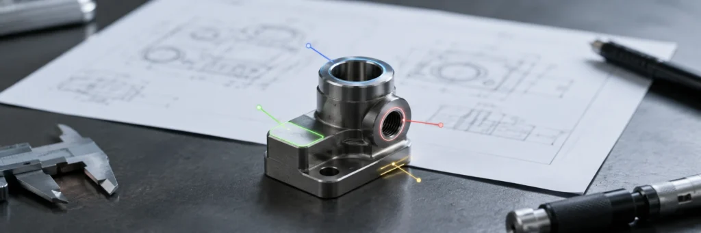
Parting Line, Gate, Ejector, and Surface Requirement Triggers
The drawing should mark visible surfaces, sealing faces, assembly faces, coating areas, and areas where marks are not acceptable. These surfaces often create process selection triggers because both MIM and die casting need tooling decisions that can leave marks or influence dimensional control.
For MIM, gate location, parting line, ejection, green part handling, and sintering support can affect appearance and function. Gate marks or parting line marks may be acceptable on non-functional surfaces but unacceptable on sealing, sliding, or visible cosmetic faces. If a part needs PVD, polishing, plating, passivation, or other finishing, the geometry and material must be reviewed before assuming a finishing route.
For die casting, parting line, ejector marks, overflow, flash control, trimming, and machining surfaces can strongly affect the final part. A housing may be suitable for die casting, but a visible exterior face, sealing face, or precision mounting face may require post-process planning. The drawing should not simply say “smooth surface” or “no marks” without identifying the functional surface and acceptance requirement.
| Drawing Surface Signal | Why It Triggers Review | What to Mark Clearly |
|---|---|---|
| Visible cosmetic face | Gate, parting line, or ejection marks may be unacceptable | Visible side, acceptable mark zones, finish requirement |
| Sealing surface | Flatness and surface condition may affect function | Seal path, flatness need, machining area |
| Coating or finishing area | Process route and material affect finishing result | Coating type, masking area, surface roughness target |
| Assembly face | Dimensional and surface control may be needed | Contact area, datum surface, inspection method |
If a surface is functionally important, mark it before quoting. A surface can be acceptable as-formed, require finishing, require machining, or require a different gate or parting-line discussion. Without this information, the quote may not reflect the final part condition.
Secondary Machining Triggers That Can Change the Quote
Secondary machining can make a MIM quote and a die casting quote look unequal even when the same drawing is used. Threads, reamed holes, flatness areas, bearing seats, sealing faces, precision slots, and tight datum-based features should be identified before the RFQ. Without this information, one supplier may include machining and inspection while another supplier may quote only the molded or cast blank.
For MIM, secondary operations may include sizing, machining, heat treatment, surface finishing, or inspection steps depending on material and geometry. For die casting, machining may be needed for sealing faces, threaded holes, precision bores, flat mounting faces, and tight assembly features. The process comparison should therefore separate formed-part cost from post-process cost.
Before quoting, mark each secondary operation on the drawing and ask suppliers to state whether it is included, optional, or excluded. This helps the project team compare total manufacturing scope instead of only comparing the initial forming method. For MIM-specific quote impact, see how secondary operations affect MIM RFQ cost.
Threads: Are all threaded holes identified with thread type and tolerance?
Precision holes: Are reamed holes, precision bores, or bearing seats marked?
Flatness: Are flatness or sealing surfaces separated from cosmetic surfaces?
Allowance: Are machining allowances shown or discussed?
Inspection: Are post-process inspection requirements included in the quote?
Finish: Are surface finishing requirements included or quoted separately?
For supplier comparison, request a clear breakdown of what is included in the quoted condition: formed blank, machining, finishing, heat treatment, inspection, packaging, and any special fixture or gauge requirement. This is often where the apparent price difference between two process routes changes.
Drawing Review Trigger Matrix for MIM or Die Casting
Use this matrix as a review tool, not as an absolute process decision table. A single trigger rarely decides the manufacturing route. The purpose is to identify which engineering questions should be answered before RFQ, tooling, or supplier comparison.
A drawing review trigger is a feature or requirement that does not decide the manufacturing process by itself, but shows which engineering risk must be checked before comparing MIM and die casting quotes.
| Drawing Item | MIM Review Trigger | Die Casting Review Trigger | What to Confirm |
|---|---|---|---|
| Material | Stainless steel, low-alloy steel, soft magnetic steel, wear-resistant metal route | Aluminum, zinc, or magnesium alloy route | Functional requirement, material flexibility, finish requirement |
| Part size | Compact, dense, feature-rich metal component | Larger housing, bracket, cover, or shell-like structure | Part envelope, projected area, weight, tooling route |
| Wall thickness | Thin ribs or compact sections needing molded metal review | Casting-friendly wall sections with manageable flow | Thick-to-thin transition, local boss or rib risk |
| Geometry | Fine holes, slots, undercuts, small bosses, complex compact shape | Open geometry, larger ribs, housing-style features | Tooling access, demolding or ejection, machining fallback |
| Critical dimensions | Datum-based features, small holes, tight functional areas | Machined faces, bores, sealing areas, cast datum control | Inspection method, post-process need |
| Surface requirement | Gate, parting line, finishing, and sintering support sensitivity | Parting line, ejector, flash, trimming, and surface finish sensitivity | Visible face, sealing face, coating area |
| Secondary operations | Sizing, machining, heat treatment, finishing, inspection | Machining, tapping, trimming, finishing, inspection | Finished-part quote scope |
| Production volume | Tooling can be justified for small complex metal components | Tooling can be justified for larger cast components | Annual volume, project life, tooling budget |
| RFQ readiness | Drawing has enough information for MIM feasibility review | Drawing has enough information for die casting feasibility review | 2D drawing, 3D file, material, critical features, finish |
If Most Triggers Point to MIM Review
Prepare the drawing package for MIM feasibility review, especially material route, feature density, critical dimensions, sintering-related control, and secondary operations.
If Most Triggers Point to Die Casting Review
Prepare the drawing for casting-oriented DFM, including wall sections, flow assumptions, parting line, ejection, trimming, machining stock, and finish expectations.
If Triggers Are Mixed
Do not force an early decision. Ask for an engineering review and require suppliers to state process assumptions, included operations, and excluded scope.
The matrix works best when the team marks the drawing before sending it out. Highlight material assumptions, critical dimensions, functional surfaces, machining areas, and inspection notes. Then ask each supplier to quote the same part condition.
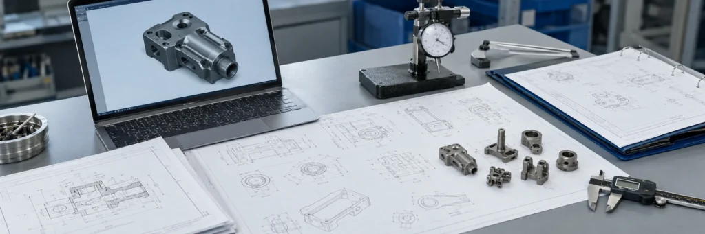
What to Send for an Engineering Review Before Quoting
A useful engineering review package should make the supplier’s assumptions visible. If the drawing package is incomplete, MIM and die casting suppliers may respond with quotes that are not technically comparable. One quote may assume a near-net-shape molded part. Another quote may assume machining after casting. A third quote may exclude surface finishing or inspection.
For an early process recommendation, send the 2D drawing, 3D CAD file, material requirement, annual volume estimate, application function, critical dimensions, surface or finishing expectations, and any assembly constraints. If the material is not fixed, explain the function instead of forcing a process label. If a dimension is critical, mark it. If a surface must be visible, sealed, coated, polished, or machined, mark it.
Minimum Drawing Package
- 2D drawing with tolerance block
- 3D CAD file
- Material requirement or functional material requirement
- Estimated annual volume or project volume range
- Critical dimensions and datum structure
- Surface finishing or coating requirements
- Thread, hole, flatness, and machining notes
- Assembly function and mating part information
- Inspection or testing requirement if known
What to Mark Clearly
- Critical-to-function dimensions
- Non-critical general dimensions
- Sealing surfaces
- Visible cosmetic surfaces
- Threaded holes
- Precision bores or reamed holes
- Flatness zones
- Coating or finishing areas
- Areas where gate, parting line, or ejector marks are not acceptable
Ask Suppliers to State the Quote Condition
A drawing review is more useful when the supplier clearly states what condition is being quoted. Ask whether the quote includes only the molded or cast blank, or whether it also includes machining, finishing, heat treatment, inspection, special packaging, fixtures, and gauge requirements.
This information helps the supplier review manufacturability, tooling direction, shrinkage or casting risk, secondary operation scope, and inspection planning before issuing a quote. For a MIM-specific file checklist, review what to send for a MIM RFQ. For a broader RFQ checklist, use the RFQ Preparation Guide before submitting drawings.

Core conclusion: Better process recommendations come from complete drawings, clear critical dimensions, material requirements, and finishing notes.
Common Mistakes When Comparing MIM and Die Casting from a Drawing
Comparing Quotes Without Matching Assumptions
A MIM quote and a die casting quote are only comparable if both suppliers quote the same finished-part condition. If one quote includes machining, finishing, and inspection while the other only includes the formed blank, the lower number may not represent a lower total cost.
Treating Material Substitution as a Simple Cost Decision
Changing from stainless steel to aluminum or zinc may change strength, weight, corrosion behavior, wear behavior, magnetic response, coating route, and assembly performance. Process selection should not ignore the functional material requirement.
Ignoring Critical Dimensions Until Tooling Discussion
If critical dimensions are not marked early, the supplier may quote based on general process assumptions. After tooling starts, discovering that a hole, flatness area, or sealing face requires machining can change cost, lead time, and inspection scope.
Assuming Complex Geometry Always Means MIM
MIM is strong for compact, complex, high-density metal parts, but not every complex part is a MIM candidate. Large open housings, aluminum or zinc components, and casting-friendly wall structures may point toward die casting review.
Before comparing prices, ask each supplier to clarify material, tooling scope, post-process steps, inspection scope, and packaging assumptions. A quote comparison is only useful when the finished-part condition is the same.
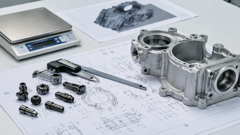
Composite Field Scenario for Engineering Training
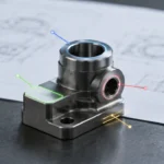
A compact metal component drawing includes a stainless steel material note, two small side holes, one thin rib, a critical datum-based hole position, and one threaded feature. At first glance, the part may look like a machining, casting, or molded metal project. During drawing review, the material route, compact geometry, small feature density, and secondary thread requirement trigger a MIM review before quoting.
The engineering team should not decide the process from one feature alone. The next step is to confirm part size, annual volume, target material, critical dimensions, thread requirement, surface condition, and inspection method. If the part is too large, too thick in local sections, or requires a different material route, the process discussion may change. If the geometry, material, and production assumptions fit, MIM may remain a strong candidate for supplier review.
This scenario is not a customer case. It is a composite field scenario for engineering training, used to explain how drawing triggers should be reviewed before process selection.
FAQ About Drawing Review Before Choosing MIM or Die Casting
Can a drawing alone decide whether MIM or die casting is better?
A drawing can identify strong process triggers, but it usually cannot decide the process alone. The supplier also needs material requirements, annual volume, functional surfaces, critical dimensions, inspection needs, and cost targets before making a reliable recommendation.
What drawing features usually trigger a MIM review?
MIM review is often triggered by small complex metal geometry, stainless steel or low-alloy steel material requirements, fine holes, thin ribs, undercuts, compact feature density, and dimensions that can be reviewed with sintering shrinkage and secondary operation planning.
What drawing features usually trigger a die casting review?
Die casting review is often triggered by aluminum or zinc alloy routes, larger housing or bracket geometry, casting-friendly wall sections, open shapes, ribs, bosses, and surfaces that can be managed through casting, trimming, machining, and finishing.
Should I compare MIM and die casting quotes directly?
Only compare quotes after confirming that both suppliers are quoting the same finished-part condition. Material, tooling, machining, finishing, inspection, and packaging assumptions should be aligned before comparing price.
What files should I send before asking for a process recommendation?
Send the 2D drawing, 3D CAD file, material requirement, estimated annual volume, critical dimensions, surface requirements, secondary operation notes, and any assembly or inspection requirements.
Can secondary machining change the process decision?
Yes. Threads, reamed holes, flatness areas, precision bores, sealing faces, and finishing requirements can change the total cost and may affect whether MIM or die casting is more practical for the project.
Technical References for Process Review
These references are included as general technical background for process review. They should not be read as fixed design limits or as a substitute for part-specific drawing review, material confirmation, DFM feedback, and supplier quotation scope.
- Metal Powder Industries Federation, Metal Injection Molding process overview.
- Zinc Die Casting, Engineering properties and design rules for zinc die casting.
- Die Casting Design, Parting line guidance for die cast components.
Send the Drawing Before Comparing MIM and Die Casting Quotes
Before choosing MIM or die casting, send the drawing package for engineering review. XTMIM can review the material route, critical dimensions, geometry triggers, secondary operations, and RFQ assumptions to help identify whether the part should move toward MIM review, die casting comparison, or further DFM clarification.